Manual - Avaya Paging Solutions
Manual - Avaya Paging Solutions
Manual - Avaya Paging Solutions

You also want an ePaper? Increase the reach of your titles
YUMPU automatically turns print PDFs into web optimized ePapers that Google loves.
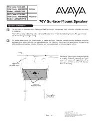
PEC CODE: 5323-108<br />
COM CODE: 408186039<br />
MODEL: LUPCMZONE<br />
Zone <strong>Paging</strong> Module<br />
PCM<br />
ZPM<br />
ZONE A<br />
ZONE B<br />
ZONE C<br />
OFF ON<br />
TALKBACK<br />
BGM<br />
OUT<br />
IN<br />
+<br />
-<br />
+<br />
-<br />
+<br />
-<br />
POWER<br />
IN<br />
RT<br />
RD A<br />
RD B<br />
RD C<br />
LPBGM<br />
VOLUME<br />
ZONE A<br />
ZONE B<br />
ZONE C<br />
GLOBL BGM<br />
LO PWR<br />
HI PWR<br />
RD COM<br />
OUTPUT<br />
LOCAL<br />
BGM<br />
ZONE A<br />
ZONE B<br />
ZONE C<br />
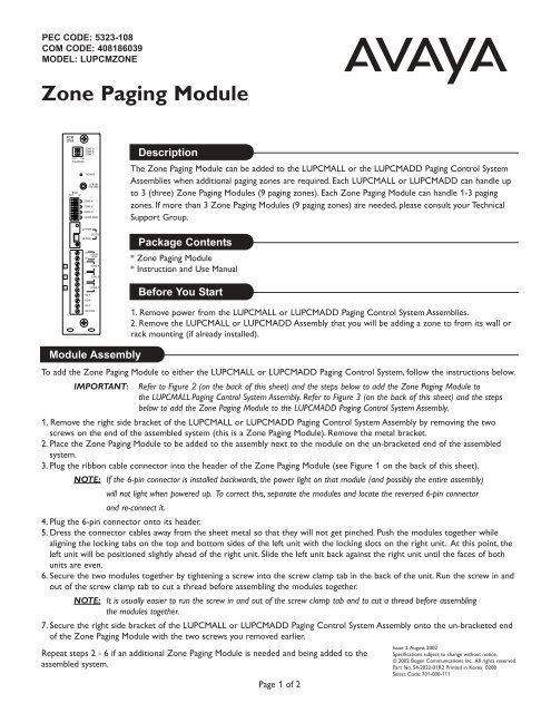
Description<br />
The Zone <strong>Paging</strong> Module can be added to the LUPCMALL or the LUPCMADD <strong>Paging</strong> Control System<br />
Assemblies when additional paging zones are required. Each LUPCMALL or LUPCMADD can handle up<br />
to 3 (three) Zone <strong>Paging</strong> Modules (9 paging zones). Each Zone <strong>Paging</strong> Module can handle 1-3 paging<br />
zones. If more than 3 Zone <strong>Paging</strong> Modules (9 paging zones) are needed, please consult your Technical<br />
Support Group.<br />
Package Contents<br />
* Zone <strong>Paging</strong> Module<br />
* Instruction and Use <strong>Manual</strong><br />
Before You Start<br />
1. Remove power from the LUPCMALL or LUPCMADD <strong>Paging</strong> Control System Assemblies.<br />
2. Remove the LUPCMALL or LUPCMADD Assembly that you will be adding a zone to from its wall or<br />
rack mounting (if already installed).<br />
Module Assembly<br />
To add the Zone <strong>Paging</strong> Module to either the LUPCMALL or LUPCMADD <strong>Paging</strong> Control System, follow the instructions below.<br />
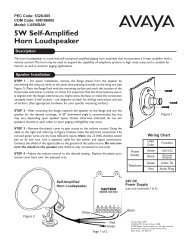
IMPORTANT: Refer to Figure 2 (on the back of this sheet) and the steps below to add the Zone <strong>Paging</strong> Module to<br />
the LUPCMALL <strong>Paging</strong> Control System Assembly. Refer to Figure 3 (on the back of this sheet) and the steps<br />
below to add the Zone <strong>Paging</strong> Module to the LUPCMADD <strong>Paging</strong> Control System Assembly.<br />
1. Remove the right side bracket of the LUPCMALL or LUPCMADD <strong>Paging</strong> Control System Assembly by removing the two<br />
screws on the end of the assembled system (this is a Zone <strong>Paging</strong> Module). Remove the metal bracket.<br />
2. Place the Zone <strong>Paging</strong> Module to be added to the assembly next to the module on the un-bracketed end of the assembled<br />
system.<br />
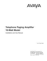
3. Plug the ribbon cable connector into the header of the Zone <strong>Paging</strong> Module (see Figure 1 on the back of this sheet).<br />
NOTE: If the 6-pin connector is installed backwards, the power light on that module (and possibly the entire assembly)<br />
will not light when powered up. To correct this, separate the modules and locate the reversed 6-pin connector<br />
and re-connect it.<br />
4. Plug the 6-pin connector onto its header.<br />
5. Dress the connector cables away from the sheet metal so that they will not get pinched. Push the modules together while<br />
aligning the locking tabs on the top and bottom sides of the left unit with the locking slots on the right unit. At this point, the<br />
left unit will be positioned slightly ahead of the right unit. Slide the left unit back against the right unit until the faces of both<br />
units are even.<br />
6. Secure the two modules together by tightening a screw into the screw clamp tab in the back of the unit. Run the screw in and<br />
out of the screw clamp tab to cut a thread before assembling the modules together.<br />
NOTE: It is usually easier to run the screw in and out of the screw clamp tab and to cut a thread before assembling<br />
the modules together.<br />
7. Secure the right side bracket of the LUPCMALL or LUPCMADD <strong>Paging</strong> Control System Assembly onto the un-bracketed end<br />
of the Zone <strong>Paging</strong> Module with the two screws you removed earlier.<br />
Repeat steps 2 - 6 if an additional Zone <strong>Paging</strong> Module is needed and being added to the<br />
assembled system.<br />
Page 1 of 2<br />
Issue 2,August 2002<br />
Specifications subject to change without notice.<br />
© 2002 Bogen Communications Inc. All rights reserved.<br />
Part No. 54-2022-01R2 Printed in Korea 0208<br />
Select Code: 701-000-111
Figure 1: Connecting to the Assembly<br />
NOTE: For operating instructions,<br />
feature settings, and zone<br />
wiring, please refer to the<br />
LUPCMALL <strong>Paging</strong> Control<br />
System manual.<br />
ALIGN<br />
CONNECTORS<br />
SO LOCKING<br />
RIDGE FACES<br />
HEADER WALL<br />
ALIGN .<br />
POLARIZING<br />
TAB IN SLOT<br />
LOCKING<br />
TAB<br />
LOCKING<br />
SLOT<br />
Figure 2: Adding 2<br />
Zone <strong>Paging</strong> Modules<br />
to a PCMALL <strong>Paging</strong><br />
Control System<br />
ALIGN<br />
CONNECTORS<br />
SO LOCKING<br />
RIDGE FACES<br />
HEADER WALL<br />
ALIGN .<br />
POLARIZING<br />
TAB IN SLOT<br />
SCREW CLAMP<br />
TAB & SLOT<br />
LOCKING<br />
TAB<br />
LOCKING<br />
SLOT<br />
Right Side Bracket<br />
LOCKING<br />
TAB<br />
Rear Side<br />
of Unit<br />
Left Side<br />
LOCKING<br />
SLOT<br />
Figure 3: Adding a<br />
Zone <strong>Paging</strong> Module<br />
to a PCMADD <strong>Paging</strong><br />
Control System<br />
ALIGN<br />
CONNECTORS<br />
SO LOCKING<br />
RIDGE FACES<br />
HEADER WALL<br />
ALIGN .<br />
POLARIZING<br />
TAB IN SLOT<br />
LOCKING<br />
TAB<br />
LOCKING<br />
SLOT<br />
SCREW CLAMP<br />
TAB & SLOT<br />
Page 2 of 2