Manual (144 KB pdf) - Avaya Paging Solutions
Manual (144 KB pdf) - Avaya Paging Solutions
Manual (144 KB pdf) - Avaya Paging Solutions

You also want an ePaper? Increase the reach of your titles
YUMPU automatically turns print PDFs into web optimized ePapers that Google loves.
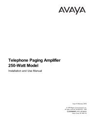
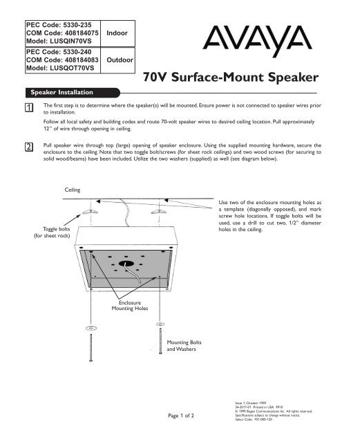
PEC Code: 5330-235COM Code: 408184075Model: LUSQIN70VSPEC Code: 5330-240COM Code: 408184083Model: LUSQOT70VSSpeaker InstallationIndoorOutdoor70V Surface-Mount Speaker1The first step is to determine where the speaker(s) will be mounted. Ensure power is not connected to speaker wires priorto installation.Follow all local safety and building codes and route 70-volt speaker wires to desired ceiling location. Pull approximately12” of wire through opening in ceiling.2Pull speaker wire through top (large) opening of speaker enclosure. Using the supplied mounting hardware, secure theenclosure to the ceiling. Note that two toggle bolt/screws (for sheet rock ceilings) and two wood screws (for securing tosolid wood/beams) have been included. Utilize the two washers (supplied) as well (see diagram below).CeilingToggle bolts(for sheet rock)Use two of the enclosure mounting holes asa template (diagonally opposed), and markscrew hole locations. If toggle bolts will beused, use a drill to cut two, 1/2” diameterholes in the ceiling.EnclosureMounting HolesMounting Boltsand WashersPage 1 of 2Issue 1, October 199954-2017-01 Printed in USA 9910© 1999 Bogen Communications Inc. All rights reserved.Specifications subject to change without notice.Select Code: 701-000-120
3The next step is to attach the speaker wires to theappropriate taps (wires) located on the back of thespeaker.The speaker will also work perfectly wellwith these connections reversed. However, it isimportant to be consistent in the wiring of thespeakers in the system. If adjacent speakers havereversed wiring connections, they will tend to canceleach other’s bass response, diminishing thesound quality.Note: With 70V speakers select the lowest tap setting(1/4W) before testing the speakers.This ensuresthat nobody will be "blasted" when a page is made forthe first time.Based on specific area dB levels, select the desiredpower tap settings:Green = 1/4WYellow = 1/2WOrange = 1WRed = 2WBrown = 4WConnect the power tap wire (use supplied crimptypeconnector) to the (+) side of the pagingsystem.Install the (-) side of the paging system (use suppliedcrimp-type connector) to the black commonlead.Individually tape or clip each tip of exposed wireon the unused power taps and place them neatlyaround the speaker housing. This will ensure thatthere will not be any shorts/grounds or wattageproblems in the speaker enclosure or wire run.Note: Use 22 AWG shielded, twisted pair on allwire runs. Com Code: 401882956. Pec Code:2734-SPK. Connect speaker wire shield to theground (GND) terminal of the amplifier’s output.Carry the ground through all speaker cables bytying the shields of the speaker cables together ina “daisy chain” fashion. Do not connect theshield to the speaker itself. The shield is onlyconnected at the amplifier end and simply floats.Use crimp-typeconnectors(included)Enclosure4Secure the speaker/face plate assembly to themounted enclosure. Use four 1" screws (included).Speaker/FacePlate AssemblyPage 2 of 2