TECHNICAL GUIDE SPECIFICATIONS POWER ... - Online Power, Inc.
TECHNICAL GUIDE SPECIFICATIONS POWER ... - Online Power, Inc.
TECHNICAL GUIDE SPECIFICATIONS POWER ... - Online Power, Inc.

Create successful ePaper yourself
Turn your PDF publications into a flip-book with our unique Google optimized e-Paper software.
<strong>TECHNICAL</strong> <strong>GUIDE</strong> <strong>SPECIFICATIONS</strong><br />
<strong>POWER</strong> WAVE 3<br />
Three Phase, (10 kva to 50 kw)<br />
UL924 Central Lighting Inverter<br />
1 GENERAL<br />
1.1 SCOPE<br />
This guide provides technical information and specifications for OnLine <strong>Power</strong>’s<br />
<strong>Power</strong> Wave 3 central lighting inverter system.<br />
The <strong>Power</strong> Wave 3 is a high reliability, three-phase, solid-state, double conversion, digital<br />
signal processing, high frequency pulse-width modulated (PWM) system that harnesses the<br />
advantages of IGBTs (Insulated-Gate Bipolar Transistor) in its design. The <strong>Power</strong> Wave 3<br />
will provide high quality regulated and conditioned AC power to all types of lighting loads all<br />
of the time because it switches to battery power with virtually zero transfer time upon any<br />
input power loss or disruption.<br />
The <strong>Power</strong> Wave 3 meets UL 924 requirements for emergency lighting system applications<br />
and provides the security of 90 minutes of battery backup power. It is suitable for all lighting<br />
loads including any combination for electronic and security systems, power factor corrected<br />
self-ballast Fluorescent, <strong>Inc</strong>andescent, quartz re-strike, halogen, HID, HPS and LED lighting<br />
during battery backup operation.<br />
The <strong>Power</strong> Wave 3 can be operated at 0 to 100% loading for a minimum of 90 minutes.<br />
Upon the restoration of power from the AC utility line, the system automatically returns to<br />
normal operation without any interruption of power to the load. The <strong>Power</strong> Wave 3 meets UL<br />
924 requirements for recharging the battery while utilizing an industry distinctive small<br />
footprint for its stackable cabinet design. This allows equipment installation in limited<br />
spaces.<br />
1.2 STANDARDS<br />
The <strong>Power</strong> Wave 3 complies with the following standards:<br />
• CSA certified per UL1778,<br />
• UL 924 and CSA 22.2 No. 107.1.<br />
• UL 924/UL 924A – Life Safety for Emergency Back up Lighting<br />
• FCC rules and regulations, Part 15, subpart j, class A<br />
• NEMA PE-1<br />
• NFPA 101 (Life safety code)<br />
• ANSI C62.41 (IEEE 587)<br />
• ANSI C62.42.45 (Cat. A and B)<br />
• TVSS (UL1449 3rd Edition)<br />
6005-033 Rev. B Page 1 of 12
2 PRODUCT DESCRIPTION<br />
APPROVED MANUFACTURERS AND PRODUCT DESCRIPTION<br />
The Inverter shall be an Emergency Central Lighting Inverter and shall be manufactured by:<br />
ON-LINE <strong>POWER</strong>, INC.<br />
5701 Smithway Street, Commerce, CA 90040.<br />
Phone: 1 (800)-227-8899, Fax: 1 (800) 889-6336<br />
<strong>Power</strong> Service – 1 (800) 797-7782<br />
2.1 OPERATION<br />
The system shall utilize high frequency pulse width modulation and digital signal processing<br />
for control and monitoring. The system's automatic overload and short circuit protection of<br />
the inverter in normal and emergency operations shall have 150% momentary surge<br />
capability and withstand a 115% overload for 10 minutes. The system’s protection shall also<br />
include a low battery voltage disconnect to prevent damage to the battery bank. The system<br />
shall supply a clean, computer grade, sinusoidal output waveform with less than 5% total<br />
harmonic distortion at full rated load. Dynamic brownout protection must maintain the<br />
desired voltage without continuously switching to batteries in low voltage situations up to -<br />
15%. The system shall maintain output regulation of less than + 5% under all operating<br />
condition except overload and short circuit. The system shall be able to protect itself from an<br />
internal over-temperature condition and issue an alarm under such conditions.<br />
The <strong>Power</strong> Wave 3 system shall feature:<br />
• An automatic multi-rate, software-controlled charger<br />
• Self-diagnostics<br />
• Programmable system testing capabilities<br />
• A microprocessor controlled diagnostic display panel capable of audible alarms and<br />
visual displays of all warnings<br />
• A DC to AC converter (inverter)<br />
• A battery charger that meets the UL 924 standard<br />
• AC and DC input breakers for protection<br />
• A battery-bank sized for the system's runtime requirements and full rating<br />
• An RS232 communication interface<br />
2.2 SYSTEM DESCRIPTION<br />
2.2.1 INVERTER DESIGN REQUIREMENTS<br />
• Output Load Capacity: The continuous output power rating of the Inverter shall be<br />
[ ] kVA at 0.8 power factor<br />
• Output Voltage: [ ] VAC, 3 phase, 4 wires plus-ground<br />
• Battery Autonomy: The Inverter shall be capable of operating at full load for 90<br />
minutes on battery power, at a temperature of 25 C.<br />
• Battery Type: Valve regulated sealed lead-acid (VRLA) standard, other types are<br />
optional<br />
• Battery Protection: Battery CB, for each string or cabinet for ease of battery<br />
operation and servicing<br />
• Cable Installation: Conduit entries on the top and both sides of enclosure<br />
2.2.2 AC INPUT <strong>SPECIFICATIONS</strong><br />
• Input Voltages: 208Y/120 VAC, 480Y/277 VAC, 4 wires plus ground<br />
6005-033 Rev. B Page 2 of 12
• Frequency: 60 Hz +/- 5%, or 50 Hz +/- 5%<br />
• <strong>Power</strong> Factor: 0.8 PF<br />
• Slew Rate: 1 Hz/second, maximum<br />
• Input Protection: Circuit breaker, contactor<br />
• Input Surge Protection: Optional Transient Voltage Surge Suppressor (TVSS)<br />
• Transfer Time: Zero, no break transfer (unit static transfer must not switch upon<br />
input power loss)<br />
• Input <strong>Power</strong> Connections: Hard wired terminal block<br />
• Number of Wires: 4 wires plus ground<br />
• Cable Installation: Conduit entries on the top and both sides of enclosure<br />
2.2.3 AC OUTPUT <strong>SPECIFICATIONS</strong><br />
• Output Ratings: 10 kVA / 8 kW, 15 kVA / 12 kW, 20 kVA / 16 kW, 25 kVA / 20 kW,<br />
30 kVA / 24 kW, 40 kVA / 32 kW, 50 kVA / 40 kW, 50 kW<br />
• Output Voltages: 208Y/120 VAC, 480Y/277 VAC<br />
• Frequency: 60 Hz +/- 0.5 Hz (when on inverter)<br />
• Voltage Regulation: +5% Regulated within CBEMA curve<br />
• Output Waveform: Sine Wave < 5% THD<br />
• Efficiency: Greater than 90%<br />
• Inverter Overload Capability: 125% for 10 minutes, 150% surge for 10 seconds<br />
• Bypass Overload Capability: 150%<br />
• Protection: Fault current limited<br />
• Non-Linear Load Capability: 100%<br />
• Crest Factor: 3:1 typical<br />
• Output <strong>Power</strong> Connections: Hard wired terminal block<br />
• Output Distribution: Unit shall have an option for internal output circuit breaker(s)<br />
or an external load center attached to the unit for customer use, eliminating the need<br />
for external distribution<br />
• Number of Wires: 4 wires plus ground<br />
2.3 COMPONENT DESCRIPTION<br />
2.3.1 INPUT TERMINAL BLOCK: For ease of installation, an input terminal block shall be hard<br />
wired, and located in the Inverter close to knockouts for incoming power cables. The<br />
conduit entries shall be located on the top and both sides of the cabinet.<br />
2.3.2 INPUT CIRCUIT BREAKER: A circuit breaker shall be provided and hard wired at the Inverter<br />
input for protection from the utility line and associated wiring disturbances. An optional,<br />
higher KAIC breaker shall be available, and should be specified when required.<br />
2.3.3 INPUT CONTACTOR: The Inverter shall have a line contactor to isolate the rectifier in case<br />
of a line problem and allow for a smooth transfer/retransfer to and from bypass.<br />
2.3.4 INPUT TRANSFORMER: An input transformer shall be factory installed inside the standard<br />
Inverter cabinet. It shall be located in the lower part of the cabinet, with a barrier<br />
6005-033 Rev. B Page 3 of 12
separating it from the electronics section, to provide isolation between the line and the<br />
rectifier/inverter circuit.<br />
2.3.5 RECTIFIER: A solid state circuit design, converting incoming AC power to regulated DC<br />
bus voltage for the input to the inverter and battery charger.<br />
2.3.6 INVERTER HEAT SINK ASSEMBLY: The inverter shall feature pulse-width modulation (PWM)<br />
design utilizing high frequency (15 kHz) switched IGBTs. It shall use a true double<br />
conversion system, generating rated AC output from the utility power or the batteries when<br />
in back up mode. The unit shall have a heat sink and power IGBT’s assembly for reduced<br />
switching noise and maximum reliability. The assembly shall come as a FRU (Field<br />
Replaceable Unit) and its design and mounting location shall facilitate easy maintenance.<br />
It shall be located on the electronics shelf with direct access when the door is open and<br />
should be replaceable using only a screwdriver within 15 minutes.<br />
2.3.7 CHARGER: A separate battery charger circuit shall be provided. It uses the same IGBT’s<br />
as in the inverter and provides constant voltage and current limiting control. The battery<br />
float voltage is programmable for the applicable kVA and DC bus ratings. Full recharge of<br />
the batteries shall be in accordance with UL 924. The battery charger will be part of the<br />
Heat Sink Assembly FRU to increase the ease and safety of service. The Heat Sink<br />
Assembly FRU will also include the power circuit board, rectifier, inverter, IGBTs and<br />
driver subassemblies.<br />
2.3.8 STATIC BYPASS: 100% rated, Continuous Duty<br />
The bypass serves as an alternate source of power for the critical load when an input line<br />
failure or abnormal condition prevents operation in inverter mode. It consists of a fully<br />
rated, continuous duty static switch for high speed transfers and features two back-to-back<br />
SCRs to allow make before break transfer. The design shall include a manual bypass<br />
switch, protected within the locked cabinet. It shall be accessible only to authorized<br />
personnel, allowing the unit to stay in bypass at all times for safe work on the unit. Manual<br />
transfer to bypass shall not cause unit trip, nor transfer into battery backup mode. The<br />
static switch shall be able to be powered up by an optional separate power source such as<br />
a generator or other power supply for dual input capabilities.<br />
2.3.8.1 Transfer to Bypass: Will initiate automatically under the following conditions:<br />
• Critical DC bus voltage out of limits<br />
• Low Battery<br />
• Over temperature<br />
• Inverter problem<br />
2.3.8.2 All Transfers to Bypass shall be inhibited for the following conditions:<br />
• Bypass voltage out of limits (+/- 10 % of nominal)<br />
• Bypass frequency out of limits (+/- 3 Hz)<br />
3.2.9 CONTROL LOGIC: The entire inverter operation shall be performed by microprocessor<br />
controlled logic. All operations, parameters, diagnostics, test and protection routines are<br />
firmware controlled. The firmware also compensates for component drift and changes in<br />
operating environment to ensure stable and consistent performance. A self-test and<br />
diagnostics subroutine shall assist in troubleshooting the unit. The Control PCB shall be<br />
located on the front door to isolate it from power wiring and switching devices. This<br />
arrangement shall minimize EMI and allow hot board swaps, in the manual bypass mode.<br />
2.3.10 MANUAL MAINTENANCE BYPASS SWITCH: An auto-manual MBS (Maintenance Bypass<br />
Switch) shall be provided in the Inverter cabinet for connecting power to the critical load<br />
through the external maintenance bypass line. It shall be used when the unit needs to be<br />
de-energized for maintenance, without disrupting power to the load. Operating the switch<br />
6005-033 Rev. B Page 4 of 12
must be strictly restricted to authorized personnel who have cabinet access via the key.<br />
The MBS shall be operated in conjunction with the S-1 synchronization switch, ensuring<br />
full synchronization without inrush current during transfer.<br />
2.3.11 OUTPUT TRANSFORMER: An isolation output transformer shall be utilized to provide<br />
specified output voltage and separate the inverter rectifier/inverter section from the load<br />
disturbances and conducted noise.<br />
2.3.12 MANUAL INVERTER TEST SWITCH: The unit shall have a momentary test switch to allow the<br />
user a manual system test without the need to operate any breakers or shutting down the<br />
system. The test switch shall be in compliance with UL924 rules, well marked, accessible<br />
only after opening a locked front cabinet door and further protected from accidental<br />
activation. The <strong>Power</strong> Wave 3 shall resume normal operation after the test switch is<br />
release.<br />
2.3.13 BATTERY SUBSYSTEM: Sealed, maintenance free VRLA (Valve-Regulated Lead–Acid<br />
battery) batteries shall be provided. The batteries shall have an expected life of 10 years.<br />
The batteries shall be contained in a separate battery cabinet with a dedicated circuit<br />
breaker for battery protection, convenient power cut-off, and servicing.<br />
• Battery run time (based on 100% full load) shall be no less than the specified time.<br />
• Runtime shall comply with UL924 providing a minimum of 90 minutes at full load.<br />
• Specified extended runtimes shall be provided only as an option.<br />
2.4 SYSTEM DIAGNOSTICS/ALARM<br />
2.4.1 FRONT PANEL LCD DISPLAY – STANDARD: The backlit LCD shall have a four line by 20<br />
character display for instant indication of the unit’s status, metering, alarms and battery<br />
condition. The display provides easy read-out on two standard and two optional screens,<br />
providing continuous information with scrolling updates.<br />
2.4.2 STATUS DISPLAY<br />
2.4.2.1 System Status<br />
• Standby: System is performing self-diagnostic<br />
• Start up: Inverter is being started<br />
• Normal: All parameter are acceptable<br />
• Problem: Loss of utility power over load<br />
• Failure: System requires service<br />
2.4.2.2 System Rating in KVA<br />
2.4.2.3 Battery Buss Voltage Status<br />
• Battery ok: Battery voltage is within an acceptable range<br />
• Battery bad: Battery voltage is out of range<br />
2.4.2.4 Input Voltage Status<br />
• Input ok: Input voltage and frequency are within the acceptable range<br />
• Input bad: Input voltage and/or frequency is within an acceptable range<br />
2.4.2.5 Battery Charger Status<br />
• Charger on: Battery charger is charging or keeping batteries at float voltage<br />
• Charger off: Battery is being charged<br />
2.4.2.6 System Internal DC Buss<br />
6005-033 Rev. B Page 5 of 12
• DC ok: DC buss is within the acceptable range<br />
• DC bad: DC buss is out of the acceptable range<br />
2.4.2.7 Static Bypass Status<br />
• On inverter: Critical load is being powered and protected by the inverter<br />
• On by pass: Critical load is being powered from utility power<br />
2.4.2.8 Inverter Output Status<br />
• Out ok: Output is within an acceptable range; critical load is being powered by the<br />
inverter<br />
• Out bad: No output is available from the inverter and the critical load is being<br />
powered from utility power<br />
2.4.3 METERING DISPLAY<br />
• Output voltage<br />
• Output power<br />
• Input voltage<br />
• Input current<br />
• DC buss<br />
• Battery voltage<br />
• Battery current (+) Charging (-) Discharging<br />
2.4.4 EVENTS AND DATA LOGGING – GPTIONAL<br />
• UPS Events time and date stamp of up to 50 scrolling events with freeze function<br />
• Aux. Output CB Trip – up to 20 circuit breakers; Trip alarm on 1st priority trip screen<br />
2.4.5 SYSTEM UTILIZATION SCREEN – RPTIONAL<br />
• Minutes on Battery: Accrued time for UPS in battery backup mode<br />
• System Hours: Accrued time for UPS in normal operation<br />
• Battery Event: The number of times the UPS operated in the backup mode<br />
• Temp: The UPS cabinet temperature<br />
2.4.6 ALARM RELAYS – STANDARD: Dry contact signal relays closing for each of the following<br />
alarm conditions: Input Fail, On Bypass, Low Battery and Summary Alarm.<br />
2.4.7 COMMUNICATION PORTS – STANDARD: Three communication ports are available; two<br />
configured for RS232 protocol and one for RS485 data transfer. All parameters displayed<br />
on the front panel shall be available on these ports for remote monitoring.<br />
2.4.8 <strong>POWER</strong> FLOW MIMIC – OPTIONAL: A laminated overlay with embedded color LEDs<br />
combines information on the front panel display with a graphic power flow visualization for<br />
instant load power status recognition.<br />
2.5 OPERATING MODES<br />
2.5.1 STANDBY MODE<br />
After power is applied, the system is placed in STANDBY mode and a self-check ensues.<br />
During this period, the start subroutine checks for the input voltage and proper operation<br />
of the inverter and bypass SCRs. After the routine is completed and check confirmed OK,<br />
the system goes into the NORMAL mode.<br />
6005-033 Rev. B Page 6 of 12
2.5.2 NORMAL MODE<br />
The input contactor K1 receives a closing signal and connects the input power to the DC<br />
supply transformer. The DC rectifier supplies the battery charger, Control Board and the<br />
DC/AC inverter circuits. The battery charger is then activated allowing the batteries to be<br />
continuously charged. The on-line DC/AC inverter converts the DC voltage to a PWM<br />
(Pulse-Width-Modulation) waveform. This waveform is filtered and reconstructed back to<br />
clean AC output power for critical loads regardless of whether the unit is powered by the<br />
utility or battery backup.<br />
2.5.3 RESPONSE TO INPUT <strong>POWER</strong> ABNORMAL CONDITION<br />
If the system controller senses a change in input frequency of more than +3 Hz or an out<br />
of range input voltage, it will consider it an input failure and will immediately open the input<br />
contactor, isolating the UPS from the facility. At the same time, the charger is turned off<br />
and the battery bank becomes a DC supply source to the inverter circuit, maintaining an<br />
uninterrupted AC supply to the protected load without switching static bypass to prevent<br />
any glitches or risking the load. The LCD screen will display an alarm message. When the<br />
facility power returns and is in phase with inverter, the system controller closes the input<br />
contactor and the system returns to NORMAL automatically.<br />
2.6 BATTERY and BATTERY CHARGER <strong>SPECIFICATIONS</strong><br />
• Standard Run Time: 90 minutes at full load<br />
• Extended Run Time: As required<br />
• Battery Type: Sealed, Maintenance free, lead-acid, VRLA (standard); other types<br />
are optional<br />
• Expected Life: 10 years<br />
• Charger Ampacity: Per UL 924<br />
• Float Voltage: 2.25 volts per cell<br />
• Protection: Circuit breaker in each battery cabinet<br />
• Wiring: Factory shall provide battery interconnecting cables. <strong>Power</strong> cables from the<br />
Inverter to the battery cabinet shall be provided by the customer based on local code.<br />
• Nominal DC Link Voltage: kVA/kW dependent.<br />
• Battery Cabinets: Matching battery cabinets, UL 924 listed, NEMA 1, consult<br />
factory for other types. The specific Inverter and battery cabinet shall be a CSA listed<br />
system per UL924, with a minimum of 90 minutes of battery operation under full load<br />
conditions.<br />
2.7 GLOBAL MONITORING SYSTEM (GMS)<br />
All GMS items are optional. The GMS shall allow for flexibility in remote communications,<br />
metering, measurements, data logging, and system status including internet access.<br />
2.7.1 LOCAL ON INVERTER DISPLAY<br />
• Event Log: A monitoring circuit acquires system data and displays up to 50 of the<br />
most recent date and time stamped events on the front panel display. Its key<br />
selectable menu provides access to events, system information, display, and delete<br />
functions.<br />
• Auxiliary Circuit Breaker Trip Monitor with Event Log: In addition to the event log<br />
and system data, this option registers trips of up to 20 auxiliary output circuit breakers<br />
for monitoring of dedicated circuits. Trip signals from the breakers are displayed on a<br />
CB trip screen. Trip modules mount easily on a DIN rail with auxiliary circuit breakers.<br />
2.7.2 LOCAL ON PC - IA RS232 OR RS485 PORT: This option requires a PC (customer<br />
supplied) and LabView monitoring software on a Windows platform. When the <strong>Power</strong><br />
6005-033 Rev. B Page 7 of 12
Wave 3 is connected to the PC using an RS232 cable, the maximum cable length should<br />
be 25 to 150 feet. By using an RS485 cable, the range can be increased to about 1000<br />
feet.<br />
2.7.3 REMOTE DIAL-UP MONITOR 2000: The Monitor 2000 requires a phone line for remote<br />
operation. The device will send data, voice and text messages to as many as 32<br />
destinations such as phone, fax, pager and e-mail via the phone line. The Manager 2000<br />
Windows software installed on a remote PC displays Inverter parameters, events and<br />
stats graphs. The device will be factory installed and tested in the unit.<br />
2.7.4 WEB/SNMP CARD: This option is a web enabled monitoring device for a unit with an<br />
Internet or network connection. The internal IP Internet address can be pre-installed in<br />
firmware to match the customer’s network settings. The SNMP/Web card can monitor the<br />
inverter on the network through a standard web browser.<br />
2.8 ACCESSORIES<br />
2.8.1 EXTERNAL MAINTENANCE BYPASS SWITCH: If specified by the customer, the bypass switch,<br />
enclosed in a box, could be field mounted on the outside of the inverter cabinet or an<br />
adjacent wall. This box includes a rotary switch with make before break contacts to<br />
provide a single control for transferring to and from maintenance bypass with no load<br />
support interruption.<br />
2.8.2 AUDIO ALARM WITH SILENCE SWITCH: Provides an audible warning signal, acknowledge<br />
and reset for Input Fail, On Bypass, Inverter On, Low Battery and Summary Alarm for any<br />
of the foregoing alarm conditions.<br />
2.8.3 REMOTE UNIT STATUS DISPLAY: The Remote Unit Status Display is available in a console<br />
mount style box. It can also be wall mounted and comes with a 10 foot long “DB”<br />
connector signal cable or optional cable that can be up to 1000 feet long. The Remote<br />
Status Panel Display may requires 120 VAC power, comes with 6 ft power cord, Silence,<br />
LED /Horn test switches. It includes following LEDs: Input Fail, On Bypass, Low Battery,<br />
Summary Alarm.<br />
2.8.4 FORM “C” N/O (NORMALLY/OPEN) CONTACTS FOR ALARMS: Terminal strip TB is provided<br />
with the optional alarm relay board for user connection to the individual alarm contacts.<br />
The Remote Contact Board includes isolated Form C contacts for the same signals as on<br />
the Remote Unit Status Panel.<br />
2.8.5 INPUT TRANSIENT VOLTAGE SURGE SUPPRESSOR (TVSS): TVSS is a DIN rail mounted<br />
device, connected to the Inverter input. Its plug-in phase modules are easily replaceable.<br />
The device contains energy absorbing components and has two-stage protection. When a<br />
protection component is damaged by an absorbed transient, the module will display a flag<br />
indicating a need for replacement. At this time the device is still operational, due to<br />
redundant circuits. After the second spike, the device shows an alarm condition indicating<br />
need for replacement. An additional remote indication contact “TS” is available to allow<br />
remote monitoring of the protection status.<br />
2.8.6 External Status Indicator: The N/O dry contacts are compatible with the IBM AS400<br />
standard from a terminal block and allow the customer to monitor the Low Battery, On<br />
Bypass, Summary, and Input Fail alarms.<br />
2.8.7 NORMALLY ON OR NORMALLY OFF OUTPUT AUXILIARY CIRCUIT BREAKERS: These single<br />
pole 20 amp circuit breakers switch and protect the critical load distribution.<br />
2.8.8 High KAIC Norm On/Off Output Circuit Breaker: These single pole 20 amp circuit<br />
breakers feature a higher KAIC rating then our standard circuit breakers. They are of a<br />
molded case design and mount on a standard DIN rail.<br />
6005-033 Rev. B Page 8 of 12
2.8.9 EXTERNAL OUTPUT AUXILIARY CIRCUIT BREAKERS IN PANEL BOARD: Up to 42 single pole 20<br />
amp circuit breakers can be located on an external panel board that can be mounted on a<br />
side wall of the cabinet or on a wall that is adjacent to the cabinet.<br />
2.8.10 10% INPUT CURRENT HARMONIC FILTER<br />
2.8.11 5% INPUT CURRENT HARMONIC FILTER<br />
2.8.12 EMI FILTER: Complies with: EN55022, 1998 Class “B” Radiated Emission EN55022, 1998<br />
Class “B” conducted emission. FCC Part 15 Class “B” radiated emission; FCC Part 15<br />
Class “B” conducted emission.<br />
2.8.13 DUAL INPUT <strong>POWER</strong> SOURCE<br />
• WYE/WYE<br />
• DELTA/WYE<br />
• DELTA/DELTA<br />
2.8.14 OUTPUT TRANSFORMER WITH HARMONIC TOLERANCE (up to K-50)<br />
2.8.15 SEISMIC MOUNTING BRACKETS: Left / Right seismic floor mounting brackets<br />
2.8.16 STACKABLE RACK: Floor space saving solution (1 rack per 2 cabinets)<br />
2.8.17 BATTERY MONITORING SYSTEM: Single jar, string and entire system monitoring on a local,<br />
remote or web enabled PC. Assessment of actual remaining charge and jars deterioration<br />
for maximum battery life and total backup safety.<br />
2.8.18 EMERGENCY CIRCUIT CONVERTER (ECC): Wall mountable plate with manual test switch<br />
2.8.19 EMERGENCY CONTROL MODULE (ECM): Modular to be installed inside (light fixture or wall).<br />
2.9 MECHANICAL DESIGN AND CONSTRUCTION<br />
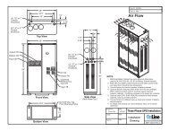
Enclosure: All system components shall be housed in a single floor mounted small footprint<br />
(39”x 18”), freestanding NEMA 1 enclosure. The cabinet should have front access only with<br />
two doors and a depth of no more than 18 inchs, allowing easy component reach from the<br />
front. The enclosure shall have shelves for component separation and clear and accessible<br />
layout. Cabinet doors shall require a key for gaining access. Front access only shall be<br />
required for safety and expedient servicing, adjustments and installation. The cabinets shall<br />
be structurally adequate and have provisions for hoisting, jacking and forklift handling.<br />
Enclosure design shall fully comply with UL 1778 for locked door, unauthorized access<br />
protection and UL 924 for accidental or unauthorized unit shutdown.<br />
2.9.1 CONSTRUCTION: Only quality, unused material shall be used to build the unit under strict<br />
observance of standards and quality workmanship. The cabinets shall be cleaned, primed<br />
and painted matt black. The unit shall be constructed with rigorously tested, burned-in,<br />
replaceable subassemblies. Only two electronic subassemblies: Heat Sink Assembly with<br />
IGBTs and drivers and Control PCBA shall be used for maximum reliability and simple<br />
servicing. All printed circuit assemblies shall have plug connections. Like assemblies and<br />
like components shall be interchangeable.<br />
2.9.2 EARTHQUAKE PROTECTION: The cabinet shall be evaluated for earthquake compliance with<br />
installation of the addition of optional seismic brackets.<br />
2.10 INSTALLATION CONSIDERATIONS<br />
2.10.1 WIRING INSTALLATION: The inverter cabinet conduit entry arrangement shall allow for<br />
flexibility of user wiring installation. The wiring shall be routed thru the top or either side of<br />
the cabinet.<br />
2.10.2 WIRING TERMINATION: The Inverter input and output power connections shall be hard wired<br />
within the cabinet. Optional input line cable and output distribution panel shall be available<br />
6005-033 Rev. B Page 9 of 12
(limited range of units only, please consult factory for details). Input and output terminal<br />
blocks shall be provided for easy field wiring of Inverter and battery cabinets<br />
2.10.3 FACTORY STARTUP: Provides a factory service representative to perform the initial startup<br />
of the Central Lighting Inverter System.<br />
2.10.4 DRAWINGS AND MANUALS: Drawings and manuals supplied with each unit shall include:<br />
• Complete set(s) of shop drawings showing physical dimensions, mounting<br />
information and wiring diagrams.<br />
• Installation Manual(s) with complete instructions for locating, mounting,<br />
interconnection and wiring of the system.<br />
• User Manual(s) outlining complete operating and preventive maintenance<br />
procedures.<br />
2.10.5 INSTALLATION: The Central Lighting Inverter shall be installed in accordance with all<br />
appropriate manufacturers’ installation instructions and in compliance with all appropriate<br />
codes.<br />
2.10.6 ENVIRONMENTAL REQUIREMENTS:<br />
2.10.6.1 Temperature:<br />
• Operating - 0°C to 40°C (32°F to 104°F)<br />
• Storage - 20°C to +45°C (- 4°F to 113°F)<br />
The maximum recommended storage temperature for batteries is 77°F (25°C) for up to<br />
six months. Storage at up to 104°F (40°C) is acceptable for a maximum of three<br />
months.<br />
2.10.6.2 Humidity:<br />
Operating and storage humidity must be maintained within 0 to 95% relative humidity;<br />
non-condensing.<br />
2.10.6.3 Altitude: Up to 6000 feet (1,829 meters)<br />
2.10.6.4 Audible Noise: 57 dB typical on “response curve A”<br />
2.10.6.5 Physical Specifications:<br />
• Cabinet shall be double door, floor mountable, fork liftable, black painted with max<br />
18” depth to maximize front accessibility.<br />
• Cabinet shall be no more than 40 inches wide for best layout (book shelf style)<br />
• Cabinet height shall not exceed 80 inches to allow pass through standard door.<br />
2.11 Maintenance, Service, and Enhanced Warranty Plans:<br />
2.11.1 SERVICE PERSONNEL: The Inverter manufacturer shall employ a nationwide service<br />
organization, with factory-trained Customer Service Engineers dedicated to the start-up,<br />
maintenance, and repair of Inverter and power equipment. The manufacturer shall<br />
provide a fully automated national dispatch center to coordinate field service personnel<br />
schedules. One toll-free number shall reach a qualified support person 24hrs/day,<br />
7days/week and 365 days/year. For emergency service calls, response time from a local<br />
Customer Engineer shall be approximately 15 minutes.<br />
2.11.2 REPLACEMENT PARTS: Parts shall be available through an extensive network to ensure<br />
around- the-clock parts availability throughout the country. Customer Support Parts<br />
6005-033 Rev. B Page 10 of 12
Coordinators shall be on-call 24hrs/day, 7days/week, 365 days a year for immediate parts<br />
dispatch. Parts shall be delivered to the site within 24 hours.<br />
2.11.3 MAINTENANCE TRAINING: In addition to the basic operator training conducted as a part of<br />
the system start-up, classroom courses for customer employees shall be made available<br />
by the manufacturer. The course shall cover Inverter theory, location of subassemblies,<br />
safety, battery considerations and inverter operational procedures. It shall include AC/DC<br />
and DC/AC conversion techniques as well as control and metering, Troubleshooting and<br />
fault isolation using alarm information and internal self-diagnostics interpretation shall be<br />
stressed.<br />
2.12.4 MAINTENANCE CONTRACTS: A comprehensive offering of preventive and full service<br />
maintenance contracts shall be available. An extended warranty and preventive<br />
maintenance package shall be available. All services shall be performed by factory trained<br />
Service Engineers.<br />
2.12.5 SITE TESTING: The manufacturer’s field service personnel shall provide site testing if<br />
requested. The testing shall consist of a complete test of the Inverter system and the<br />
associated accessories supplied by the manufacturer. A partial battery discharge test shall<br />
be provided as part of the standard start-up procedure. The test results shall be<br />
documented, signed, and dated for future reference.<br />
NOTE: This Guide Specification follows Construction Specification Institute guidelines per<br />
CSI MP-2-1,MP-2-2. It is subject to change due to product improvement and/or<br />
enhancement.<br />
Please use this document as a guide specification, and do not hesitate to contact our<br />
application engineering department, should you have any further questions or special<br />
requirements.<br />
You can contact us at: (800) 227-8899 or via e-mail: sales@onlinepower.com<br />
tech@onlinepower.com<br />
WARRANTY<br />
Inverter Module: The Inverter manufacturer shall warrant the Inverter against<br />
defects in materials and workmanship for a period of twenty-four (24) months.<br />
The warranty shall cover all parts and labor for one (1) year period beginning<br />
from the start up, or 18 months from the ship date, whichever comes first.<br />
Optional 1 year extended warranty and maintenance contract packages shall<br />
also be available at the end of the factory maintenance period.<br />
Battery: Battery manufacturer’s standard warranty shall be transferred and<br />
assigned to the end user. It will have a minimum period of ten year.<br />
*kVA/<br />
kW<br />
10/8<br />
15/12<br />
20/16<br />
25/20<br />
Input – Output<br />
Voltage<br />
208Y/120 - 208Y/120<br />
480Y/277 - 480Y/277<br />
480Y/277 - 208Y/120<br />
208Y/120 - 208Y/120<br />
480Y/277 - 480Y/277<br />
480Y/277 - 208Y/120<br />
208Y/120 - 208Y/120<br />
480Y/277 - 480Y/277<br />
480Y/277 - 208Y/120<br />
208Y/120 - 208Y/120<br />
480Y/277 - 480Y/277<br />
480Y/277 - 208Y/120<br />
kVA Model<br />
Number<br />
PW010B05LHT3-VA<br />
PW010H09LHT3-VA<br />
PW010H05LHT3-VA<br />
PW015B05LHT3-VA<br />
PW015H09LHT3-VA<br />
PW015H05LHT3-VA<br />
PW020B05LHT3-VA<br />
PW020H09LHT3-VA<br />
PW020H05LHT3-VA<br />
PW025B05LHT3-VA<br />
PW025H09LHT3-VA<br />
PW025H05LHT3-VA<br />
DC<br />
Volts<br />
BTU/<br />
Hr<br />
192 3032<br />
192 4549<br />
192 6066<br />
288 7582<br />
Total Weights (lbs)<br />
Inverter (Qty)<br />
Cab Battery Cab.<br />
(1 Cabinet)<br />
(1 Cabinets)<br />
1083 lbs<br />
1392 lbs<br />
(1 Cabinet)<br />
1446 lbs<br />
(1 Cabinet)<br />
1679 lbs<br />
(1 Cabinet)<br />
1679 lbs<br />
(2 Cabinets)<br />
2 x1612 lbs<br />
(2 Cabinets)<br />
2 x 1780 lbs<br />
(2 Cabinets)<br />
2 x 2284 lbs<br />
6005-033 Rev. B Page 11 of 12
30/24<br />
40/32<br />
50/40<br />
50kw<br />
208Y/120 - 208Y/120<br />
480Y/277 - 480Y/277<br />
480Y/277 - 208Y/120<br />
208Y/120 - 208Y/120<br />
480Y/277 - 480Y/277<br />
480Y/277 - 208Y/120<br />
208Y/120 - 208Y/120<br />
480Y/277 - 480Y/277<br />
480Y/277 - 208Y/120<br />
208Y/120 - 208Y/120<br />
480Y/277 - 480Y/277<br />
480Y/277 - 208Y/120<br />
PW030B05LHT3-VA<br />
PW030H09LHT3-VA<br />
PW030H05LHT3-VA<br />
PW040B05LHT3-VA<br />
PW040H09LHT3-VA<br />
PW040H05LHT3-VA<br />
PW050B05LHT3-VA<br />
PW050H09LHT3-VA<br />
PW050H05LHT3-VA<br />
PW062B05LHT3-VA<br />
PW062H09LHT3-VA<br />
PW062H05LHT3-VA<br />
288 9098<br />
312 12131<br />
552 15164<br />
552 18000<br />
(1 Cabinet)<br />
1719 lbs<br />
(1 Cabinet)<br />
2066 lbs<br />
(1 Cabinet)<br />
2463 lbs<br />
(1 Cabinet)<br />
2565 lbs<br />
(2 Cabinets)<br />
2 x 2284 lbs<br />
**(3 Cabinets)<br />
3 x 2888 lbs<br />
**(4 Cabinets)<br />
3 x 2284 lbs<br />
1 x 748 lbs<br />
(4 Cabinets)<br />
3 x 2284 lbs<br />
1 x 1948 lbs<br />
***(6 Cabinets)<br />
6 x 2184 lbs<br />
** 3 Cabinets with 10” Hutch OR 3 Cabinets plus One 48” Cabinet.<br />
*** Use 150AH batteries in total of 5 cabinets (5 x 2590 lbs) available.<br />
Weights are approximate weight for basic unit and subject to change without notice. Actual weight can be vary depends<br />
on options.<br />
6005-033 Rev. B Page 12 of 12