when the unit transfers to and from battery ... - Online Power, Inc.
when the unit transfers to and from battery ... - Online Power, Inc.
when the unit transfers to and from battery ... - Online Power, Inc.
- No tags were found...

Create successful ePaper yourself
Turn your PDF publications into a flip-book with our unique Google optimized e-Paper software.
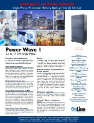
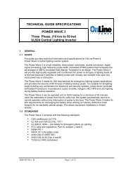
TECHNICAL GUIDE SPECIFICATIONSMini <strong>Power</strong> WaveSingle Phase, (500 <strong>to</strong> 2100 Watts)UL924 Central Lighting Inverter1. SCOPEThe Emergency Lighting <strong>Power</strong> System shall be a solid-state single phase <strong>unit</strong> designed <strong>to</strong>provide regulated <strong>and</strong> conditioned sinusoidal power for emergency lighting applications. TheEmergency Lighting <strong>Power</strong> System shall provide uninterrupted power during all modes ofoperation. There shall be no interruption of power <strong>to</strong> <strong>the</strong> lighting system <strong>when</strong> <strong>the</strong> <strong>unit</strong> <strong>transfers</strong> <strong>to</strong><strong>and</strong> <strong>from</strong> <strong>battery</strong> operation. The Emergency Lighting <strong>Power</strong> System <strong>and</strong> <strong>battery</strong> subsystem shallbe listed <strong>to</strong> UL 924 St<strong>and</strong>ard for Emergency Lighting <strong>and</strong> <strong>Power</strong> Equipment by a nationallyrecognized organization.2. MODES OF OPERATIONNORMAL: During normal operation, utility (or genera<strong>to</strong>r) power is thoroughly conditioned <strong>and</strong>regulated by solid state electronics. The Solid State Electronics in conjunction with <strong>the</strong> input filter,filters noise <strong>and</strong> transients <strong>from</strong> <strong>the</strong> incoming power.Additionally, <strong>the</strong> Solid State Electronics regulates its output voltage <strong>to</strong> within specified limits. Therectifier section maintains <strong>the</strong> batteries in a fully charged state.EMERGENCY: Upon loss of input power or <strong>when</strong> power exceeds <strong>the</strong> specified input limits, <strong>the</strong>control logic shall transfer <strong>to</strong> operation <strong>and</strong> disconnect <strong>the</strong> input line. The transfer <strong>to</strong> <strong>battery</strong> shallbe an uninterrupted or "no break" power transfer. The inverter shall supply power <strong>from</strong> <strong>the</strong>batteries <strong>and</strong> through <strong>the</strong> Solid State Electronics <strong>to</strong> <strong>the</strong> lighting system. The output shall besinusoidal <strong>and</strong> within specified limits. If power is not res<strong>to</strong>red before <strong>the</strong> batteries have beenexhausted, <strong>the</strong> Inverter shall completely shutdown, protecting <strong>the</strong> batteries <strong>from</strong> possibledamage.RECHARGE: Upon res<strong>to</strong>ration of input power <strong>and</strong> before <strong>the</strong> batteries are completely exhausted,<strong>the</strong> Inverter shall au<strong>to</strong>matically return <strong>to</strong> normal operation. This retransfer <strong>to</strong> normal operationshall be uninterrupted. The <strong>battery</strong> charger shall au<strong>to</strong>matically recharge <strong>the</strong> batteries <strong>to</strong> fullcapacity. The <strong>battery</strong> charger shall recharge <strong>the</strong> batteries as set forth in U.L. St<strong>and</strong>ard 9243. MAJOR SYSTEM COMPONENTSEmergency Lighting <strong>Power</strong> System shall consist of <strong>the</strong> following major subsystems:SOLID STATE ELECTRONICS: The Solid State Electronics shall provide regulation <strong>and</strong>conditioning <strong>from</strong> incoming power aberrations. <strong>Power</strong> <strong>to</strong> <strong>the</strong> critical load shall be supplied by <strong>the</strong>Solid State Electronics whe<strong>the</strong>r <strong>the</strong> Inverter is in normal mode or emergency mode. The outputwave shape shall be sinusoidal for all modes of operation.BATTERY SUBSYSTEM: Sealed, maintenance-free batteries shall be provided. The batteriesshall have an expected life of ten (10) years. The batteries shall be fully wired <strong>and</strong> containedwithin its own section. Battery run time (based on 100% full load) shall be no less than ninety(90) minutes. Optional Extended <strong>battery</strong> run times greater <strong>the</strong>n ninety (90) minutes shall beavailable.INVERTER: The Emergency Lighting <strong>Power</strong> System shall convert DC power supplied <strong>from</strong> <strong>the</strong>batteries in<strong>to</strong> AC power.6005-199 Rev A . ECO# 10054 Page 1 of 8
CHARGER: A <strong>battery</strong> charger shall be provided. The <strong>battery</strong> charger shall maintain<strong>the</strong> batteries at full charge. The <strong>battery</strong> charger shall be sized such that it recharges <strong>the</strong>batteries as set forth in UL St<strong>and</strong>ard 924.POWER CONNECTIONS: The Emergency Lighting <strong>Power</strong> System input <strong>and</strong> output shall be hardwired. A main Input, Output <strong>and</strong> DC circuit breaker shall be provided. The main Input circuitbreaker provides over-current protection <strong>and</strong> a means <strong>to</strong> easily disconnect power form <strong>the</strong>lighting system.TRANSFORMER: Unit shall utilize au<strong>to</strong> transformer for 277 Volt input & output only.MONITORING PANEL:• MONITORING PANEL (72VDC UNITS):Front Panel LCD / LED displayThe <strong>unit</strong> shall use LCD display for easy viewing of UPS status.Alarm indica<strong>to</strong>rsThe UPS gives <strong>the</strong> following audible alarms:If UPS is on <strong>battery</strong> <strong>and</strong> <strong>the</strong> ON BATTERY LED is on, UPS will beep every 5seconds.If <strong>the</strong> <strong>battery</strong> capacity is low <strong>and</strong> <strong>the</strong> ON BATTERY LED is flashing, <strong>the</strong> UPS willbeep twice every 5 seconds.If UPS is on bypass <strong>and</strong> <strong>the</strong> BYPASSED LED is on, UPS will no beep.If UPS has an internal fault <strong>and</strong> <strong>the</strong> ALARM LED is on, <strong>the</strong> UPS will give aconstant audible alarm displaying <strong>the</strong> cause on <strong>the</strong> LCD display.The <strong>unit</strong> shall use 5 LED indica<strong>to</strong>r lights:ON/ON-LINE/ON-BAT/BYPASS/FAULT/This green LED is lit <strong>when</strong> UPS has been turned on.When <strong>the</strong> UPS is in normal or static bypass modes, <strong>the</strong>re isvoltage at <strong>the</strong> output terminals <strong>and</strong> this LED will light up in green.While operating in <strong>battery</strong> mode.While operating in bypass mode, this LED will light up in yellow.If any internal error occurs in <strong>the</strong> UPS, this LED will light up in red<strong>and</strong> give off an audible alarm. Press any of <strong>the</strong> but<strong>to</strong>ns on <strong>the</strong>front panel <strong>to</strong> turn off <strong>the</strong> alarm.6005-199 Rev A . ECO# 10054 Page 2 of 8
• MONITORING PANEL (96VDC UNITS):(1) LCD DISPLAY: This Indicates <strong>the</strong> UPS operation information, including UPS status,input/output voltage, input/output frequency, <strong>battery</strong> voltage, <strong>battery</strong> capacity left, output load,inside temperature, <strong>and</strong> <strong>the</strong> times of his<strong>to</strong>ry events. Besides, UPS output voltage <strong>and</strong> outputfrequency can be set <strong>from</strong> <strong>the</strong> LCD panel.(2) KEY SELECT UP:It is pressed <strong>to</strong> select upward <strong>the</strong> UPS status on LCD Display. When thiskey is pressed with <strong>the</strong> LCD Select Down-key simultaneously for 3 seconds, <strong>the</strong> UPS will beswitched off.(3) KEY SELECT DOWN: It is pressed <strong>to</strong> select downward <strong>the</strong> UPS status on LCD Display.(4) KEY ON-OFF CONTROL (only available during maintenance <strong>and</strong> or repari):When this key is pressed with <strong>the</strong> LCD Select Down-Key simultaneously for 3 seconds,<strong>the</strong> UPS will be switched on. Besides, in <strong>the</strong> mode of <strong>battery</strong> back-up, press both of thiskey <strong>and</strong> LCD Select UP-key at <strong>the</strong> same time <strong>to</strong> disable <strong>the</strong> beeps.(5) FAULT LED: This red LED indicates <strong>the</strong> UPS is in fault condition because of inverterabnormal or over-temperature or DC_BUS fault.(6) WARNING LED: This yellow LED indicates <strong>the</strong> UPS is <strong>the</strong> status of overload, bypass or<strong>battery</strong> back-up.(7) NORMAL LED: This green LED indicates <strong>the</strong> UPS is operating normally.6005-199 Rev A . ECO# 10054 Page 3 of 8
4. OPTIONS:• Norm ON C.B options: Unit shall provide up <strong>to</strong> 12 optional 1 pole 20amp din-railoutput circuit breakers.• Norm OFF C.B options: Unit shall provide up <strong>to</strong> 12 optional 1 pole 20amp din-railoutput Circuit Breakers.• Norm OFF or Norm ON W/delay C.B options: Unit shall provide up <strong>to</strong> 12Normally OFF or Normally ON with time delay din-rail Circuit Breakers.• MBS (Internal Maintenance by-pass manual).• Communication interface: Unit shall have RS232 <strong>and</strong> USB communication portOption.• SNMP/Web Card: SNMP shall allow direct moni<strong>to</strong>ring in SNMP based networks formoni<strong>to</strong>ring of <strong>the</strong> Unit through web browser.• Auxiliary TVSS: Input Transient voltage suppressor shall comply with UL1449 thirdedition.• Remote Status Panel: Unit shall be equipped with an optional remote moni<strong>to</strong>ringpanel.• Floor mounting/seismic brackets: Unit shall be floor mountable.• RS232.6005-199 Rev A . ECO# 10054 Page 4 of 8
5. SPECIFICATIONS:• 72VDCSpecifications for 120VVAC /277VACCapacity (W) Description 500 750 1000 1250 1500 2100VoltageSingle Phase 120Vac or 277VacInputVoltage Range120Vac ±10% or or 277VacFrequency60Hz +/- 4HzVoltage (on <strong>battery</strong>)Single Phase 120Vac or 277VacVoltage Range120Vac ±2% or 277VacFrequency (on <strong>battery</strong>) 60 Hz +/-0.5%OutputProtection <strong>and</strong>FilteringTransfer TimeOverload RecoveryHigh Efficiency mode (AC<strong>to</strong> AC)UPS Design TechnologyOutput Wave FormHarmonic dis<strong>to</strong>rtionOverload ProtectionShort Circuit ProtectionVisual Display(LED model)0 msAu<strong>to</strong> transfer <strong>to</strong> UPS> 95 %On-Line / Fully digitized microprocessor controlledSine wave< 3% of T.H.D. at linear load125% for 1 minutes <strong>and</strong> 150% for 10 secondsCircuit breakerUPS on(green), line-mode(green),<strong>battery</strong> mode(yellow), bypass(yellow), fault(red)System/Display/WarningBatteryVisual Display(LCD model)Audible Alarm(Battery back-up)UPS FaultCommunication90 min. UL924 (Sealed,maintenance free lead acid<strong>battery</strong>Input / output voltage, input / output frequency,on-line mode, back up mode, <strong>battery</strong> capacity, loadlevelBeep every 5 secContinuous beeping sound <strong>and</strong> LCD displayRS-232 Serial Port <strong>and</strong> USB6X35 A/H 6X50 A/H 6X50 A/H 6X65 A/H 6X90 A/H 6X100 A/HDimensions (<strong>Inc</strong>hes) Width x Height x Depth 23.5 X 34.25 X 18.25Operating Temperature 0 - 40ºC / 32 ~ 104ºFS<strong>to</strong>rage Temperature -20 ~ 50ºC / -4 ~ 122ºFEnvironmental Audible Noise(1 meter <strong>from</strong> surface)< 40 dBARelative Humidity 0 ~ 95% humidity, non-condensingNote: Due <strong>to</strong> continuous improvement specifications are subject <strong>to</strong> change without prior notice6005-199 Rev A . ECO# 10054 Page 5 of 8
• 96VDCSpecifications for 120VVAC /277VACCapacity (W) Description 500 750 1000 1250 1500 2100VoltageSingle Phase 120Vac or 277VacInputVoltage Range120Vac ±10% or or 277VacFrequency60Hz +/- 4HzVoltage (on <strong>battery</strong>)Single Phase 120Vac or 277VacVoltage Range120Vac ±2% or 277VacFrequency (on <strong>battery</strong>) 60 Hz +/-0.5%OutputProtection <strong>and</strong>FilteringTransfer TimeOverload RecoveryHigh Efficiency mode (AC<strong>to</strong> AC)UPS Design TechnologyOutput Wave FormHarmonic dis<strong>to</strong>rtionOverload ProtectionShort Circuit ProtectionVisual Display(LED model)0 msAu<strong>to</strong> transfer <strong>to</strong> UPS> 95 %On-Line / Fully digitized microprocessor controlledSine wave< 3% of T.H.D. at linear load125% for 1 minutes <strong>and</strong> 150% for 10 secondsCircuit breakerUPS on(green), line-mode(green),<strong>battery</strong> mode(yellow), bypass(yellow), fault(red)System/Display/WarningBatteryVisual Display(LCD model)Audible Alarm(Battery back-up)UPS FaultCommunication90 min. UL924 (Sealed,maintenance free lead acid<strong>battery</strong>Input / output voltage, input / output frequency,on-line mode, back up mode, <strong>battery</strong> capacity, loadlevelBeep every 5 secContinuous beeping sound <strong>and</strong> LCD displayRS-232 Serial Port <strong>and</strong> USB8X26 A/H 8X35 A/H 8X35 A/H 8X50 A/H 8X65 A/H 8X65A/HDimensions (<strong>Inc</strong>hes) Width x Height x Depth 23.5 X 34.25 X 18.25Operating Temperature 0 - 40ºC / 32 ~ 104ºFS<strong>to</strong>rage Temperature -20 ~ 50ºC / -4 ~ 122ºFEnvironmental Audible Noise(1 meter <strong>from</strong> surface)< 40 dBARelative Humidity 0 ~ 95% humidity, non-condensingNote: Due <strong>to</strong> continuous improvement specifications are subject <strong>to</strong> change without prior notice6005-199 Rev A . ECO# 10054 Page 6 of 8
Total/WATTFloor Mount Lighting Inverter90 minute <strong>battery</strong> back up (72 VDC)Model NumbersInput/OutputVoltagesBTU/HrMW.50A0100N1-V 120V/120V 478500W MW.50R0100T1-V 277V/120V 550750W1000W1250W1500WMW.50R2500T1-V 277V/277V 550MW.50A2500T1-V 120V/277V 550MW.75A0100N1-V 120V/120V 492MW.75R0100T1-V 277V/120V 575Cabinet Dimension(W”xH”xD”)23.5x34.25x18.25MW.75R2500T1-V 277V/277V 575MW.75A2500T1-V 120V/277V 575 “MW1.0A0100N1-V 120V/120V 615MW1.0R0100T1-V 277V/120V 675MW1.0R2500T1-V 277V/277V 675MW1.0A2500T1-V 120V/277V 675 “MW1.2A0100N1-V 120V/120V 780MW1.2R0100T1-V 277V/120V 890MW1.2R2500T1-V 277V/277V 890MW1.2A2500T1-V 120V/277V 890 “MW1.5A0100N1-V 120V/120V 925MW1.5R0100T1-V 277V/120V 1100MW1.5R2500T1-V 277V/277V 1100MW1.5A2500T1-V 120V/277V 1100 “MW2.1A0100N1-V 120V/120V 1175MW2.1R0100T1-V 277V/120V 15252100WMW2.1R2500T1-V 277V/277V 1525MW2.1A2500T1-V 120V/277V 1525 “(NOTE)** BTU/HR ARE APROX. NUMBER WITH TOLERANCE ± 15% FORALL MODELS6005-199 Rev A . ECO# 10054 Page 7 of 8
Total/ WATTFloor Mount Lighting Inverter90 minute <strong>battery</strong> back up (96 VDC)Model NumbersInput/OutputVoltagesBTU/HrMW.50A0100N1-S 120V/120V 478500W MW.50R0100T1-S 277V/120V 550750W1000W1250W1500WMW.50R2500T1-S 277V/277V 550MW.50A2500T1-S 120V/277V 550MW.75A0100N1-S 120V/120V 492MW.75R0100T1-S 277V/120V 575Cabinet Dimension(W”xH”xD”)23.5x34.25x18.25MW.75R2500T1-S 277V/277V 575MW.75A2500T1-S 120V/277V 575 “MW1.0A0100N1-S 120V/120V 615MW1.0R0100T1-S 277V/120V 675MW1.0R2500T1-S 277V/277V 675MW1.0A2500T1-S 120V/277V 675 “MW1.2A0100N1-S 120V/120V 780MW1.2R0100T1-S 277V/120V 890MW1.2R2500T1-S 277V/277V 890MW1.2A2500T1-S 120V/277V 890 “MW1.5A0100N1-S 120V/120V 925MW1.5R0100T1-S 277V/120V 1100MW1.5R2500T1-S 277V/277V 1100MW1.5A2500T1-S 120V/277V 1100 “MW2.1A0100N1-S 120V/120V 1175MW2.1R0100T1-S 277V/120V 15252100WMW2.1R2500T1-S 277V/277V 1525MW2.1A2500T1-S 120V/277V 1525 “(NOTE)** BTU/HR ARE APROX. NUMBER WITH TOLERANCE ± 15% FOR ALLMODELS6005-199 Rev A . ECO# 10054 Page 8 of 8