You also want an ePaper? Increase the reach of your titles
YUMPU automatically turns print PDFs into web optimized ePapers that Google loves.
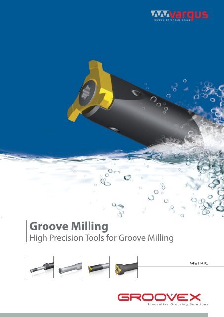
<strong>Groove</strong> <strong>Milling</strong><br />
High Precision Tools for <strong>Groove</strong> <strong>Milling</strong><br />
METRIC
<strong>Groove</strong> <strong>Milling</strong><br />
High Precision Tools for <strong>Groove</strong> <strong>Milling</strong><br />
See it in action<br />
GM Solid<br />
Solid Carbide <strong>Groove</strong> <strong>Milling</strong> tools, for miniature and<br />
small bore diameters<br />
Ø3.0 - 10.00 mm<br />
• Min. bore diameter 6mm<br />
• 4 flutes<br />
• Width of groove 0.7-2.0 mm<br />
• Depth of groove max 1.5mm<br />
Mini-V<br />
Indexable tool with 1 cutting corner for milling<br />
applications with miniature and small bore diameters<br />
Ø8.0 - 16 mm<br />
Available in a variety of grooving profiles:<br />
• Square Grooving<br />
• Round Grooving<br />
• DIN 472/471<br />
GM Slot<br />
<strong>Groove</strong> <strong>Milling</strong> tool with 3 corner indexable inserts, for internal and<br />
external grooving, threading and chamfering applications<br />
• Min. bore diameter 12.7mm<br />
• 3 flutes<br />
• Width of groove 0.74 - 5.25mm<br />
• Depth of groove max 3.25mm<br />
SGM<br />
Shallow <strong>Groove</strong> <strong>Milling</strong>,<br />
for shallow groove milling applications<br />
• Min. bore diameter 48mm<br />
• Long overhang<br />
• Width of groove 1.25-4.0mm<br />
• Depth of groove max 3.5mm<br />
2
GROOVE MILLING CATALOG<br />
GM SOLID<br />
GM Solid Ordering Code System _ _ _ _ _ _ _ _ _ _ _ _ _ _ _ _ _ _ _ _ _ _ _ _ _ _ _ _ _ _ _ _ _ _ _ _ _ _ _ _ _ _ _ _ _ _ _ _ _ _ _ _ _ _ _ _ _ _ _ _ _ _ _ _ _ Page 4<br />
GM Solid - Square Grooving _ _ _ _ _ _ _ _ _ _ _ _ _ _ _ _ _ _ _ _ _ _ _ _ _ _ _ _ _ _ _ _ _ _ _ _ _ _ _ _ _ _ _ _ _ _ _ _ _ _ _ _ _ _ _ _ _ _ _ _ _ _ _ _ _ _ _ _ _ Page 5<br />
GM Solid - Chamfering _ _ _ _ _ _ _ _ _ _ _ _ _ _ _ _ _ _ _ _ _ _ _ _ _ _ _ _ _ _ _ _ _ _ _ _ _ _ _ _ _ _ _ _ _ _ _ _ _ _ _ _ _ _ _ _ _ _ _ _ _ _ _ _ _ _ _ _ _ _ _ _ _ _ Page 5<br />
GM Solid <strong>Groove</strong> <strong>Milling</strong> Technical Data _ _ _ _ _ _ _ _ _ _ _ _ _ _ _ _ _ _ _ _ _ _ _ _ _ _ _ _ _ _ _ _ _ _ _ _ _ _ _ _ _ _ _ _ _ _ _ _ _ _ _ _ _ _ _ _ _ _ Page 6<br />
MINI - V<br />
Mini-V Ordering Code System _ _ _ _ _ _ _ _ _ _ _ _ _ _ _ _ _ _ _ _ _ _ _ _ _ _ _ _ _ _ _ _ _ _ _ _ _ _ _ _ _ _ _ _ _ _ _ _ _ _ _ _ _ _ _ _ _ _ _ _ _ _ _ _ _ _ _ Page 7<br />
Grooving _ _ _ _ _ _ _ _ _ _ _ _ _ _ _ _ _ _ _ _ _ _ _ _ _ _ _ _ _ _ _ _ _ _ _ _ _ _ _ _ _ _ _ _ _ _ _ _ _ _ _ _ _ _ _ _ _ _ _ _ _ _ _ _ _ _ _ _ _ _ _ _ _ _ _ _ _ _ _ _ _ _ _ _ _ _ _ Page 8<br />
Grooving DIN 472 _ _ _ _ _ _ _ _ _ _ _ _ _ _ _ _ _ _ _ _ _ _ _ _ _ _ _ _ _ _ _ _ _ _ _ _ _ _ _ _ _ _ _ _ _ _ _ _ _ _ _ _ _ _ _ _ _ _ _ _ _ _ _ _ _ _ _ _ _ _ _ _ _ _ _ _ _ _ Page 8<br />
Grooving with R _ _ _ _ _ _ _ _ _ _ _ _ _ _ _ _ _ _ _ _ _ _ _ _ _ _ _ _ _ _ _ _ _ _ _ _ _ _ _ _ _ _ _ _ _ _ _ _ _ _ _ _ _ _ _ _ _ _ _ _ _ _ _ _ _ _ _ _ _ _ _ _ _ _ _ _ _ _ _ _ Page 9<br />
Grooving DIN 7993 _ _ _ _ _ _ _ _ _ _ _ _ _ _ _ _ _ _ _ _ _ _ _ _ _ _ _ _ _ _ _ _ _ _ _ _ _ _ _ _ _ _ _ _ _ _ _ _ _ _ _ _ _ _ _ _ _ _ _ _ _ _ _ _ _ _ _ _ _ _ _ _ _ _ _ _ _ Page 9<br />
Toolholder - Carbide Shank with Alloy Steel Head _ _ _ _ _ _ _ _ _ _ _ _ _ _ _ _ _ _ _ _ _ _ _ _ _ _ _ _ _ _ _ _ _ _ _ _ _ _ _ _ _ _ _ _ _ _ _ _ Page 10<br />
Toolholder - Alloy Steel Shank _ _ _ _ _ _ _ _ _ _ _ _ _ _ _ _ _ _ _ _ _ _ _ _ _ _ _ _ _ _ _ _ _ _ _ _ _ _ _ _ _ _ _ _ _ _ _ _ _ _ _ _ _ _ _ _ _ _ _ _ _ _ _ _ _ _ _ Page 10<br />
Mini-V <strong>Groove</strong> <strong>Milling</strong> Technical Data _ _ _ _ _ _ _ _ _ _ _ _ _ _ _ _ _ _ _ _ _ _ _ _ _ _ _ _ _ _ _ _ _ _ _ _ _ _ _ _ _ _ _ _ _ _ _ _ _ _ _ _ _ _ _ _ _ _ _ _ Page 11<br />
GM SLOT<br />
GM Slot Ordering Code System _ _ _ _ _ _ _ _ _ _ _ _ _ _ _ _ _ _ _ _ _ _ _ _ _ _ _ _ _ _ _ _ _ _ _ _ _ _ _ _ _ _ _ _ _ _ _ _ _ _ _ _ _ _ _ _ _ _ _ _ _ _ _ _ _ _ Page 12<br />
GM Slot - Square Grooving _ _ _ _ _ _ _ _ _ _ _ _ _ _ _ _ _ _ _ _ _ _ _ _ _ _ _ _ _ _ _ _ _ _ _ _ _ _ _ _ _ _ _ _ _ _ _ _ _ _ _ _ _ _ _ _ _ _ _ _ _ _ _ _ _ _ _ _ _ _ Page 13<br />
GM Slot - Round Grooving _ _ _ _ _ _ _ _ _ _ _ _ _ _ _ _ _ _ _ _ _ _ _ _ _ _ _ _ _ _ _ _ _ _ _ _ _ _ _ _ _ _ _ _ _ _ _ _ _ _ _ _ _ _ _ _ _ _ _ _ _ _ _ _ _ _ _ _ _ _ Page 14<br />
GM Slot - Chamfering _ _ _ _ _ _ _ _ _ _ _ _ _ _ _ _ _ _ _ _ _ _ _ _ _ _ _ _ _ _ _ _ _ _ _ _ _ _ _ _ _ _ _ _ _ _ _ _ _ _ _ _ _ _ _ _ _ _ _ _ _ _ _ _ _ _ _ _ _ _ _ _ _ _ _ Page 14<br />
GM Slot Holder - Carbide Cylindrical Shank for <strong>Groove</strong> <strong>Milling</strong> Application _ _ _ _ _ _ _ _ _ _ _ _ _ _ _ _ _ _ _ _ _ _ _ _ _ Page 15<br />
GM Slot Holder - Weldon Shank for <strong>Groove</strong> <strong>Milling</strong> Application _ _ _ _ _ _ _ _ _ _ _ _ _ _ _ _ _ _ _ _ _ _ _ _ _ _ _ _ _ _ _ _ _ _ _ _ Page 16<br />
GM Slot <strong>Groove</strong> <strong>Milling</strong> Technical Data _ _ _ _ _ _ _ _ _ _ _ _ _ _ _ _ _ _ _ _ _ _ _ _ _ _ _ _ _ _ _ _ _ _ _ _ _ _ _ _ _ _ _ _ _ _ _ _ _ _ _ _ _ _ _ _ _ _ _ Page 17<br />
SGM<br />
SGM Ordering Code System _ _ _ _ _ _ _ _ _ _ _ _ _ _ _ _ _ _ _ _ _ _ _ _ _ _ _ _ _ _ _ _ _ _ _ _ _ _ _ _ _ _ _ _ _ _ _ _ _ _ _ _ _ _ _ _ _ _ _ _ _ _ _ _ _ _ _ _ _ Page 18<br />
Circlip Non Standard _ _ _ _ _ _ _ _ _ _ _ _ _ _ _ _ _ _ _ _ _ _ _ _ _ _ _ _ _ _ _ _ _ _ _ _ _ _ _ _ _ _ _ _ _ _ _ _ _ _ _ _ _ _ _ _ _ _ _ _ _ _ _ _ _ _ _ _ _ _ _ _ _ _ _ _ Page 19<br />
Circlip DIN 471/472 _ _ _ _ _ _ _ _ _ _ _ _ _ _ _ _ _ _ _ _ _ _ _ _ _ _ _ _ _ _ _ _ _ _ _ _ _ _ _ _ _ _ _ _ _ _ _ _ _ _ _ _ _ _ _ _ _ _ _ _ _ _ _ _ _ _ _ _ _ _ _ _ _ _ _ _ _ Page 20<br />
O Ring DIN 3770 _ _ _ _ _ _ _ _ _ _ _ _ _ _ _ _ _ _ _ _ _ _ _ _ _ _ _ _ _ _ _ _ _ _ _ _ _ _ _ _ _ _ _ _ _ _ _ _ _ _ _ _ _ _ _ _ _ _ _ _ _ _ _ _ _ _ _ _ _ _ _ _ _ _ _ _ _ _ _ _ Page 20<br />
O Ring BS 1806, DIN 3601, DIN 3771 _ _ _ _ _ _ _ _ _ _ _ _ _ _ _ _ _ _ _ _ _ _ _ _ _ _ _ _ _ _ _ _ _ _ _ _ _ _ _ _ _ _ _ _ _ _ _ _ _ _ _ _ _ _ _ _ _ _ _ _ _ Page 21<br />
O Ring BS 4518 _ _ _ _ _ _ _ _ _ _ _ _ _ _ _ _ _ _ _ _ _ _ _ _ _ _ _ _ _ _ _ _ _ _ _ _ _ _ _ _ _ _ _ _ _ _ _ _ _ _ _ _ _ _ _ _ _ _ _ _ _ _ _ _ _ _ _ _ _ _ _ _ _ _ _ _ _ _ _ _ _ Page 21<br />
SGM Toolholders - Multi Insert Holders _ _ _ _ _ _ _ _ _ _ _ _ _ _ _ _ _ _ _ _ _ _ _ _ _ _ _ _ _ _ _ _ _ _ _ _ _ _ _ _ _ _ _ _ _ _ _ _ _ _ _ _ _ _ _ _ _ _ _ Page 22<br />
SGM <strong>Groove</strong> <strong>Milling</strong> Technical Data _ _ _ _ _ _ _ _ _ _ _ _ _ _ _ _ _ _ _ _ _ _ _ _ _ _ _ _ _ _ _ _ _ _ _ _ _ _ _ _ _ _ _ _ _ _ _ _ _ _ _ _ _ _ _ _ _ _ _ _ _ _ Page 23<br />
3
GM Solid<br />
For Miniature and Small Bore Diameters<br />
GM Solid Ordering Code System<br />
Square Grooving<br />
G<br />
1<br />
S<br />
2<br />
4<br />
3<br />
C<br />
4<br />
070<br />
5<br />
6<br />
6<br />
8<br />
7<br />
L15<br />
8<br />
R00<br />
9<br />
VTH<br />
10<br />
1 - Product Line<br />
G - Grooving<br />
7 - <strong>Groove</strong> Depth<br />
08 - 0.8 mm<br />
12 -1.2 mm<br />
15 -1.5 mm<br />
2 - Type<br />
Solid<br />
8 - VV<br />
L15 -15 mm<br />
L25 -25 mm<br />
L35 -35 mm<br />
3 - Number of Flutes<br />
4 - Four flutes<br />
6 - Six flutes<br />
4 - Cooling<br />
C - Cooling<br />
None - Without Cooling<br />
9 - Radius <strong>Groove</strong> Width Length<br />
R00 - None<br />
10 - Carbide Grade Width Length<br />
VTH<br />
5 - <strong>Groove</strong> Width (mm)<br />
070 - 0.7 mm<br />
080 - 0.8 mm<br />
090 - 0.9 mm<br />
100 - 1.0 mm<br />
150 - 1.5 mm<br />
200 - 2.0 mm<br />
6 -Shank Diameter (mm)<br />
06 - 6 mm<br />
08 - 8 mm<br />
10 - 10 mm<br />
Chamfering<br />
G<br />
1<br />
M<br />
2<br />
4<br />
3<br />
CH<br />
4<br />
90<br />
5<br />
060<br />
6<br />
06<br />
7<br />
L15<br />
8<br />
VTH<br />
9<br />
1 - Product Line<br />
G - Grooving<br />
7 - Max. Chamfer Size<br />
06 - 0.6 mm<br />
12 - 1.2 mm<br />
2 - Type<br />
<strong>Milling</strong><br />
3 - Number of Flutes<br />
4 - Four flutes<br />
8 - Tool Cutting Length<br />
L15 - 15 mm<br />
L25 - 25 mm<br />
L35 - 35 mm<br />
4 - Profile<br />
CH - Chamfering<br />
9 - Carbide Grade<br />
VTH<br />
5 - Angle of Chamfering<br />
90<br />
6 - Shank Diameter<br />
030 - 3mm<br />
040 - 4mm<br />
050 - 5mm<br />
060 - 6mm<br />
080 - 8mm<br />
4
GM Solid - Square Grooving<br />
L<br />
D2<br />
D2<br />
L2<br />
L2<br />
L<br />
Dh6<br />
Dh6<br />
GM Solid<br />
w<br />
T<br />
w<br />
T<br />
Width of <strong>Groove</strong> Depth of Cut Ordering Code Dimensions mm<br />
W +/-0.02 mm T max mm D2 Dh6 L L2 No. of Flutes<br />
0.7<br />
0.8<br />
GS4C 0700608-L15R00 VTH<br />
GS4C 0800608-L15R00 VTH<br />
0.9 0.8<br />
GS4C 0900608-L15R00 VTH 5.9 6 58 15 4<br />
1.0 GS4C 1000608-L15R00 VTH<br />
1.5 GS4C 1500608-L15R00 VTH<br />
0.7<br />
GS4C 0700812-L25R00 VTH<br />
0.8 GS4C 0800812-L25R00 VTH<br />
0.9 GS4C 0900812-L25R00 VTH<br />
1.2<br />
1.0 GS4C 1000812-L25R00 VTH<br />
7.9 8 68 25 4<br />
1.5 GS4C 1500812-L25R00 VTH<br />
2.0 GS4C 2000812-L25R00 VTH<br />
0.7<br />
0.8<br />
GS6C 0701015-L35R00 VTH<br />
GS6C 0801015-L35R00 VTH<br />
0.9 GS6C 0901015-L35R00 VTH<br />
1.5<br />
1.0 GS6C 1001015-L35R00 VTH<br />
9.9 10 78 35 6<br />
1.5 GS6C 1501015-L35R00 VTH<br />
2.0 GS6C 2001015-L35R00 VTH<br />
GM Solid - Chamfering<br />
L2<br />
L<br />
L2<br />
D2<br />
Dh6<br />
D2<br />
Dh6<br />
s<br />
90 ◦<br />
T<br />
w T<br />
w<br />
s<br />
90 ◦ L<br />
Depth of Cut Ordering Code Dimensions mm<br />
T max mm D2 S L L2 W No. of Flutes Dh6<br />
0.6 GM3CH90 03006-L12 VTH 2.9 0.7 39 12<br />
3<br />
3<br />
0.8 GM3CH90 04008-L10 VTH 3.9 0.9 51 10 4<br />
1.1 GM4CH90 05011-L12 VTH 4.95 1.2 51 12.5<br />
5<br />
0.6<br />
GM4CH90 06006-L15 VTH<br />
58 15<br />
0.2<br />
5.9 0.8<br />
GM4CH90 06006-L25 VTH 68 25<br />
4<br />
6<br />
1.2<br />
GM4CH90 08012-L25 VTH<br />
68 25<br />
7.9 1.4<br />
GM4CH90 08012-L35 VTH 78 35<br />
8<br />
5
GM Solid <strong>Groove</strong> <strong>Milling</strong> Technical Data<br />
Recommended Grades, Cutting Speeds Vc [m/min], Feed f [mm/ tooth]<br />
GM Solid<br />
Material<br />
Group<br />
PSteel<br />
M<br />
Stainless<br />
Steel<br />
K<br />
Cast Iron<br />
N(K)<br />
Non-Ferrous<br />
Metals<br />
S(M)<br />
Heat Resistant<br />
Material<br />
<strong>Vargus</strong> No.<br />
1<br />
* Peripheral feed<br />
Material<br />
Hardness<br />
Brinell<br />
HB<br />
Vc [m/min]<br />
VTH<br />
Feed f[mm/tooth]<br />
Low carbon (C=0.1-0.25 %) 125 100-210 0.07-0.2<br />
2 Unalloyed steel<br />
Medium carbon (C=0.25-0.55 % ) 150 100-180 0.07-0.2<br />
3 High Carbon (C=0.55-0.85 % ) 170 100-170 0.07-0.2<br />
4<br />
Non hardened 180 60-90 0.07-0.2<br />
5<br />
Low alloy steel<br />
(alloying elements ≤5%)<br />
Hardened 275 80-150 0.07-0.2<br />
6 Hardened 350 70-140 0.07-0.2<br />
7 High alloy steel<br />
Annealed 200 60-130 0.07-0.2<br />
8 (alloying elements >5%) Hardened 325 70-110 0.07-0.2<br />
9<br />
Low alloy (alloying elements 5%) 225 70-120 0.07-0.2<br />
11 Stainless steel<br />
Non hardened 200 100-170 0.07-0.2<br />
12 Ferritic<br />
Hardened 330 100-170 0.05-0.15<br />
13 Stainless steel<br />
Austenitic 180 70-140 0.07-0.2<br />
14 Austenitic<br />
Super Austenitic 200 70-140 0.07-0.2<br />
15 Stainless steel<br />
Non hardened 200 70-140 0.1-0.2<br />
16 Cast Ferritic<br />
Hardened 330 70-140 0.07-0.2<br />
17 Stainless steel<br />
Austenitic 200 70-120 0.07-0.2<br />
18 Cast austenitic<br />
Hardened 330 70-120 0.07-0.2<br />
28 Malleable<br />
Ferritic (short chips) 130 60-130 0.1-0.22<br />
29 Cast iron<br />
Pearlitic (long chips) 230 60-120 0.07-0.2<br />
30<br />
Grey cast iron<br />
Low tensile strength 180 60-130 0.07-0.2<br />
31 High tensile strength 260 60-100 0.07-0.2<br />
32<br />
Ferritic 160 60-125 0.07-0.2<br />
Nodular SG iron<br />
33 Pearlitic 260 50-90 0.07-0.2<br />
34 Aluminium alloys non aging 60 100-250 0.1-0.25<br />
35 Wrought<br />
Aged 100 100-180 0.1-0.25<br />
36<br />
Aluminium alloys<br />
Cast 75 150-400 0.1-0.25<br />
37 Cast & aged 90 150-280 0.1-0.25<br />
38 Aluminium alloys Cast Si 13-22% 130 80-150 0.1-0.25<br />
39 Copper and<br />
Brass 90 120-210 0.1-0.25<br />
40 copper alloys<br />
Bronze and non leaded copper 100 120-210 0.07-0.22<br />
23<br />
Pure 99.5 Ti 400Rm 70-140 0.07-0.13<br />
Titanium alloys<br />
24 α+ß alloys 1050Rm 20-50 0.07-0.13<br />
f<br />
Grades and Their Application<br />
Grade Application Type Sample<br />
VTH<br />
*A general-purpose, heavy duty<br />
groove milling grade<br />
*TiCN coated for high wear<br />
resistance<br />
6
Mini-V<br />
For Miniature and Small Bore Diameters<br />
Mini-V Ordering Code System<br />
Grooving Inserts<br />
V<br />
1<br />
08<br />
2<br />
GS<br />
3<br />
W120<br />
4<br />
T 100<br />
5<br />
R<br />
6<br />
VBX<br />
7<br />
1- Product Line<br />
V- Mini-V<br />
2 - Insert Style<br />
08 , 11, 14, 16<br />
3 - Type of Application<br />
GS - Square Grooving<br />
D472 - DIN 472 Grooving<br />
Square Partial<br />
GSR - Grooving Square<br />
with R<br />
D7993 - D7993 Grooving<br />
Round Partial<br />
4 - <strong>Groove</strong> Width<br />
W070 - 0.7 mm<br />
W080 - 0.8 mm<br />
W090 - 0.9 mm<br />
W100 - 1.0 mm<br />
W110 - 1.1 mm<br />
W120 - 1.2 mm<br />
W130 - 1.3 mm<br />
W150 - 1.5 mm<br />
W160 - 1.6 mm<br />
W180 - 1.8 mm<br />
W200 - 2.0 mm<br />
W250 - 2.5mm<br />
W300 - 3.0mm<br />
W350 - 3.5mm<br />
W400 - 4.0mm<br />
W430 - 4.3mm<br />
5 - <strong>Groove</strong> Depth<br />
T 100 - 1.0 mm<br />
T230 - 2.3 mm<br />
T400 - 4.0mm<br />
T430 - 4.3mm<br />
6 - RH or LH<br />
R - RH<br />
L - LH<br />
7 - Carbide Grade<br />
VBX<br />
VTX<br />
Toolholders<br />
C<br />
1<br />
V<br />
2<br />
08<br />
3<br />
- 12<br />
4<br />
21<br />
5 6<br />
1- Holder Type<br />
C - Carbide Shank<br />
None - Steel Shank<br />
2 - Product Line<br />
V - Mini-V<br />
3 - Insert Style<br />
08 , 11, 14, 16<br />
4 - Shank Diameter<br />
6, 8, 12, 16<br />
5 - Tool Overhang<br />
12, 21, 29, 30, 42, 50,<br />
56, 64<br />
6 - RH or LH<br />
None - RH<br />
L - LH<br />
7
Mini-V Grooving<br />
Mini - V<br />
Internal<br />
F<br />
F<br />
d<br />
d<br />
D min<br />
W<br />
t max<br />
W<br />
r<br />
t1<br />
T<br />
T<br />
Insert Style Ordering Code Dimensions (mm) Min. Bore dia.<br />
V08<br />
V11<br />
V14<br />
V16<br />
RH d W t max T F D min Toolholder<br />
V08GS W100T100 R...<br />
V08GS W150T100 R... 6<br />
1<br />
1.5<br />
V08GS W200T100 R... 2<br />
V11GS W100T230 R...<br />
1<br />
V11GS W120T230 R... 1.2<br />
V11GS W150T230 R... 8<br />
1.5<br />
V11GS W200T230 R... 2<br />
V11GS W250T230 R... 2.5<br />
V14GS W150T400 R...<br />
1.5<br />
V14GS W200T400 R... 2<br />
9<br />
V14GS W250T400 R... 2.5<br />
V14GS W300T400 R... 3<br />
V16GS W200T430 R...<br />
2<br />
V16GS W300T430 R... 3<br />
11<br />
V16GS W350T430 R... 3.5<br />
V16GS W400T430 R... 4<br />
Mini-V Grooving DIN 472<br />
1 3.6 4.80 8.0 .V08-...<br />
2.3 3.95 6.70 11.0 .V11-...<br />
4 5.6 9 14 .V14-...<br />
4.3 5.6 10.2 16 .V16-...<br />
Internal<br />
F<br />
F<br />
d<br />
d<br />
D min<br />
W<br />
W<br />
t max<br />
r<br />
t1<br />
T<br />
T<br />
Insert Style Ordering Code Width of Circlip (mm) Dimensions (mm) Min. Bore dia.<br />
V08<br />
V11<br />
V14<br />
8<br />
RH m W d t max T F D min Toolholder<br />
V08D472 W070T100 R... 0.7 0.73<br />
V08D472 W080T100 R... 0.8 0.83<br />
V08D472 W090T100 R... 0.9 0.93<br />
V08D472 W110T100 R... 1.1 1.2<br />
6 1 3.6 4.80 8.0 .V08-...<br />
V08D472 W130T100 R... 1.3 1.4<br />
V08D472 W160T100 R... 1.6 1.7<br />
V11D472 W070T100 R... 0.7 0.73<br />
1.2<br />
V11D472 W080T100 R... 0.8 0.83 1.3<br />
V11D472 W090T100 R... 0.9 0.93 1.5<br />
8<br />
V11D472 W110T230 R... 1.1 1.2 2.3<br />
3.95 6.70 11.0 .V11-...<br />
V11D472 W130T230 R... 1.3 1.4 2.3<br />
V11D472 W160T230 R... 1.6 1.7 2.3<br />
V14D472 W130T400 R... 1.4 1.3<br />
V14D472 W160T400 R... 1.7 1.6<br />
9 4 5.6 9 14 .V14-...
Grooving with R<br />
Internal<br />
d<br />
T<br />
F<br />
F<br />
d<br />
d<br />
Mini - V<br />
D min<br />
W<br />
Wr<br />
D min<br />
W<br />
F<br />
R<br />
t max<br />
r<br />
t max<br />
r<br />
t1<br />
T<br />
T<br />
Insert Style Ordering Code Dimensions (mm) Min. Bore dia.<br />
RH d W t max T F r D min Toolholder<br />
V08 V08GSR W150T100 R... 6 1.5 1 3.6 4.80 0.2 8.0 .V08-...<br />
V11 V11GSR W200T230 R... 8 2 2.3 3.95 6.70 0.2 11.0 .V11-...<br />
Grooving DIN 7993 - Round Partial<br />
Internal<br />
F<br />
d<br />
D min<br />
W<br />
R<br />
t max<br />
T<br />
Insert Style Ordering Code Dimensions (mm) Min. Bore dia.<br />
V08<br />
V11<br />
V14<br />
RH d W t max T F R D min Toolholder<br />
V08D7993 W120T100 R...<br />
1.2 1<br />
0.6<br />
6<br />
3.6 4.80<br />
V08D7993 W180T100 R... 1.8 0.9<br />
V11D7993 W120T230 R...<br />
1.2<br />
0.6<br />
V11D7993 W180T230 R... 8<br />
1.8 2.3 3.95 6.70 0.9<br />
V11D7993 W200T230 R... 2 1.0<br />
V14D7993 W120T400 R...<br />
1.2<br />
0.6<br />
V14D7993 W180T400 R... 1.8 0.9<br />
9<br />
4 5.6 9<br />
V14D7993 W200T400 R... 2 1.0<br />
V14D7993 W220T400 R... 2.2 1.1<br />
8.0 .V08-...<br />
11.0 .V11-...<br />
14 .V14-...<br />
9
Mini-V Toolholders - Carbide Shank with Alloy Steel Head<br />
Mini - V<br />
L1<br />
L<br />
A<br />
D<br />
D1<br />
Spare Parts<br />
Insert Style Ordering Code Dimensions mm<br />
Sleeve Holder RH A L L1 D D1 Screw Size Key<br />
- CV08-1221 11.5 80.5 21 12 6<br />
V08<br />
- CV08-1230 11.5 90.5 30 12 6<br />
- * CV08-1242 11.5 100.5 42 12 6<br />
SNV08 M2.6x0.45x8 K2T<br />
- * CV08-1250 11.5 115 50 12 6<br />
- CV11-1229 11.5 95 29 12 8<br />
V11<br />
- CV11-1242 11.5 110 42 12 8<br />
- * CV11-1256 11.5 120 56 12 8<br />
SNV11 M3.5x0.6x10 K3T<br />
- * CV11-1264 11.5 130 64 12 8<br />
- CV16-1240 11.0 130 40 12 11<br />
V16<br />
- CV16-1256 11 130 56 12 11 SNV16 M5x0.8x12 K4T<br />
- CV16-1280 11 150 80 12 11<br />
* For Boring and Chamfering only<br />
Mini-V Toolholders - Alloy Steel Shank<br />
L1<br />
L<br />
A<br />
D<br />
D1<br />
Spare Parts<br />
Insert Style Ordering Code Dimensions mm<br />
Sleeve Holder RH A L L1 D D1 Screw Size Key<br />
V08 - V08-1612 15.6 80 12 16 6 SNV08 M2.6x0.45x8 K2T<br />
V11 - V11-1612 15.6 80 12 16 8 SNV11 M3.5x0.6x10 K3T<br />
V14 - V14-1620 15.0 100 22 16 11 SNV14 M4x0.7x12 KT15<br />
V16 - V16-1622 15.0 100 22 16 11 SNV16 M5.0x0.8x12 K4T<br />
10
Mini-V <strong>Groove</strong> <strong>Milling</strong> Technical Data<br />
Recommended Grades, Cutting Speeds Vc [m/min], Feed f [mm/tooth]<br />
Material<br />
Group<br />
PSteel<br />
M<br />
Stainless<br />
Steel<br />
K<br />
Cast Iron<br />
N(K)<br />
Non-Ferrous<br />
Metals<br />
S(M)<br />
Heat Resistant<br />
Material<br />
<strong>Vargus</strong> No.<br />
1<br />
* Peripheral feed<br />
Material<br />
Hardness<br />
Brinell<br />
HB<br />
Vc [m/min]<br />
VBX<br />
Feed f[mm/tooth]<br />
Low carbon (C=0.1-0.25 %) 125 100-210 0.07-0.2<br />
2 Unalloyed steel<br />
Medium carbon (C=0.25-0.55 % ) 150 100-180 0.07-0.2<br />
3 High carbon (C=0.55-0.85 % ) 170 100-170 0.07-0.2<br />
4<br />
Non hardened 180 60-90 0.07-0.2<br />
5<br />
Low alloy steel<br />
(alloying elements ≤5%)<br />
Hardened 275 80-150 0.07-0.2<br />
6 Hardened 350 70-140 0.07-0.2<br />
7 High alloy steel<br />
Annealed 200 60-130 0.07-0.2<br />
8 (alloying elements >5%) Hardened 325 70-110 0.07-0.2<br />
9<br />
Low alloy (alloying elements 5%) 225 70-120 0.07-0.2<br />
11 Stainless steel<br />
Non hardened 200 100-170 0.07-0.2<br />
12 Ferritic<br />
Hardened 330 100-170 0.05-0.15<br />
13 Stainless steel<br />
Austenitic 180 70-140 0.07-0.2<br />
14 Austenitic<br />
Super Austenitic 200 70-140 0.07-0.2<br />
15 Stainless steel<br />
Non hardened 200 70-140 0.1-0.2<br />
16 Cast Ferritic<br />
Hardened 330 70-140 0.07-0.2<br />
17 Stainless steel<br />
Austenitic 200 70-120 0.07-0.2<br />
18 Cast austenitic<br />
Hardened 330 70-120 0.07-0.2<br />
28 Malleable<br />
Ferritic (short chips) 130 60-130 0.1-0.22<br />
29 Cast iron<br />
Pearlitic (long chips) 230 60-120 0.07-0.2<br />
30<br />
Grey cast iron<br />
Low tensile strength 180 60-130 0.07-0.2<br />
31 High tensile strength 260 60-100 0.07-0.2<br />
32<br />
Ferritic 160 60-125 0.07-0.2<br />
Nodular SG iron<br />
33 Pearlitic 260 50-90 0.07-0.2<br />
34 Aluminium alloys non aging 60 100-250 0.1-0.25<br />
35 Wrought<br />
Aged 100 100-180 0.1-0.25<br />
36<br />
Aluminium alloys<br />
Cast 75 150-400 0.1-0.25<br />
37 Cast & aged 90 150-280 0.1-0.25<br />
38 Aluminium alloys Cast Si 13-22% 130 80-150 0.1-0.25<br />
39 Copper and<br />
Brass 90 120-210 0.1-0.25<br />
40 copper alloys<br />
Bronze and non leaded copper 100 120-210 0.07-0.22<br />
23<br />
Pure 99.5 Ti 400Rm 70-140 0.07-0.13<br />
Titanium alloys<br />
24 α+ß alloys 1050Rm 20-50 0.07-0.13<br />
f<br />
Mini - V<br />
Grades and Their Application<br />
Grade Application Type Sample<br />
VBX<br />
General use carbide grade<br />
for Mini-V inserts. TiCN coated.<br />
VTX<br />
TiAlN coated carbide grade.<br />
Ideal for Stainless Steel and high cutting speeds.<br />
11
GM Slot<br />
For Small and Medium Bore Diameters<br />
GM Slot Ordering Code System<br />
Inserts Ordering Code System<br />
7<br />
1<br />
V<br />
2<br />
GS<br />
3<br />
1.21<br />
4<br />
-<br />
1.50<br />
5<br />
GM<br />
6<br />
3<br />
7<br />
VBX<br />
8<br />
1-Insert Size<br />
7 - I.C. 6.8 mm<br />
9 - I.C. 8.5 mm<br />
11 - I.C. 10.7 mm<br />
2-Insert Style<br />
V - Style<br />
3-Type of Application<br />
GS - Square Grooving<br />
GSR - Square Grooving with R<br />
GR - Round Grooving<br />
CH - Chamfering<br />
4-<strong>Groove</strong> Standard Width (mm)<br />
0.74 - 5.15<br />
5-<strong>Groove</strong> Depth (mm)<br />
1.5<br />
2.5<br />
3.25<br />
6 - System<br />
GM - <strong>Groove</strong> <strong>Milling</strong><br />
7 - Cutting Edge Number<br />
3<br />
8 - Carbide Grade<br />
VBX<br />
Holders Ordering Code System<br />
C<br />
1<br />
GM<br />
2<br />
9<br />
3<br />
C<br />
4<br />
13<br />
5<br />
- 45 - 7 -<br />
6<br />
7<br />
3<br />
8<br />
1-Holder Type<br />
C- Carbide Shank<br />
None - Steel Shank<br />
2-System<br />
GM - <strong>Groove</strong> <strong>Milling</strong><br />
3-Shank Dia. (mm)<br />
9 - 25.4<br />
4-Shank Style<br />
C - Cylindrical<br />
W - Weldon<br />
5-Max Cutting Dia. (mm)<br />
13 - 22<br />
6-Tool Overhang (mm)<br />
25<br />
45<br />
7-Insert Size<br />
7 - I.C. 6.8 mm<br />
9 - I.C. 8.5mm<br />
11 - I.C. 10.7mm<br />
8 - Number of Flutes<br />
3<br />
12
GM Slot - Square Grooving<br />
0Ds<br />
GM Slot<br />
r<br />
w<br />
r<br />
t1<br />
T<br />
Square Grooving<br />
Insert Size <strong>Groove</strong> Dimensions Ordering Code Dimensions mm Toolholder<br />
7V<br />
9V<br />
11V<br />
Width of Circlip (mm) W +0.03 t1 max r RH Ds T Y<br />
0.70 0.74<br />
7VGS0.74-1.50GM3 ...<br />
0.80 0.84 7VGS0.84-1.50GM3 ...<br />
-<br />
0.90 0.94 7VGS0.94-1.50GM3 ...<br />
1.10 1.21 7VGS1.21-1.50GM3 ...<br />
1.30 1.41<br />
7VGSR1.41-1.50GM3 ...<br />
0.1<br />
- 1.50 1.5<br />
7VGSR1.50-1.50GM3 ...<br />
- 1.57<br />
7VGSR1.57-1.50GM3 ...<br />
1.60 1.71 7VGSR1.71-1.50GM3 ...<br />
- 2.00 0.2 7VGSR2.00-1.50GM3 ...<br />
- 2.39 7VGSR2.39-1.50GM3 ...<br />
- 2.50 7VGSR2.50-1.50GM3 ...<br />
1.10 1.17<br />
9VGS1.17-2.50GM3 ...<br />
-<br />
1.30 1.41 9VGS1.41-2.50GM3 ...<br />
- 1.50<br />
9VGSR1.50-2.50GM3 ...<br />
1.50 1.57 9VGSR1.57-2.50GM3 ...<br />
1.60 1.71 9VGSR1.71-2.50GM3 ...<br />
2.5<br />
- 2.00 9VGSR2.00-2.50GM3 ...<br />
0.2<br />
2.3 2.39 9VGSR2.39-2.50GM3 ...<br />
- 2.50 9VGSR2.50-2.50GM3 ...<br />
- 3.00 9VGSR3.00-2.50GM3 ...<br />
- 3.18 9VGSR3.18-2.50GM3 ...<br />
1.10 1.17<br />
11VGS1.17-3.25GM3 ...<br />
1.3 - 11VGS1.30-3.25GM3 ...<br />
1.30 1.42 11VGS1.42-3.25GM3 ...<br />
- 1.50<br />
11VGSR1.50-3.25GM3 ...<br />
1.45 1.55 11VGSR1.55-3.25GM3 ...<br />
- 1.57 11VGSR1.57-3.25GM3 ...<br />
1.60 1.71 11VGSR1.71-3.25GM3 ...<br />
- 2.00 3.25<br />
11VGSR2.00-3.25GM3 ...<br />
2.30 2.39 11VGSR2.39-3.25GM3 ...<br />
0.2<br />
- 2.50 11VGSR2.50-3.25GM3 ...<br />
- 3.00 11VGSR3.00-3.25GM3 ...<br />
3.10 3.18 11VGSR3.18-3.25GM3 ...<br />
- 4.00 11VGSR4.00-3.25GM3 ...<br />
- 4.75 11VGSR4.75-3.25GM3 ...<br />
5.15 5.26 11VGSR5.26-3.25GM3 ...<br />
12.7 3.15 -<br />
16.7 4.45 -<br />
21.7 5.75 -<br />
CGMC 8C13-40-7-3<br />
CCGMC 9C13-45-7-3<br />
GMC 20W13-25-7-3<br />
CGMC 7/16C17-45-9-3<br />
CGMC 11.5C17-50-9-3<br />
GMC 20W17-35-9-3<br />
CGMC 14C22-60-11-3<br />
CGMC 15C22-65-11-3<br />
GMC 25W22-45-11-3<br />
13
GM Slot - Round Grooving<br />
Round Grooving<br />
Insert Size <strong>Groove</strong> Dimensions Ordering Code Dimensions mm Toolholder<br />
W +0.03 t1 max r RH Ds T Y<br />
7V 2.2 1.50 1.1 7VGR1.10-1.50GM3 ... 12.7 3.15 -<br />
9V 2.50 2.5 1.25 9VGR1.10-2.50GM3 ... 16.7 4.45 -<br />
CGMC 8C13-40-7-3<br />
CCGMC 9C13-45-7-3<br />
GMC 20W13-25-7-3<br />
CGMC 7/16C17-45-9-3<br />
CGMC 11.5C17-50-9-3<br />
GMC 20W17-35-9-3<br />
2.00<br />
1.0 11VGR1.00-3.25GM3 ...<br />
11V<br />
2.20 3.25 1.1 11VGR1.10-3.25GM3 ...<br />
22.7 5.75 -<br />
CGMC 14C22-60-11-3<br />
CGMC 15C22-65-11-3<br />
GMC 25W22-45-11-3<br />
3.00 1.5 11VGR1.50-3.25GM3 ...<br />
0Ds<br />
GM Slot<br />
0Ds<br />
r<br />
w<br />
t1<br />
T<br />
GM Slot - Chamfering<br />
w<br />
45°<br />
t1<br />
45°<br />
Y<br />
T<br />
Chamfering<br />
Insert Size <strong>Groove</strong> Dimensions Ordering Code Dimensions mm Toolholder<br />
W +0.03 t1 max r RH Ds T Y<br />
7V 1.2 1.50 - 7VCH1.20-1.50GM3 ... 12.7 3.15 1.6<br />
9V 1.4 2.50 - 9VCH1.40-2.50GM3 ... 16.7 4.45 2.25<br />
11V 1.6 3.25 - 11VCH1.60-3.25GM3 ... 22.7 5.75 2.9<br />
CGMC 8C13-40-7-3<br />
CCGMC 9C13-45-7-3<br />
GMC 20W13-25-7-3<br />
CGMC 7/16C17-45-9-3<br />
CGMC 11.5C17-50-9-3<br />
GMC 20W17-35-9-3<br />
CGMC 14C22-60-11-3<br />
CGMC 15C22-65-11-3<br />
GMC 25W22-45-11-3<br />
14
GM Slot Toolholders -<br />
Carbide Cylindrical Shank for <strong>Groove</strong> <strong>Milling</strong> Application<br />
D1 D1<br />
GM Slot<br />
D D<br />
Ds Ds<br />
L1(max)<br />
L L<br />
L3(min)<br />
Holding device<br />
L3 (min)<br />
Spare Parts<br />
Insert Size Ordering Code Dimensions* mm<br />
L L1 L3 (min) D D1 Screw Size Key Size<br />
CGMC 9C13-45-7-3<br />
45 20 9<br />
7V CGMC 8C13-40-7-3<br />
115<br />
8<br />
9 SN2T8-M1 M3.0x0.5x9 K2T Torx T8<br />
40 18<br />
CGMC 5/16C13-40-7-3 7.9375<br />
CGMC 11.5C17-50-9-3<br />
50 25 11.5<br />
9V CGMC 12C17-50-9-3 125 50 26 12 11.5 SN3T15-M2 M4x0.7x13.5 KT15 Torx T15<br />
CGMC 7/16C17-45-9-3 45 25 11.1125<br />
CGMC 15C22-65-11-3<br />
65 32 15<br />
11V CGMC 14C22-60-11-3 135 60 30 14 15 SN4T20-M3 M5x0.8x15.5 K4T Torx T20<br />
CGMC 5/8C22-60-11-3 65 34 15.875<br />
*For Ds dimensions, see pages 13-14<br />
Curved Surfaces<br />
Identification Mark<br />
Always mount insert with the identification mark between the two curved surfaces on the toolholder<br />
15
GM Slot Toolholders -<br />
Weldon Shank for <strong>Groove</strong> <strong>Milling</strong> Application<br />
GM Slot<br />
D1<br />
D1<br />
D<br />
D<br />
Ds<br />
Ds<br />
L1<br />
L1<br />
L<br />
L<br />
Spare Parts<br />
Insert Size Ordering Code Dimensions* mm<br />
L L1 L3 (min) D D1 Screw Size Key Size<br />
7V<br />
GMC 20W13-25-7-3 95 25<br />
20<br />
-<br />
GMC 075W050-100-7-3 95.25 25.4 19.05<br />
9 SN2T8-M1 M3.0x0.5x9 K2T Torx T8<br />
9V<br />
GMC 20W17-30-9-3 100 30<br />
20<br />
-<br />
GMC 075W066-118-9-3 101.6 29.845 19.05<br />
11.5 SN3T15-M2 M4x0.7x13.5 KT15 Torx T15<br />
11V<br />
GMC 25W22-45-11-3 115 45<br />
25<br />
-<br />
GMC 100W085-175-11-3 114.3 44.45 25.4<br />
15 SN4T20-M3 M5x0.8x15.5 K4T Torx T20<br />
*For Ds dimensions, see pages 13-14<br />
Curved Surfaces<br />
Identification Mark<br />
Always mount insert with the identification mark between the two curved surfaces on the toolholder<br />
16
GM Slot <strong>Groove</strong> <strong>Milling</strong> Technical Data<br />
Recommended Grades, Cutting Speeds Vc [m/min], Feed f [mm/tooth]<br />
Material<br />
Group<br />
PSteel<br />
M<br />
Stainless<br />
Steel<br />
K<br />
Cast Iron<br />
N(K)<br />
Non-Ferrous<br />
Metals<br />
S(M)<br />
Heat Resistant<br />
Material<br />
<strong>Vargus</strong> No.<br />
1<br />
* Peripheral feed<br />
Material<br />
Hardness<br />
Brinell<br />
HB<br />
Vc<br />
[m/min]<br />
Feed f<br />
[mm/tooth]<br />
Low carbon (C=0.1-0.25 %) 125 80-160 0.07-0.3<br />
2 Unalloyed steel<br />
Medium carbon (C=0.25-0.55 % ) 150 80-150 0.07-0.3<br />
3 High Carbon (C=0.55-0.85 % ) 170 80150 0.07-0.3<br />
4<br />
Non hardened 180 80-160 0.07-0.3<br />
5<br />
Low alloy steel<br />
(alloying elements ≤5%)<br />
Hardened 275 80-150 0.07-0.3<br />
6 Hardened 350 80-140 0.07-0.25<br />
7 High alloy steel<br />
Annealed 200 60-100 0.07-0.3<br />
8 (alloying elements >5%) Hardened 325 50-80 0.07-0.25<br />
9<br />
Low alloy (alloying elements 5%) 225 60-120 0.07-0.25<br />
11 Stainless steel<br />
Non hardened 200 70-130 0.07-0.3<br />
12 Ferritic<br />
Hardened 330 60-110 0.04-0.25<br />
13 Stainless steel<br />
Austenitic 180 70-130 0.07-0.3<br />
14 Austenitic<br />
Super Austenitic 200 60-120 0.07-0.25<br />
15 Stainless steel<br />
Non hardened 200 80-140 0.07-0.3<br />
16 Cast Ferritic<br />
Hardened 330 60-100 0.07-0.25<br />
17 Stainless steel<br />
Austenitic 200 80-140 0.07-0.3<br />
18 Cast austenitic<br />
Hardened 330 60-100 0.07-0.25<br />
28 Malleable<br />
Ferritic (short chips) 130 50-70 0.07-0.3<br />
29 Cast iron<br />
Pearlitic (long chips) 230 80-140 0.07-0.25<br />
30<br />
Grey cast iron<br />
Low tensile strength 180 80-140 0.07-0.3<br />
31 High tensile strength 260 60-110 0.07-0.25<br />
32<br />
Ferritic 160 60-100 0.07-0.3<br />
Nodular SG iron<br />
33 Pearlitic 260 60-100 0.07-0.3<br />
34 Aluminium alloys non aging 60 80-300 0.07-0.3<br />
35 Wrought<br />
Aged 100 100-250 0.07-0.3<br />
36<br />
Aluminium alloys<br />
Cast 75 100-200 0.07-0.3<br />
37 Cast & aged 90 100-220 0.07-0.3<br />
38 Aluminium alloys Cast Si 13-22% 130 80-300 0.07-0.25<br />
39 Copper and<br />
Brass 90 80-300 0.07-0.3<br />
40 copper alloys<br />
Bronze and non leaded copper 100 100-200 0.07-0.25<br />
23<br />
Pure 99.5 Ti 400Rm 40-80 0.07-0.13<br />
Titanium alloys<br />
24 α+ß alloys 1050Rm 20-50 0.07-0.13<br />
GM Slot<br />
Grades and Their Application<br />
Grade Application Type Sample<br />
VBX<br />
TiCN coated carbide grade.<br />
Excellent grade for steels and<br />
general use.<br />
VTX<br />
TiAlN coated carbide grade.<br />
Ideal for Stainless Steels.<br />
17
SGM<br />
For Medium Applications<br />
SGM Ordering Code System<br />
Inserts<br />
4<br />
1<br />
W<br />
2<br />
GM<br />
3<br />
1.6<br />
4<br />
C<br />
5<br />
- D3770<br />
6<br />
S<br />
7<br />
- 1.38<br />
8<br />
VKX<br />
9<br />
1- Insert Size<br />
4 - IC1/2”<br />
2 - Insert Style<br />
W - Vertical Wide Inserts<br />
3 - System<br />
GM - <strong>Groove</strong> <strong>Milling</strong><br />
4 - <strong>Groove</strong> Std. Width<br />
1.1 - 3.15<br />
5 - Profile Shape<br />
C - With Chamfer<br />
6 - <strong>Groove</strong> Standard<br />
CIRC - Circlip<br />
DIN471/472<br />
DIN3770D<br />
DIN3770S<br />
BS1806<br />
BS4518<br />
7 - <strong>Groove</strong> Type<br />
D - Dynamic<br />
S - Static<br />
DP- Dynamic pneumatic<br />
DH- Dynamic hydraulic<br />
8 - <strong>Groove</strong> Depth<br />
0.3 - 3.8<br />
9 - Carbide Grade<br />
VKX<br />
Shell <strong>Groove</strong> Mill<br />
SGM<br />
1<br />
- D48<br />
2<br />
- 25<br />
3<br />
- 4<br />
4<br />
1- System<br />
SGM - Shell <strong>Groove</strong> <strong>Milling</strong><br />
2 - Cutting Dia.<br />
48, 63, 80<br />
3 - Drive Hole Dia.<br />
22, 25, 27<br />
4 - Insert Size<br />
4 - IC1/2”<br />
18
SGM - Circlip Non Standard<br />
External / Internal<br />
View A<br />
t1<br />
α<br />
SGM<br />
W<br />
I.C.<br />
R<br />
Enlarged view A<br />
Vertical SGM<br />
Vertical SGM<br />
Insert Size Ordering Code Dimensions mm α<br />
IC L mm W R t1 Toolholder<br />
4WGM1.25C-CIRC-1.5... 1.25 0.2 1.3<br />
4WGM1.35C-CIRC-1.5... 1.35 0.2 1.3<br />
4WGM1.45C-CIRC-1.5... 1.45 0.2 1.3<br />
4WGM1.50C-CIRC-1.5... 1.50 0.2 1.3<br />
4WGM1.65C-CIRC-2.0... 1.65 0.2 1.8<br />
4WGM1.75C-CIRC-2.0... 1.75 0.2 1.8<br />
4WGM1.85C-CIRC-2.50... 1.85 0.2 2.3<br />
4WGM2.00C-CIRC-2.50... 2.00 0.2 2.3<br />
4WGM2.20C-CIRC-3.50... 2.20 0.2 3.3<br />
4WGM2.30C-CIRC-3.50... 2.30 0.2 3.3<br />
1/2” 22 4WGM2.50C-CIRC-3.50... 2.50 0.3 3.3 45° SGM-D..-..-4<br />
4WGM2.65C-CIRC-3.50... 2.65 0.3 3.3<br />
4WGM2.70C-CIRC-3.50... 2.70 0.3 3.3<br />
4WGM2.80C-CIRC-3.50... 2.80 0.3 3.3<br />
4WGM3.00C-CIRC-3.50... 3.00 0.3 3.3<br />
4WGM3.20C-CIRC-3.50... 3.20 0.3 3.3<br />
4WGM3.30C-CIRC-3.50... 3.30 0.3 3.3<br />
4WGM3.50C-CIRC-4.00... 3.50 0.3 3.8<br />
4WGM3.70C-CIRC-4.00... 3.70 0.3 3.8<br />
4WGM3.90C-CIRC-4.00... 3.90 0.3 3.8<br />
4WGM4.00C-CIRC-4.00... 4.00 0.3 3.8<br />
19
SGM - Circlip DIN 471/472<br />
m<br />
External / Internal<br />
SGM<br />
View A<br />
t1<br />
α<br />
W<br />
m<br />
I.C.<br />
Vertical SGM<br />
Enlarged view A<br />
SGM<br />
Insert Size Ordering Code <strong>Groove</strong> Std. α<br />
IC L mm *m(H13) W t1 Toolholder<br />
4WGM1.1C-D471/472-0.35... 1.10 1.19 0.3<br />
4WGM1.1C-D471/472-0.40... 1.10 1.19 0.4<br />
α<br />
t1<br />
W<br />
R1 R2<br />
1/2” 22<br />
4WGM1.3C-D471/472-0.50... 1.30 1.39 0.4<br />
4WGM1.3C-D471/472-0.55... 1.30 1.39 0.5<br />
4WGM1.6C-D471/472-0.70... 1.60 1.69 0.6<br />
4WGM1.6C-D471/472-0.85... 1.60 1.69 0.8<br />
4WGM1.6C-D471/472-1.00... 1.60 1.69 0.9 45° SGM-D..-..-4<br />
4WGM1.85C-D471/472-1.25... 1.85 1.94 1.1<br />
4WGM1.85C-D471/472-1.00... 1.85 1.94 0.9<br />
I.C.<br />
4WGM2.15C-D471/472-1.50... 2.15 2.24 1.4<br />
4WGM2.65C-D471/472-1.50... 2.65 2.74 1.4<br />
4WGM2.65C-D471/472-1.75... 2.65 2.74 1.6<br />
4WGM3.15C-D471/472-1.75... 3.15 3.24 1.6<br />
View A<br />
m<br />
m<br />
m<br />
m<br />
t1<br />
W<br />
R1 R2<br />
α<br />
I.C.<br />
m<br />
m<br />
SGM - O Ring DIN 3770<br />
External / Internal<br />
t1<br />
α<br />
W<br />
m<br />
m<br />
m<br />
I.C.<br />
R1 R2<br />
Enlarged view A<br />
Vertical SGM<br />
SGM<br />
m<br />
Insert Size Ordering Code <strong>Groove</strong> Std. α<br />
IC L mm St.Dy *m(H13) W t R1 R2 Toolholder<br />
4WGM1.6C-D3770S-1.38... 1.60 1.97 1.38 0.25 0.10<br />
St. 4WGM2.0C-D3770S-1.72... 2.00 2.37 1.72 0.25 0.10<br />
1/2” 22<br />
4WGM2.5C-D3770S-2.15... 2.50 3.02 2.15 0.25 0.10<br />
4WGM3.15C-D3770S-2.70... 3.15 3.77 2.70 0.60 0.20<br />
75° SGM-D..-..-4<br />
Dy.<br />
4WGM1.6C-D3770D-1.47... 1.60 1.97 1.47 0.25 0.10<br />
4WGM2.0C-D3770D-1.83... 2.00 2.37 1.83 0.25 0.10<br />
St. = Static Dy. = Dynamic<br />
20
SGM - O Ring BS 1806, DIN3601, DIN 3771<br />
m<br />
External / Internal<br />
View A<br />
t<br />
α<br />
SGM<br />
α<br />
W<br />
t<br />
m<br />
m<br />
R1<br />
R2<br />
W<br />
R1 R2<br />
m<br />
m<br />
I.C.<br />
Enlarged view A<br />
Vertical SGM<br />
SGM<br />
I.C.<br />
α<br />
Insert Size Ordering Code <strong>Groove</strong> Std. α<br />
t<br />
IC L mm St.Dy *m(H13) W t R1 R2 Toolholder<br />
W<br />
1/2” 22<br />
St. = Static<br />
Dy. = Dynamic<br />
R1 R2<br />
I.C.<br />
St.<br />
Dy.<br />
m<br />
4WGM1.80C-BS1806S-1.3... 1.80 2.37 1.30 0.6 0.2<br />
4WGM2.65C-BS1806S-2.0... 2.65 3.57 2.00 0.6 0.2<br />
4WGM1.80C-BS1806D-1.57... 1.80 2.37 1.55 0.6 0.2<br />
4WGM2.65C-BS1806D-2.38... 2.65 3.57 2.30 0.6 0.2<br />
75° SGM-D..-..-4<br />
SGM - BS 4518<br />
SGM<br />
m<br />
m m<br />
External / Internal<br />
Insert Size Ordering Code <strong>Groove</strong> Std. α<br />
IC L mm St.Dy *m(H13) W t R1 R2 Toolholder<br />
1/2” 22<br />
St.<br />
DyP<br />
m m<br />
m<br />
View A<br />
Vertical SGM<br />
4WGM1.6C-BS4518S-1.25... 1.60 2.37 1.25 0.5 0.2<br />
4WGM2.4C-BS4518S-1.95... 2.40 3.17 1.95 0.5 0.2<br />
4WGM3.0C-BS4518S-2.51... 3.00 3.77 2.51 1.0 0.2<br />
4WGM2.4C-BS4518DP-2.20... 2.40 3.27 2.20 0.5 0.2<br />
4WGM3.0C-BS4518DP-2.77... 3.00 4.07 2.77 1.0 0.2<br />
4WGM2.4C-BS4518DH-2.09... 2.40 3.27 2.09 0.5 0.2<br />
DyH<br />
4WGM3.0C-BS4518DH-2.60... 3.00 4.07 2.60 1.0 0.2<br />
St. = Static<br />
DyP = Dynamic pneumatic<br />
DyH = Dynamic hydraulic<br />
I.C.<br />
W<br />
R1<br />
R2<br />
t<br />
α<br />
Enlarged view A<br />
75° SGM-D..-..-4<br />
21
SGM - Toolholders<br />
SGM<br />
t max H<br />
D1d(H7)<br />
D2<br />
D2<br />
t max.<br />
d<br />
L<br />
D1<br />
L1<br />
Multi Insert Holders (3)<br />
Spare Parts<br />
Insert Size Ordering Code Dimensions mm<br />
IC D2 t max L L1 d D1 Insert Screw Torx Key<br />
1/2” SGM-D48-25-4 48 3.5 125 20 25 40 SN4T-90 HK4T<br />
D2<br />
SGM - Toolholders<br />
D2<br />
t max.<br />
H<br />
D1 d(H7)<br />
Multi Insert Holders (5)<br />
Spare Parts<br />
Insert Size Ordering Code Dimensions mm<br />
IC D2 t max d(H7) D1 H Insert Screw Torx Key Holder Screw<br />
1/2” SGM-D63-22-4 63 3.5 22 54.0 41 SN4T-90 HK4T M10x1.5x35<br />
SGM - Toolholders<br />
D2<br />
t max<br />
H<br />
D1d(H7)<br />
Multi Insert Holders (8)<br />
Spare Parts<br />
Insert Size Ordering Code Dimensions mm<br />
IC D2 t max d(H7) D1 H Insert Screw Torx Key Holder Screw<br />
1/2” SGM-D80-27-4 80 3.5 27 72 50 SN4T-90 HK4T M12x1.75x40<br />
22
SGM <strong>Groove</strong> <strong>Milling</strong> Technical Data<br />
Recommended Grades, Cutting Speeds Vc [m/min], Feed f [mm/tooth]<br />
Material<br />
Group<br />
PSteel<br />
M<br />
Stainless<br />
Steel<br />
K<br />
Cast Iron<br />
N(K)<br />
Non-Ferrous<br />
Metals<br />
S(M)<br />
Heat Resistant<br />
Material<br />
H(K)<br />
Hardned<br />
Material<br />
<strong>Vargus</strong> No.<br />
1<br />
Material<br />
Hardness<br />
Brinell<br />
HB<br />
Vc [m/min]<br />
VKX<br />
Feed f[mm/tooth]<br />
Low carbon (C=0.1-0.25%) 125 100-220 0.05-0.15<br />
2 Unalloyed steel<br />
Medium carbon (C=0.25-0.55%) 150 100-170 0.03-0.12<br />
3 High Carbon (C=0.55-0.85%) 170 100-160 0.02-0.09<br />
4<br />
Non hardened 180 80-150 0.05-0.15<br />
5<br />
Low alloy steel<br />
(alloying elements≤5%)<br />
Hardened 275 70-140 0.03-0.12<br />
6 Hardened 350 70-130 0.02-0.09<br />
7 High alloy steel<br />
Annealed 200 70-120 0.03-0.12<br />
8 (alloying elements>5%) Hardened 325 70-100 0.03-0.09<br />
9<br />
Low alloy (alloying elements 5%) 225 50-80 0.02-0.09<br />
11 Stainless steel<br />
Non hardened 200 80-150 0.03-0.12<br />
12 Ferritic<br />
Hardened 330 80-150 0.03-0.09<br />
13 Stainless steel<br />
Austenitic 180 60-120 0.03-0.12<br />
14 Austenitic<br />
Super Austenitic 200 60-120 0.03-0.09<br />
15 Stainless steel<br />
Non hardened 200 60-120 0.02-0.09<br />
16 Cast Ferritic<br />
Hardened 330 60-120 0.01-0.06<br />
17 Stainless steel<br />
Austenitic 200 50-100 0.03-0.09<br />
18 Cast austenitic<br />
Hardened 330 50-100 0.01-0.06<br />
28 Malleable<br />
Ferritic (short chips) 130 60-110 0.02-0.09<br />
29 Cast iron<br />
Pearlitic (long chips) 230 50-100 0.01-0.06<br />
30<br />
Grey cast iron<br />
Low tensile strength 180 60-110 0.03-0.12<br />
31 High tensile strength 260 50-80 0.03-0.09<br />
32<br />
Ferritic 160 50-100 0.03-0.09<br />
Nodular SG iron<br />
33 Pearlitic 260 40-70 0.03-0.09<br />
34 Aluminium alloys Non aging 60 100-200 0.07-0.25<br />
35 Wrought<br />
Aged 100 100-150 0.03-0.09<br />
36<br />
Aluminium alloys<br />
Cast 75 100-180 0.07-0.25<br />
37 Cast & aged 90 60-120 0.05-0.15<br />
38 Aluminium alloys Cast Si 13-22% 130 100-150 0.05-0.15<br />
39 Copper and<br />
Brass 90 60-120 0.05-0.15<br />
40 copper alloys<br />
Bronze and non leaded copper 100 50-100 0.3-0.15<br />
19<br />
* Peripheral feed<br />
Annealed (Iron based ) 200 20-45 0.01-0.06<br />
20 High temperature Aged (Iron based) 280 20-30 0.01-0.06<br />
21 alloys<br />
Annealed (Nickel or Cobalt based) 250 10-20 0.01-0.06<br />
22 Aged (Nickel or Cobalt based) 350 10-15 0.01-0.06<br />
23<br />
Titanium alloys<br />
Pure 99.5 Ti 400Rm 60-120 0.02-0.09<br />
24 α+β alloys 1050Rm 20-50 0.01-0.06<br />
25<br />
45-50HRc 15-45 0.05-0.15<br />
Extra hard steel<br />
Hardened & tempered<br />
26 51-55HRc 15-40 0.05-0.15<br />
Grades and Their Application<br />
1000 x Vc<br />
N =<br />
π x D<br />
N - Rotational Velocity [R.P.M.]<br />
Grade Application Type Sample<br />
V - Cutting Speed [m/min]<br />
D2 - Toolholder Cutting Dia. [mm]<br />
N<br />
Excellent for general use<br />
F1 - Tool Feed Rate at the Cutting Edge [m/min]<br />
VKX<br />
TiN coated z - No. of Cutting Edges<br />
D 2<br />
f - Feed per Tooth per Rotation [mm/tooth]<br />
Vc =<br />
N x π x D<br />
1000<br />
f<br />
V c<br />
Technical<br />
Data<br />
23
<strong>Groove</strong> <strong>Milling</strong><br />
Innovative Grooving Solutions<br />
Visit VARGUS<br />
VARGUS Ltd. mrktg@vargus.com www.vargus.com<br />
221-01178<br />
METRIC EE<br />
1 1 / 2 0 1 2<br />
EDITION 03








![NPA 05 [Mega Line ].indd - Vargus](https://img.yumpu.com/39438604/1/184x260/npa-05-mega-line-indd-vargus.jpg?quality=85)


![Vardex_Groovex_Distribution List[110911].indd](https://img.yumpu.com/39438344/1/184x260/vardex-groovex-distribution-list110911indd.jpg?quality=85)