Configuring 1- and 2-Port T1/E1 Multiflex Voice/WAN ... - docs.mind.ru
Configuring 1- and 2-Port T1/E1 Multiflex Voice/WAN ... - docs.mind.ru
Configuring 1- and 2-Port T1/E1 Multiflex Voice/WAN ... - docs.mind.ru

You also want an ePaper? Increase the reach of your titles
YUMPU automatically turns print PDFs into web optimized ePapers that Google loves.
<strong>Configuring</strong> 1- <strong>and</strong> 2-<strong>Port</strong> <strong>T1</strong>/<strong>E1</strong><br />
<strong>Multiflex</strong> <strong>Voice</strong>/<strong>WAN</strong> Interface Cards<br />
on Cisco 2600 <strong>and</strong> 3600<br />
Series Routers<br />
This document explains how you can configure 1- <strong>and</strong> 2-port <strong>T1</strong> <strong>and</strong> <strong>E1</strong> <strong>Multiflex</strong> <strong>Voice</strong>/<strong>WAN</strong><br />
interface cards (VWICs) on Cisco 2600 <strong>and</strong> 3600 routers <strong>and</strong> includes the following sections:<br />
• Feature Overview, page 1<br />
• Supported Platforms, page 5<br />
• Supported St<strong>and</strong>ards, MIBs, <strong>and</strong> RFCs, page 5<br />
• Prerequisites, page 6<br />
• Configuration Tasks, page 7<br />
• Configuration Examples, page 21<br />
• Comm<strong>and</strong> Reference, page 28<br />
• Glossary, page 29<br />
Feature Overview<br />
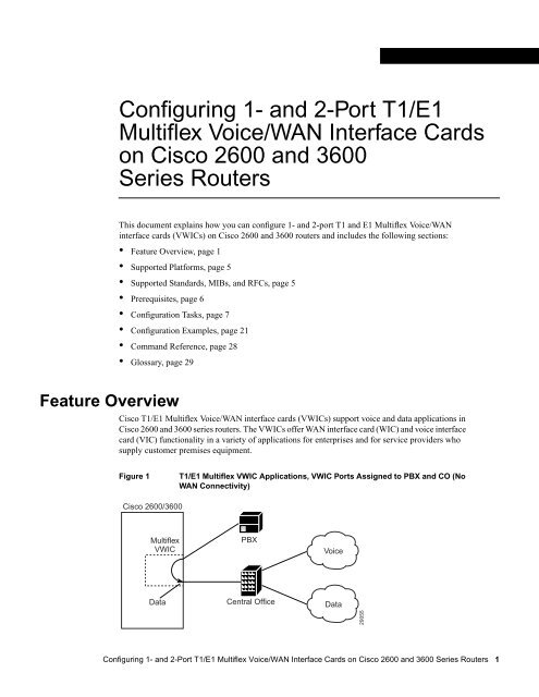
Cisco <strong>T1</strong>/<strong>E1</strong> <strong>Multiflex</strong> <strong>Voice</strong>/<strong>WAN</strong> interface cards (VWICs) support voice <strong>and</strong> data applications in<br />
Cisco 2600 <strong>and</strong> 3600 series routers. The VWICs offer <strong>WAN</strong> interface card (WIC) <strong>and</strong> voice interface<br />
card (VIC) functionality in a variety of applications for enterprises <strong>and</strong> for service providers who<br />
supply customer premises equipment.<br />
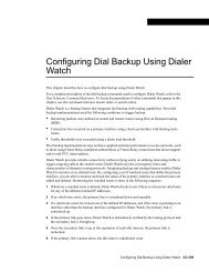
Figure 1<br />
<strong>T1</strong>/<strong>E1</strong> <strong>Multiflex</strong> VWIC Applications, VWIC <strong>Port</strong>s Assigned to PBX <strong>and</strong> CO (No<br />
<strong>WAN</strong> Connectivity)<br />
Cisco 2600/3600<br />
<strong>Multiflex</strong><br />
VWIC<br />
PBX<br />
<strong>Voice</strong><br />
Data<br />
Central Office<br />
Data<br />
29055<br />
<strong>Configuring</strong> 1- <strong>and</strong> 2-<strong>Port</strong> <strong>T1</strong>/<strong>E1</strong> <strong>Multiflex</strong> <strong>Voice</strong>/<strong>WAN</strong> Interface Cards on Cisco 2600 <strong>and</strong> 3600 Series Routers 1
Feature Overview<br />
<strong>Multiflex</strong> VWICs support the following applications:<br />
• Data: As WICs for <strong>T1</strong>/<strong>E1</strong> applications, including fractional use, the <strong>T1</strong> version integrates a fully<br />
managed data service unit/channel service unit (DSU/CSU), <strong>and</strong> the <strong>E1</strong> version includes a fully<br />
managed DSU.<br />
• Packet <strong>Voice</strong>: As VICs included with the Digital <strong>T1</strong> Packet <strong>Voice</strong> T<strong>ru</strong>nk Network Module to<br />
provide <strong>T1</strong> connections to private branch exchanges (PBXs) <strong>and</strong> central offices (COs), the <strong>T1</strong><br />
VWICs enable packet voice over IP (VoIP) applications.<br />
• Multiplexed <strong>Voice</strong> <strong>and</strong> Data: 2-port <strong>T1</strong>/<strong>E1</strong> VWICs can provide Drop-<strong>and</strong>-Insert multiplexing<br />
services with integrated DSU/CSUs. For example, when used with a Digital <strong>T1</strong> Packet <strong>Voice</strong><br />
T<strong>ru</strong>nk Network Module, Drop <strong>and</strong> Insert allows you to take 64Kb DS0 channels from one <strong>T1</strong> <strong>and</strong><br />
digitally cross-connect them to 64Kb DS0 channels on another <strong>T1</strong>. Drop <strong>and</strong> Insert, sometimes<br />
called Time-Division Multiplexing (TDM) Cross-Connect, uses circuit switching <strong>and</strong> does not use<br />
the digital signal processors (DSPs) that VoIP technology employs.<br />
The following <strong>Multiflex</strong> VWICs are available:<br />
• 1-port <strong>T1</strong> <strong>Multiflex</strong> T<strong>ru</strong>nk Interface (VWIC-1MFT-<strong>T1</strong>)<br />
• 1-port <strong>E1</strong> <strong>Multiflex</strong> T<strong>ru</strong>nk Interface (VWIC-1MFT-<strong>E1</strong>)<br />
• 2-port <strong>T1</strong> <strong>Multiflex</strong> T<strong>ru</strong>nk Interface (VWIC-2MFT-<strong>T1</strong>)<br />
• 2-port <strong>E1</strong> <strong>Multiflex</strong> T<strong>ru</strong>nk Interface (VWIC-2MFT-<strong>E1</strong>)<br />
• 2-port <strong>T1</strong> <strong>Multiflex</strong> T<strong>ru</strong>nk Interface with Drop <strong>and</strong> Insert (VWIC-2MFT-<strong>T1</strong>-DI)<br />
• 2-port <strong>E1</strong> <strong>Multiflex</strong> T<strong>ru</strong>nk Interface with Drop <strong>and</strong> Insert (VWIC-2MFT-<strong>E1</strong>-DI)<br />
<strong>Multiflex</strong> VWIC features include:<br />
• Drop-<strong>and</strong>-Insert capabilities that allow individual 64Kb DS0 channels to be transparently passed,<br />
uncompressed, between two ports on the same <strong>Multiflex</strong> VWIC without passing through a digital<br />
signal processor (DSP):<br />
— By using this method, the channel traffic is sent between a PBX <strong>and</strong> central office (CO) or<br />
other telephony device.<br />
— In addition, Drop <strong>and</strong> Insert can cross-connect a telephony switch (from the CO or PSTN) to<br />
a channel bank to provide external analog connectivity.<br />
Note<br />
<strong>T1</strong>/<strong>E1</strong> channels can be used either for Drop <strong>and</strong> Insert or VoIP, but not both.<br />
• Physical-layer alarm forwarding feature between the ports on 2-port cards<br />
• <strong>T1</strong>/<strong>E1</strong> or fractional <strong>T1</strong>/<strong>E1</strong> network interfaces<br />
• Per-channel <strong>T1</strong>/<strong>E1</strong> data rates of 64 or 56 kbps for <strong>WAN</strong> services (Frame Relay or leased line)<br />
2 Cisco IOS Release 12.0(7)T
Benefits<br />
Table 1<br />
Table 1 shows the possible hardware configurations for the <strong>Multiflex</strong> VWICs.<br />
<strong>Multiflex</strong> VWIC Support<br />
VWIC <strong>and</strong><br />
Application Cisco 2600 Series Cisco 3620 <strong>and</strong> 3640 Cisco 3660<br />
1-port<br />
Data only<br />
2-port<br />
Data only<br />
2-port<br />
Drop-<strong>and</strong>-Insert<br />
1- or 2-port<br />
<strong>Voice</strong> only, no<br />
<strong>WAN</strong><br />
connections<br />
<strong>T1</strong> or <strong>E1</strong> VWIC in a chassis slot<br />
<strong>T1</strong> or <strong>E1</strong> VWIC in a chassis slot. Does not<br />
provide packet voice. Can provide two<br />
physical <strong>WAN</strong> connections with both<br />
ports supporting up to full <strong>T1</strong>/<strong>E1</strong> speeds.<br />
<strong>T1</strong> or <strong>E1</strong> D&I VWIC in a chassis slot.<br />
Does not provide packet voice. Provides<br />
<strong>WAN</strong> connections <strong>and</strong> digital<br />
cross-connect.<br />
<strong>T1</strong> VWIC in a Digital <strong>T1</strong> Packet <strong>Voice</strong><br />
T<strong>ru</strong>nk Network Module<br />
<strong>T1</strong> or <strong>E1</strong> VWIC in a 1- or 2-port network<br />
module (NM-1E2W, NM-2E2W,<br />
NM-1<strong>E1</strong>R2W)<br />
Planned for future availability<br />
<strong>T1</strong> D&I VWIC in a Digital <strong>T1</strong> Packet<br />
<strong>Voice</strong> T<strong>ru</strong>nk Network Module. Provides<br />
voice connections <strong>and</strong> digital<br />
cross-connect. Does not provide <strong>WAN</strong><br />
connections.<br />
<strong>T1</strong> or <strong>E1</strong> D&I VWIC in a 1- or 2-port<br />
network module (NM-1E2W, NM-2E2W,<br />
NM-1<strong>E1</strong>R2W). Provides <strong>WAN</strong><br />
connections <strong>and</strong> digital cross-connect.<br />
<strong>T1</strong> VWIC in a Digital <strong>T1</strong> Packet <strong>Voice</strong><br />
T<strong>ru</strong>nk Network Module<br />
Planned for future availability<br />
Planned for future availability<br />
<strong>T1</strong> D&I VWIC in a Digital <strong>T1</strong><br />
Packet <strong>Voice</strong> T<strong>ru</strong>nk Network<br />
Module. Provides voice<br />
connections <strong>and</strong> digital<br />
cross-connect. Does not<br />
provide <strong>WAN</strong> connections.<br />
<strong>T1</strong> VWIC in a Digital <strong>T1</strong><br />
Packet <strong>Voice</strong> T<strong>ru</strong>nk Network<br />
Module<br />
Benefits<br />
<strong>T1</strong>/<strong>E1</strong> <strong>Multiflex</strong> VWICs reduce networking life-cycle costs in the following ways:<br />
• Allow an efficient transition from data-only applications to both multiplexed voice <strong>and</strong> data <strong>and</strong><br />
packet voice applications.<br />
• Are easier to deploy <strong>and</strong> manage than single-purpose interfaces.<br />
<strong>T1</strong>/<strong>E1</strong> <strong>Multiflex</strong> VWICs provide the following benefits of multifunction support for LAN-to-LAN<br />
routing, multiplexed voice <strong>and</strong> data, <strong>and</strong> voice:<br />
• Eliminate costly external CSUs or DSUs.<br />
• Eliminate the need for Drop-<strong>and</strong>-Insert multiplexers.<br />
• Simplify remote network management by allowing a single management tool, such as CiscoView<br />
or CiscoWorks, to support router, CSU/DSU, Drop-<strong>and</strong>-Insert multiplexer functions.<br />
• Increase <strong>T1</strong>/<strong>E1</strong> port density supported on Cisco 2600 series routers <strong>and</strong> permit two <strong>T1</strong>/<strong>E1</strong><br />
connections in a single WIC slot.<br />
<strong>Configuring</strong> 1- <strong>and</strong> 2-<strong>Port</strong> <strong>T1</strong>/<strong>E1</strong> <strong>Multiflex</strong> <strong>Voice</strong>/<strong>WAN</strong> Interface Cards on Cisco 2600 <strong>and</strong> 3600 Series Routers 3
Feature Overview<br />
Restrictions<br />
The following restrictions apply to <strong>T1</strong>/<strong>E1</strong> <strong>Multiflex</strong> VWIC configurations:<br />
• On Cisco 3660 platforms, <strong>Multiflex</strong> VWICs are supported only when they are installed in a<br />
Digital <strong>T1</strong> Packet <strong>Voice</strong> T<strong>ru</strong>nk Network Module.<br />
• On all Cisco 2600 <strong>and</strong> 3600 platforms, Digital <strong>T1</strong> Packet <strong>Voice</strong> T<strong>ru</strong>nk Network Modules only<br />
support <strong>T1</strong> <strong>Multiflex</strong> VWICs.<br />
• <strong>E1</strong> VWICs are not supported on Cisco 3660 platforms.<br />
• Cisco 3620 <strong>and</strong> 3640 combination network modules allow the installation of either a 1-port<br />
VWIC or a 2-port Drop-<strong>and</strong>-Insert VWIC.<br />
• Drop-<strong>and</strong>-Insert capability is supported only between two ports on the same multiflex card.<br />
• When installed in a Cisco 2600 chassis slot, DSP resources for packet voice are not available to<br />
the <strong>Multiflex</strong> VWICs with Drop <strong>and</strong> Insert.<br />
See Table 1 on page 3 for summary information.<br />
Related Features <strong>and</strong> Technologies<br />
Digital <strong>T1</strong> Packet <strong>Voice</strong> T<strong>ru</strong>nk Network Modules requires 2-port <strong>T1</strong> <strong>Multiflex</strong> VWIC for operation.<br />
For more information about these modules, see <strong>Configuring</strong> Digital <strong>T1</strong> Packet <strong>Voice</strong> T<strong>ru</strong>nk Network<br />
Modules on Cisco 2600 <strong>and</strong> 3600 Series Routers.<br />
Related Documents<br />
The following documents provide additional information about installing <strong>and</strong> configuring <strong>T1</strong>/<strong>E1</strong><br />
<strong>Multiflex</strong> VWICs:<br />
• Cisco 2600 <strong>and</strong> 3600 Series Network Module Hardware Installation Guide<br />
• Cisco 2600 <strong>and</strong> 3600 Series <strong>WAN</strong> Interface Cards Hardware Installation Guide<br />
• <strong>Configuring</strong> Digital <strong>T1</strong> Packet <strong>Voice</strong> T<strong>ru</strong>nk Network Modules on Cisco 2600 <strong>and</strong> 3600 Series<br />
Routers<br />
The following Cisco IOS Release 12.0 documents provide information that can help you use <strong>T1</strong>/<strong>E1</strong><br />
<strong>Multiflex</strong> VWICs:<br />
• <strong>Voice</strong>, Video, <strong>and</strong> Home Applications Configuration Guide<br />
• <strong>Voice</strong>, Video, <strong>and</strong> Home Applications Comm<strong>and</strong> Reference<br />
• Network Protocols Configuration Guide, Part 1<br />
• Cisco IOS Interface Configuration Guide<br />
• Cisco IOS Interface Comm<strong>and</strong> Reference<br />
• Dial Solutions Configuration Guide<br />
4 Cisco IOS Release 12.0(7)T
Supported Platforms<br />
Supported Platforms<br />
This feature is supported on the following platforms:<br />
• Cisco 2610<br />
• Cisco 2611<br />
• Cisco 2612<br />
• Cisco 2613<br />
• Cisco 2620<br />
• Cisco 2621<br />
• Cisco 3620<br />
• Cisco 3640<br />
• Cisco 3661<br />
• Cisco 3662<br />
Supported St<strong>and</strong>ards, MIBs, <strong>and</strong> RFCs<br />
<strong>T1</strong>/<strong>E1</strong> <strong>Multiflex</strong> VWICs support the st<strong>and</strong>ards, MIBs, <strong>and</strong> RFCs listed in this section.<br />
<strong>T1</strong> Compliance (Partial List)<br />
• ANSI <strong>T1</strong>.403<br />
• US (UL 1950, <strong>T1</strong>)<br />
• FCC Part 68<br />
• CS-03<br />
• Canada (CSA 950, <strong>T1</strong>)<br />
• US (FCC Part 15 Class B, <strong>T1</strong>)<br />
• U.K. (BS6301, EN60950, EN41003)<br />
• Canada (CSA C108.8 Class A, <strong>T1</strong>)<br />
• Bellcore---AT&T Accunet (62411)<br />
• ATT 54016<br />
• Japan (VCCI Class 2, VCCI:V-3/97.04, <strong>T1</strong>, JATE Green Book, IEC950)<br />
<strong>E1</strong> Compliance (Partial List)<br />
• Australia (TS 016, AS/NZS 3548:1995)<br />
• Germany (TUV GS, EN60950)<br />
• Germany (VDE 0878 part 3 <strong>and</strong> 30)<br />
• France (NFC98020, EN60950, EN41003)<br />
• Sweden (SS447-2-22, SS636334, EN60950)<br />
<strong>Configuring</strong> 1- <strong>and</strong> 2-<strong>Port</strong> <strong>T1</strong>/<strong>E1</strong> <strong>Multiflex</strong> <strong>Voice</strong>/<strong>WAN</strong> Interface Cards on Cisco 2600 <strong>and</strong> 3600 Series Routers 5
Prerequisites<br />
• UK (NTR4)<br />
• Europe (EN55022 Class B, EN55102-1, EN55102-2, CTR12, EN60950, EN50082-1:1992,<br />
EN55022:1994)<br />
• CCITT/ITU G.704, I.431<br />
• ETSI NET5, ETS300156<br />
• TBR4<br />
• CTR-13<br />
• ETS 300011<br />
• ITU I.431<br />
RFC<br />
RFC 1406<br />
MIB<br />
• <strong>T1</strong> CSU MIB<br />
Other St<strong>and</strong>ards<br />
• ANSI <strong>T1</strong>.40<br />
• AT&T Publication 62411<br />
Prerequisites<br />
<strong>T1</strong>/<strong>E1</strong> <strong>Multiflex</strong> VWICs require specific service, software, <strong>and</strong> hardware:<br />
• Obtain <strong>T1</strong> or <strong>E1</strong> service from your service provider.<br />
• Install Cisco IOS Software Release 12.0(5)XK, 12.0(7)T or a later release.<br />
• If you are installing <strong>Multiflex</strong> VWICs in a Digital <strong>T1</strong> Packet <strong>Voice</strong> T<strong>ru</strong>nk Network Module, see<br />
the following documents for more information about the module:<br />
— Cisco 2600 <strong>and</strong> 3600 Series Network Module Hardware Installation Guide<br />
— <strong>Configuring</strong> Digital <strong>T1</strong> Packet <strong>Voice</strong> T<strong>ru</strong>nk Network Modules on Cisco 2600 <strong>and</strong> 3600 Series<br />
Routers<br />
Note You can install one Digital <strong>T1</strong> Packet <strong>Voice</strong> T<strong>ru</strong>nk Network Module in a Cisco 2600 series<br />
router or a Cisco 3620 router. A Cisco 3640 router can support three modules, <strong>and</strong> you can install<br />
as many as six modules in a Cisco 3660 router.<br />
6 Cisco IOS Release 12.0(7)T<br />
• Install the <strong>T1</strong> or <strong>E1</strong> <strong>Multiflex</strong> VWIC by following the inst<strong>ru</strong>ctions in Cisco 2600 <strong>and</strong> 3600 Series<br />
<strong>WAN</strong> Interface Cards Hardware Installation Guide.<br />
• If you are using Drop <strong>and</strong> Insert with a Digital <strong>T1</strong> Packet <strong>Voice</strong> T<strong>ru</strong>nk Network Module, install<br />
at least one other network module or <strong>WAN</strong> interface card to provide the connection to the IP LAN<br />
or <strong>WAN</strong>.
Configuration Tasks<br />
• Establish a working IP network. For more information about configuring IP, see “IP Overview,”<br />
“<strong>Configuring</strong> IP Addressing,” <strong>and</strong> “<strong>Configuring</strong> IP Services” chapters in the Cisco IOS Release<br />
12.0 Network Protocols Configuration Guide, Part 1.<br />
• Complete your company’s dial plan.<br />
• Establish a working telephony network based on your company's dial plan.<br />
<strong>Voice</strong>, Video, <strong>and</strong> Home Applications Configuration Guide <strong>and</strong> <strong>Voice</strong>, Video, <strong>and</strong> Home Applications<br />
Comm<strong>and</strong> Reference for Cisco IOS Release 12.0 provide information about setting up voice<br />
networks.<br />
Configuration Tasks<br />
<strong>Configuring</strong> <strong>T1</strong>/<strong>E1</strong> <strong>Multiflex</strong> VWICs includes the following tasks:<br />
• Setting up voice cards (voice only) <strong>and</strong> <strong>T1</strong>/<strong>E1</strong> controllers.<br />
• <strong>Configuring</strong> serial <strong>and</strong> LAN interfaces.<br />
• Setting up voice ports (voice services applying only to <strong>T1</strong> <strong>Multiflex</strong> VWICs installed in Digital<br />
<strong>T1</strong> Packet <strong>Voice</strong> T<strong>ru</strong>nk Network Module).<br />
• <strong>Configuring</strong> voice dial peers (voice services applying only to <strong>T1</strong> <strong>Multiflex</strong> VWICs installed in<br />
Digital <strong>T1</strong> Packet <strong>Voice</strong> T<strong>ru</strong>nk Network Modules).<br />
For detailed information about configuring a <strong>T1</strong> <strong>Multiflex</strong> VWIC that is installed in a Digital <strong>T1</strong><br />
Packet <strong>Voice</strong> T<strong>ru</strong>nk Network Module, see <strong>Configuring</strong> Digital <strong>T1</strong> Packet <strong>Voice</strong> T<strong>ru</strong>nk Network<br />
Modules on Cisco 2600 <strong>and</strong> 3600 Series Routers.<br />
<strong>Configuring</strong> <strong>Voice</strong> Card <strong>and</strong> Controller Settings<br />
This section includes the following sections:<br />
• <strong>Configuring</strong> voice cards <strong>and</strong> DS0 groups, only for <strong>T1</strong> <strong>Multiflex</strong> VWICs installed in Digital <strong>T1</strong><br />
Packet <strong>Voice</strong> T<strong>ru</strong>nk Network Modules when voice services are required<br />
• <strong>Configuring</strong> <strong>T1</strong> or <strong>E1</strong> controllers<br />
• <strong>Configuring</strong> Drop <strong>and</strong> Insert for <strong>T1</strong> or <strong>E1</strong><br />
<strong>Configuring</strong> 1- <strong>and</strong> 2-<strong>Port</strong> <strong>T1</strong>/<strong>E1</strong> <strong>Multiflex</strong> <strong>Voice</strong>/<strong>WAN</strong> Interface Cards on Cisco 2600 <strong>and</strong> 3600 Series Routers 7
Configuration Tasks<br />
<strong>Configuring</strong> <strong>Voice</strong> Cards <strong>and</strong> DS0 Groups<br />
Follow the steps below if you are configuring <strong>T1</strong> <strong>Multiflex</strong> VWICs installed in Digital <strong>T1</strong> Packet<br />
<strong>Voice</strong> T<strong>ru</strong>nk Network Modules for voice. Repeat Steps 2 <strong>and</strong> 3 for each voice card.<br />
Step Comm<strong>and</strong> Purpose<br />
1 Router# configure terminal Enter global configuration mode.<br />
2 Router(config)# voice-card slot Enter voice card interface configuration mode <strong>and</strong> specify<br />
the slot location by using a value from 0 to 5, depending<br />
upon your router.<br />
3 Router(config-voice-ca)# codec complexity {high |<br />
medium}<br />
Specify the codec complexity based on the codec st<strong>and</strong>ard<br />
you are using. High-complexity codecs support lower call<br />
density than do medium-complexity codecs. The number<br />
of channels supported is based on the number of packet<br />
voice data modules (PVDMs) installed <strong>and</strong> the codec<br />
complexity. Here is a guideline:<br />
• In high-complexity codec mode, up to six voice or fax<br />
calls can be completed per PVDM-12, using the<br />
following codecs: G.711, G.726, G.729, G.729 Annex<br />
B, G.723.1, G.723.1 Annex A, G.728, <strong>and</strong> fax relay.<br />
• In medium-complexity codec mode, up to twelve voice<br />
or fax calls can be completed per PVDM-12, using the<br />
following codecs: G.711, G.726, G.729 Annex A,<br />
G.729 Annex B with Annex A, <strong>and</strong> fax relay<br />
All voice cards in a router must use the same codec<br />
complexity setting.<br />
The keyword that you specify for codec complexity<br />
affects the choice of codecs available using the codec<br />
dial-peer configuration comm<strong>and</strong>. See Step 7 in<br />
“<strong>Configuring</strong> <strong>Voice</strong> Dial Peers” on page 17.<br />
You cannot change codec complexity while DS0 groups<br />
are defined. If they are already set up, use the no<br />
ds0-group comm<strong>and</strong> before resetting the codec<br />
complexity. For more information about the ds0-group<br />
comm<strong>and</strong>, see Step 5.<br />
4 Router(config)# controller <strong>T1</strong> slot/port Enter controller configuration mode for the VWIC. Valid<br />
values for slot are 0 through 5 <strong>and</strong> for port are 0 <strong>and</strong> 1.<br />
8 Cisco IOS Release 12.0(7)T
<strong>Configuring</strong> <strong>Voice</strong> Card <strong>and</strong> Controller Settings<br />
Step Comm<strong>and</strong> Purpose<br />
5 Router(config-controller)# ds0-group ds0-group-no<br />
timeslots timeslot-list type {e&m-immediate |<br />
e&m-delay |e&m-wink | fxs-ground-start |<br />
fxs-loop-start | fxo-ground-start | fxo-loop-start}<br />
(<strong>Voice</strong> only) This comm<strong>and</strong> defines the <strong>T1</strong> channels for<br />
use by compressed voice calls as well as the signaling<br />
method the router uses to connect to the PBX or CO. Set<br />
up DS0 groups after you have specified codec complexity<br />
in voice-card configuration, as shown in Step 3. If you<br />
modify the codec complexity comm<strong>and</strong> parameters, you<br />
must first remove any existing DS0 groups, then reinstate<br />
them after the change to the codec complexity.<br />
ds0-group-no is a value from 0 to 23 that identifies the<br />
DS0 group.<br />
Note The ds0-group comm<strong>and</strong> automatically creates a<br />
logical voice port that is numbered as follows:<br />
slot/port:ds0-group-no. Although only one voice port is<br />
created, applicable calls are routed to any channel in the<br />
group.<br />
timeslot-list is a single number, numbers separated by<br />
commas, or a pair of numbers separated by a hyphen to<br />
indicate a range of timeslots. For <strong>T1</strong>, allowable values are<br />
from 1 to 24. To map individual DS0 timeslots, define<br />
additional groups. The system maps additional voice ports<br />
for each defined group. See Step 2 of “<strong>Configuring</strong> <strong>Voice</strong><br />
<strong>Port</strong>s” on page 15.<br />
The signaling method selection for type depends on the<br />
connection that you are making:<br />
• The E&M interface allows connection for PBX t<strong>ru</strong>nk<br />
lines (tie lines) <strong>and</strong> telephone equipment. The wink <strong>and</strong><br />
delay settings both specify confirming signals between<br />
the transmitting <strong>and</strong> receiving ends, whereas the<br />
immediate setting stipulates no special offhook/onhook<br />
signals.<br />
• The FXO interface is for connection of a central office<br />
(CO) to a st<strong>and</strong>ard PBX interface where permitted by<br />
local regulations; the interface is often used for<br />
off-premises extensions.<br />
• The FXS interface allows connection of basic telephone<br />
equipment <strong>and</strong> PBXs.<br />
<strong>Configuring</strong> 1- <strong>and</strong> 2-<strong>Port</strong> <strong>T1</strong>/<strong>E1</strong> <strong>Multiflex</strong> <strong>Voice</strong>/<strong>WAN</strong> Interface Cards on Cisco 2600 <strong>and</strong> 3600 Series Routers 9
Configuration Tasks<br />
<strong>Configuring</strong> <strong>T1</strong> <strong>and</strong> <strong>E1</strong> Controllers<br />
Follow this procedure to configure <strong>T1</strong> <strong>and</strong> <strong>E1</strong> controllers. Skip Steps 1 <strong>and</strong> 2 if you are already in<br />
controller configuration mode.<br />
Repeat the steps following Step 2 for each controller.<br />
1 Router# configure terminal Skip this step if you are already in controller configuration<br />
mode.<br />
Enter global configuration mode.<br />
2 Router(config)# controller {<strong>T1</strong> | <strong>E1</strong>}slot/port Skip this step if you are already in controller configuration<br />
mode.<br />
Enter controller configuration mode for the <strong>T1</strong> or <strong>E1</strong><br />
controller at the specified slot/port location.<br />
3 Router(config-controller)# loopback {diagnostic |<br />
local {payload | line}|remote {iboc |esf {payload | line}}<br />
4 Router(config-controller)# clock source {line<br />
[primary] | internal}<br />
5 Router(config-controller)# framing {sf | esf}<br />
or<br />
Router(config-controller)# framing {crc4 | no-crc4}<br />
[australia]<br />
(Optional, <strong>T1</strong> only, testing) This comm<strong>and</strong> generates a<br />
local loopback test at the line or payload level or a remote<br />
loopback. For details, <strong>Configuring</strong> Digital <strong>T1</strong> Packet<br />
<strong>Voice</strong> T<strong>ru</strong>nk Network Modules on Cisco 2600 <strong>and</strong> 3600<br />
Series Routers.<br />
Specify the clock source. The line keyword specifies that<br />
the clock source is derived from the active line—rather<br />
than from the free-<strong>ru</strong>nning internal clock. This is the<br />
default setting <strong>and</strong> is generally more reliable. These <strong>ru</strong>les<br />
apply to clock sourcing:<br />
• When both ports are set to line clocking with no<br />
primary specification, port 0 is the default primary<br />
clock source <strong>and</strong> port 1 is the default secondary clock<br />
source.<br />
• When both ports are set to line <strong>and</strong> one port is set as the<br />
primary clock source, the other port is by default the<br />
backup or secondary source <strong>and</strong> is loop-timed.<br />
• If one port is set to clock source line or clock source<br />
line primary <strong>and</strong> the other is set to clock source<br />
internal, the internal port recovers clock from the clock<br />
source line port if the clock source line port is up. If it is<br />
down, then the internal port generates its own clock.<br />
• If both ports are set to clock source internal, there is<br />
only one clock source—internal.<br />
Set the framing to SuperFrame (SF) or Extended<br />
SuperFrame (ESF) format, according to service provider<br />
requirements.<br />
Set the framing to cyclic redundancy check 4 (CRC4) or<br />
no CRC4, according to service provider requirements.<br />
The australia optional keyword specifies Australian<br />
Layer 1 Homologation for <strong>E1</strong> framing.<br />
10 Cisco IOS Release 12.0(7)T
<strong>Configuring</strong> <strong>Voice</strong> Card <strong>and</strong> Controller Settings<br />
6 Router(config-controller)# linecode {b8zs | ami | hdb3} Set the line encoding according to your service provider’s<br />
inst<strong>ru</strong>ctions. Bipolar-8 zero substitution (B8ZS), available<br />
only for <strong>T1</strong> lines, encodes a sequence of eight zeros in a<br />
unique binary sequence to detect line coding violations.<br />
Alternate mark inversion (AMI), available for <strong>T1</strong> or <strong>E1</strong><br />
lines, represents zeros using a 01 during each bit cell, <strong>and</strong><br />
ones are represented by 11 or 00, alternately, during each<br />
bit cell. AMI requires that the sending device maintain<br />
ones density. Ones density is not maintained independent<br />
of the data stream.<br />
For <strong>E1</strong>, set the line coding to either AMI or high-density<br />
bipolar 3 (HDB3), the default.<br />
7 Router(config-controller)# line-termination {75-ohm |<br />
120-ohm}<br />
(<strong>E1</strong> only) Enter a line-termination value. This comm<strong>and</strong><br />
specifies the impedance (amount of wire resistance <strong>and</strong><br />
reactivity to current) for the <strong>E1</strong> termination. Impedance<br />
levels are maintained to avoid data cor<strong>ru</strong>ption over<br />
long-distance links.<br />
Specify 120-ohm to match the balanced 120-ohm<br />
interface. This is the default.<br />
75-ohm is for an unbalanced BNC 75-ohm interface.<br />
8 Router(config-if)# fdl {att | ansi | both} (<strong>T1</strong> interfaces only) This comm<strong>and</strong> sets the Facility Data<br />
Link (FDL) exchange st<strong>and</strong>ard for the CSU controllers.<br />
The FDL is a 4-Kbps channel used with the Extended<br />
SuperFrame (ESF) framing format to provide out-of-b<strong>and</strong><br />
messaging for error-checking on a <strong>T1</strong> link.<br />
You typically leave this setting at the default, ansi, which<br />
follows the ANSI <strong>T1</strong>.403 st<strong>and</strong>ard for extended<br />
superframe facilities data link exchange support.<br />
Changing it allows improved management in some cases<br />
but can cause problems if your setting is not compatible<br />
with that of your service provider.<br />
att selects the AT&T TR54016 st<strong>and</strong>ard for extended<br />
superframe facilities data link exchange support.<br />
both enables both of the above st<strong>and</strong>ards.<br />
<strong>Configuring</strong> 1- <strong>and</strong> 2-<strong>Port</strong> <strong>T1</strong>/<strong>E1</strong> <strong>Multiflex</strong> <strong>Voice</strong>/<strong>WAN</strong> Interface Cards on Cisco 2600 <strong>and</strong> 3600 Series Routers 11
Configuration Tasks<br />
9 Router(config-controller)# cablelength long {gain26 |<br />
gain36} {-15db | -22.5db | -7.5db | 0db}<br />
or<br />
cablelength short {133 | 266 | 399 | 533 | 655}<br />
(<strong>T1</strong> interfaces only) The cable length setting must<br />
conform to the actual cable length you are using. For<br />
example, if you attempt to enter the cablelength short<br />
comm<strong>and</strong> on a long-haul <strong>T1</strong> link, the comm<strong>and</strong> is<br />
rejected.<br />
To set a cable length longer than 655 feet for a <strong>T1</strong> link,<br />
enter the cablelength long comm<strong>and</strong>:<br />
• gain26 specifies the decibel pulse gain at 26. This is the<br />
default pulse gain.<br />
• gain36 specifies the decibel pulse gain at 36.<br />
• -15db specifies the decibel pulse rate at -15 decibels.<br />
• -22.5db specifies the decibel pulse rate at -22.5<br />
decibels.<br />
• -7.5db specifies the decibel pulse rate at -7.5 decibels.<br />
• 0db specifies the decibel pulse rate at 0 decibels. This<br />
is the default pulse rate.<br />
To set a cable length 655 feet or less for a <strong>T1</strong> link, enter<br />
the cablelength short comm<strong>and</strong>. There is no default for<br />
cablelength short:<br />
• 133 specifies a cable length from 0-133 feet.<br />
• 266 specifies a cable length from 134-266 feet.<br />
• 399 specifies a cable length from 267-399 feet.<br />
• 533 specifies a cable length from 400-533 feet.<br />
• 655 specifies a cable length from 534-655 feet.<br />
If you do not set the cable length, the system defaults to a<br />
setting of cablelength long gain26 0db.<br />
<strong>Configuring</strong> Drop <strong>and</strong> Insert<br />
Perform the steps in this section if you are setting up Drop <strong>and</strong> Insert. If not, proceed to “<strong>Configuring</strong><br />
Serial Interfaces” on page 14.<br />
1 Router(config-controller)# tdm-group tdm-group-no<br />
timeslots timeslot-list type [e&m | fxs [loop-start |<br />
ground-start] fxo [loop-start | ground-start]<br />
Enter this comm<strong>and</strong> to set up TDM channel groups for the<br />
Drop-<strong>and</strong>-Insert function with a 2-port <strong>Multiflex</strong> VWIC.<br />
tdm-group-no is a value from 0 to 23 for <strong>T1</strong> <strong>and</strong> from 0 to<br />
30 for <strong>E1</strong>; it identifies the group.<br />
timeslot-list is a single number, numbers separated by<br />
commas, or a pair of numbers separated by a hyphen to<br />
indicate a range of timeslots. The valid range is from 1 to<br />
24 for <strong>T1</strong>. For <strong>E1</strong>, the range is from 1 to 31.<br />
The signaling method selection for type depends on the<br />
connection that you are making. The fxs <strong>and</strong> fxo options<br />
allow you to specify a ground-start or loop-start line. The<br />
Cisco IOS Release 12.0 <strong>Voice</strong>, Video, <strong>and</strong> Home<br />
Applications Comm<strong>and</strong> Reference includes additional<br />
information about these options.<br />
Note The group numbers for controller groups must be<br />
unique. For example, a TDM group should not have the<br />
same ID number as a DS0 group or channel group.<br />
12 Cisco IOS Release 12.0(7)T
Verifying <strong>Voice</strong> Card <strong>and</strong> Controller Settings<br />
2 Router(config-controller)# channel-group<br />
channel-group-no timeslots timeslot-list [speed<br />
[48|56|64]]<br />
3 Router(config-controller)# no shutdown Activate the controller.<br />
(Optional) Enter this comm<strong>and</strong> to set up channel groups<br />
for <strong>WAN</strong> data services with a 2-port <strong>Multiflex</strong><br />
Drop-<strong>and</strong>-Insert VWIC.<br />
channel-group-no is a value from 0 to 23 for <strong>T1</strong> <strong>and</strong> from<br />
0 to 30 for <strong>E1</strong>; because there can be only one channel<br />
group on a 1- or 2-port <strong>Multiflex</strong> VWIC, 0 is always the<br />
value.<br />
timeslot-list is a single number, numbers separated by<br />
commas, or a pair of numbers separated by a hyphen to<br />
indicate a range of timeslots. The valid range is from 1 to<br />
24 for <strong>T1</strong>. For <strong>E1</strong>, the range is from 1 to 31.<br />
The optional speed setting defaults to 56 Kbps for <strong>T1</strong> <strong>and</strong><br />
64 Kbps for <strong>E1</strong>.<br />
Note Although the CLI displays 48 as a speed option, it<br />
is not supported.<br />
4 Router(config-controller)# exit Exit controller configuration mode. Skip the next step if<br />
you are not setting up Drop <strong>and</strong> Insert.<br />
5 Router(config)# connect id {<strong>T1</strong> | <strong>E1</strong>} slot/port-1<br />
tdm-group-no-1 {<strong>T1</strong> | <strong>E1</strong>} slot/port-2 tdm-group-no-2<br />
This global configuration comm<strong>and</strong> sets up the<br />
connection between two <strong>T1</strong> or <strong>E1</strong> TDM groups of<br />
timeslots on the WVIC—for Drop <strong>and</strong> Insert.<br />
id is a name for the connection.<br />
Identify each controller by its slot/port location.<br />
tdm-group-no-1 <strong>and</strong> tdm-group-no-2 identify the TDM<br />
group numbers (from 0 to 23 or 30) on the specified<br />
controller. The groups were set up in Step 1.<br />
See the “Configuration Examples” section on page 21 for<br />
sample Drop <strong>and</strong> Insert configurations.<br />
Verifying <strong>Voice</strong> Card <strong>and</strong> Controller Settings<br />
Step 1<br />
Enter the show <strong>ru</strong>nning-config comm<strong>and</strong> to display the current voice-card setting. If no<br />
codec complexity is shown, the default of medium complexity is set. The following<br />
example shows an excerpt from the comm<strong>and</strong> output:<br />
Router# show <strong>ru</strong>nning-config<br />
.<br />
.<br />
hostname router-alpha<br />
voice-card 1<br />
codec complexity high<br />
.<br />
.<br />
.<br />
<strong>Configuring</strong> 1- <strong>and</strong> 2-<strong>Port</strong> <strong>T1</strong>/<strong>E1</strong> <strong>Multiflex</strong> <strong>Voice</strong>/<strong>WAN</strong> Interface Cards on Cisco 2600 <strong>and</strong> 3600 Series Routers 13
Configuration Tasks<br />
Step 2<br />
The privileged EXEC show controllers t1/e1 comm<strong>and</strong> displays the status of <strong>T1</strong> or <strong>E1</strong><br />
controllers <strong>and</strong> displays information about clock sources <strong>and</strong> other settings for the ports:<br />
Router# show controller <strong>T1</strong> 1/0<br />
<strong>T1</strong> 1/0 is up.<br />
Applique type is Channelized <strong>T1</strong><br />
Cablelength is short 133<br />
Description: <strong>T1</strong> WIC card Alpha<br />
No alarms detected.<br />
Framing is ESF, Line Code is B8ZS, Clock Source is Line Primary.<br />
Data in current interval (1 seconds elapsed):<br />
0 Line Code Violations, 0 Path Code Violations<br />
0 Slip Secs, 0 Fr Loss Secs, 0 Line Err Secs, 0 Degraded Mins<br />
0 Errored Secs, 0 Bursty Err Secs, 0 Severely Err Secs, 0 Unavail Secs<br />
Step 3<br />
The privileged EXEC show connection all comm<strong>and</strong> displays the status of <strong>T1</strong> or <strong>E1</strong><br />
TDM controller groups <strong>and</strong> how they are set up:<br />
Router# show connection all<br />
ID Name Segment 1 Segment 2 State<br />
========================================================================<br />
1 Test -<strong>T1</strong> 1/0 01 -<strong>T1</strong> 1/1 02 ADMIN UP<br />
<strong>Configuring</strong> Serial Interfaces<br />
The way you set up serial <strong>and</strong> LAN interfaces depends on your application. This document does not<br />
explain all possible serial interface configuration options, nor does it show LAN interface<br />
configuration. For complete information, see the Cisco IOS Release 12.0 Cisco IOS Interface<br />
Configuration Guide <strong>and</strong> the Cisco IOS Interface Comm<strong>and</strong> Reference.<br />
If you are not planning voice support, proceed to “Configuration Examples” on page 21.<br />
To configure VoIP, you must at least set up IP addresses for serial interfaces. When a user dials<br />
enough digits to match a configured destination pattern, the telephone number is mapped to an IP<br />
host through the dial plan mapper. The IP host has a direct connection to either the destination<br />
telephone number or a PBX that completes the call to the configured destination pattern.<br />
Note For information about monitoring serial interfaces in order to trigger a busy-out condition on<br />
a voice port when an interface is down, see “<strong>Configuring</strong> <strong>Voice</strong> <strong>Port</strong>s” on page 15.<br />
Step Comm<strong>and</strong> Purpose<br />
1 Router# configure terminal Enter global configuration mode.<br />
2 Router(config)# interface serial<br />
slot/port:channel-group<br />
Enter interface configuration mode for a serial interface<br />
that you specify by slot <strong>and</strong> port. The :channel-group<br />
portion of the comm<strong>and</strong> is only required for channelized<br />
<strong>T1</strong> or <strong>E1</strong> interfaces; its value is always 0 for <strong>Multiflex</strong><br />
VWIC support. (For setting up channelized interfaces, see<br />
Dial Solutions Configuration Guide for Cisco IOS<br />
Release 12.0.)<br />
3 Router(config-if)# ip address ip-address mask Assign the IP address <strong>and</strong> subnet mask to the interface.<br />
14 Cisco IOS Release 12.0(7)T
Verifying Serial Interface Configuration<br />
Verifying Serial Interface Configuration<br />
To verify serial interface configuration, enter the privileged EXEC comm<strong>and</strong> show interfaces serial,<br />
which shows the status of all serial interfaces or of a specific serial interface, as in the following<br />
example. You can use this comm<strong>and</strong> to check the encapsulation, IP addressing, <strong>and</strong> other settings:<br />
Router #show interface serial0/0:0<br />
Serial0/0:0 is up, line protocol is up<br />
Hardware is QUICC Serial<br />
Internet address is 1.156.1.1/24<br />
MTU 1500 bytes, BW 1536 Kbit, DLY 20000 usec,<br />
reliability 255/255, txload 1/255, rxload 1/255<br />
Encapsulation HDLC, loopback not set<br />
Keepalive not set<br />
Last input 00:00:00, output 00:00:00, output hang never<br />
Last clearing of "show interface" counters never<br />
Input queue: 0/75/0 (size/max/drops); Total output drops: 0<br />
Queueing strategy: weighted fair<br />
Output queue: 0/1000/64/0 (size/max total/threshold/drops)<br />
Conversations 0/1/256 (active/max active/max total)<br />
Reserved Conversations 0/0 (allocated/max allocated)<br />
5 minute input rate 1000 bits/sec, 1 packets/sec<br />
5 minute output rate 1000 bits/sec, 1 packets/sec<br />
637 packets input, 64736 bytes, 0 no buffer<br />
Received 181 broadcasts, 0 <strong>ru</strong>nts, 5 giants, 0 throttles<br />
3617 input errors, 1506 CRC, 1646 frame, 0 over<strong>ru</strong>n, 0 ignored, 0 abort<br />
682 packets output, 67213 bytes, 0 under<strong>ru</strong>ns<br />
0 output errors, 0 collisions, 1070 interface resets<br />
0 output buffer failures, 0 output buffers swapped out<br />
13 carrier transitions<br />
Timeslot(s) Used:1-24, Transmitter delay is 0 flags<br />
<strong>Configuring</strong> <strong>Voice</strong> <strong>Port</strong>s<br />
Follow these steps to set up voice ports to support the local <strong>and</strong> remote stations. This procedure<br />
applies only to <strong>T1</strong> <strong>Multiflex</strong> VWICs installed in Digital <strong>T1</strong> Packet <strong>Voice</strong> T<strong>ru</strong>nk Network Modules<br />
when voice services are required.<br />
This section does not show all the comm<strong>and</strong>s that you can use. To learn more, see <strong>Voice</strong>, Video, <strong>and</strong><br />
Home Applications Configuration Guide <strong>and</strong> <strong>Voice</strong>, Video, <strong>and</strong> Home Applications Comm<strong>and</strong><br />
Reference for Cisco IOS Release 12.0.<br />
Step Comm<strong>and</strong> Purpose<br />
1 Router# configure terminal Enter global configuration mode.<br />
<strong>Configuring</strong> 1- <strong>and</strong> 2-<strong>Port</strong> <strong>T1</strong>/<strong>E1</strong> <strong>Multiflex</strong> <strong>Voice</strong>/<strong>WAN</strong> Interface Cards on Cisco 2600 <strong>and</strong> 3600 Series Routers 15
Configuration Tasks<br />
Step Comm<strong>and</strong> Purpose<br />
2 Router(config)# voice-port slot/port:ds0-group-no Enter voice-port configuration mode.<br />
slot is the router location where the voice module is<br />
installed. Valid entries are from 0 to 3.<br />
port indicates the <strong>Multiflex</strong> VWIC location. Valid entries<br />
are 0 or 1.<br />
Each defined DS0 group number is represented on a<br />
separate voice port. This allows you to define individual<br />
DS0s on the digital <strong>T1</strong> card. For more information about<br />
DS0 groups, see Step 5 of “<strong>Configuring</strong> <strong>Voice</strong> Card <strong>and</strong><br />
Controller Settings” on page 7.<br />
Note This voice-port comm<strong>and</strong> syntax does not apply to<br />
analog voice network modules <strong>and</strong> voice interface cards.<br />
Specify voice interface cards by using slot/subunit/port,<br />
designating the router slot for the voice network module,<br />
the location of the voice interface card in the network<br />
module, <strong>and</strong> the port on the voice interface card.<br />
3 Router(config-voice-port)# busyout monitor interface<br />
interface number<br />
16 Cisco IOS Release 12.0(7)T<br />
(Optional) This comm<strong>and</strong> allows you to specify a LAN or<br />
<strong>WAN</strong> interface that will be monitored, <strong>and</strong>, when it is<br />
down, trigger a busyout (offhook) state on the voice port.<br />
This allows rerouting of calls. For example, if you specify<br />
Serial 1/0 as the interface <strong>and</strong> number, the voice port<br />
sends a busyout signal when that interface is down. You<br />
can issue the comm<strong>and</strong> repeatedly to specify as many<br />
interfaces, virtual interfaces, <strong>and</strong> subinterfaces as are<br />
required for a voice port.<br />
For example, if you issue the comm<strong>and</strong> three times so that<br />
three interfaces are monitored, the voice port only goes<br />
into busyout state when all three interfaces are down.<br />
When any one of the interfaces is operational, the busyout<br />
state is removed.<br />
4 Router(config-voice-port)# comfort-noise (Optional) This parameter is enabled by default. It creates<br />
subtle background noise to fill silent gaps during calls<br />
when VAD is enabled on voice dial peers. If comfort noise<br />
is not generated, the silence can be unsettling to callers.<br />
5 Router(config-voice-port)# echo-cancel enable (Optional) This setting is enabled by default. Echo<br />
cancellation adds to the quality of voice transmissions by<br />
adjusting the echo that occurs on the interface due to<br />
impedance mismatches. Some echo is reassuring; echo<br />
over 25 milliseconds can cause problems.<br />
6 Router(config-voice-port)# echo-cancel coverage {16 |<br />
24 |32 | 8}<br />
7 Router(config-voice-port)# connection {plar |t<strong>ru</strong>nk}<br />
string<br />
(Optional) This comm<strong>and</strong> adjusts the echo canceller by<br />
the specified number of milliseconds; the default is 16.<br />
(Optional) This comm<strong>and</strong> sets up a connection mode for<br />
the voice port.<br />
plar specifies a private line automatic ring down (PLAR)<br />
connection, which rings a remote telephone when the dial<br />
peer goes off hook.<br />
t<strong>ru</strong>nk specifies a straight tie-line connection to a PBX.<br />
string specifies the remote telephone number or<br />
significant start digits of the number.<br />
See “Configuration Examples” on page 21 for sample<br />
PLAR <strong>and</strong> t<strong>ru</strong>nk configurations.
Verifying <strong>Voice</strong> <strong>Port</strong>s<br />
Step Comm<strong>and</strong> Purpose<br />
8 Router(config-voice-port)# timeouts interdigit seconds (Optional) This comm<strong>and</strong> sets the number of seconds the<br />
system waits—after the caller has input the initial<br />
digit—for a subsequent digit of the dialed string. If the<br />
timeout ends before the destination is identified, a tone<br />
sounds <strong>and</strong> the call ends. The default value is 10 seconds,<br />
<strong>and</strong> the timeout can be set from 0 to 120 seconds.<br />
Note Changes to the default for this comm<strong>and</strong> normally<br />
are not required. Other timing settings may also be needed.<br />
For more information, see the Cisco IOS Release 12.0<br />
<strong>Voice</strong>, Video, <strong>and</strong> Home Applications Configuration<br />
Guide.<br />
9 Router(config-voice-port)# exit Exit voice-port configuration mode.<br />
Repeat Steps 2 through 9 for each DS0 group you create.<br />
Verifying <strong>Voice</strong> <strong>Port</strong>s<br />
Follow this procedure to verify voice-port configuration. To learn more, see Cisco IOS Release 12.0<br />
<strong>Voice</strong>, Video, <strong>and</strong> Home Applications Comm<strong>and</strong> Reference.<br />
Important comm<strong>and</strong> output is shown in bold.<br />
To verify the voice-port configuration, enter the privileged EXEC show voice port<br />
slot/port:ds0-group comm<strong>and</strong>. The following sample output from the comm<strong>and</strong> shows explanatory<br />
information after the
Configuration Tasks<br />
This section does not show all the comm<strong>and</strong>s that you might need to enter. To learn more, see <strong>Voice</strong>,<br />
Video, <strong>and</strong> Home Applications Configuration Guide <strong>and</strong> <strong>Voice</strong>, Video, <strong>and</strong> Home Applications<br />
Comm<strong>and</strong> Reference for Cisco IOS Release 12.0.<br />
Step Comm<strong>and</strong> Purpose<br />
1 Router# configure terminal Enter global configuration mode.<br />
2 Router(config)# dial-peer voice number pots Enter dial-peer configuration mode <strong>and</strong> define a local dial<br />
peer that will connect to the plain old telephone service<br />
(POTS) network.<br />
number is one or more digits identifying the dial peer.<br />
Valid entries are from 1 to 2147483647.<br />
pots indicates a peer using basic telephone service.<br />
3 Router(config-dialpeer)# destination-pattern string<br />
[T]<br />
Configure the dial peer's destination pattern, so that the<br />
system can reconcile dialed digits with a telephone<br />
number.<br />
string is a series of digits that specify the E.164 or private<br />
dialing plan phone number. Valid entries are the digits 0<br />
through 9 <strong>and</strong> the letters A through D. The plus symbol<br />
(+) is not valid. You can enter the following special<br />
characters:<br />
• The star character (*) that appears on st<strong>and</strong>ard<br />
touch-tone dial pads can be in any dial string but not as<br />
a leading character (for example, *650).<br />
• The period (.) acts as a wildcard character.<br />
• The comma (,) can be used only in prefixes <strong>and</strong> inserts<br />
a one-second pause.<br />
When the timer (T) character is included at the end of the<br />
destination pattern, the system collects dialed digits as<br />
they are entered—until the interdigit timer expires (10<br />
seconds, by default)—or the user dials the termination of<br />
end-of-dialing key (default is #).<br />
Note The timer character must be a capital T.<br />
4 Router(config-dialpeer)# prefix string (Optional) Include a dial-out prefix that the system enters<br />
automatically instead of people dialing it.<br />
string is a value from 0 to 9, <strong>and</strong> you can use a comma (,)<br />
to indicate a pause.<br />
Note There are other digit manipulation comm<strong>and</strong>s<br />
available to h<strong>and</strong>le such situations as prefixes for special<br />
services, ignoring some digits, <strong>and</strong> dialing in to remote<br />
PBXs as though they are local.<br />
5 Router(config-dialpeer)# port slot/port:ds0-group-no This comm<strong>and</strong> associates the dial peer with a specific<br />
logical interface.<br />
slot is the router location where the voice module is<br />
installed. Valid entries are from 0 to 3.<br />
port indicates the voice interface card location. Valid<br />
entries are 0 or 1.<br />
Each defined DS0 group number is represented on a<br />
separate voice port. This allows you to define individual<br />
DS0s on the digital <strong>T1</strong> card.<br />
18 Cisco IOS Release 12.0(7)T
<strong>Configuring</strong> <strong>Voice</strong> Dial Peers<br />
Step Comm<strong>and</strong> Purpose<br />
6 Router(config)# dial-peer voice number voip Enter dial-peer configuration mode <strong>and</strong> define a remote<br />
VoIP dial peer.<br />
number is one or more digits identifying the dial peer.<br />
Valid entries are from 1 to 2147483647.<br />
voip indicates a VoIP peer using voice encapsulation on<br />
the IP network.<br />
7 Router(config-dialpeer)# codec {g711alaw | g711ulaw |<br />
g723ar53 | g723ar63 | g723r53 | g723r63 | g726r16 |<br />
g726r24 | g726r32 | g728 | g729r8 [pre-ietf] | g729br8}<br />
[bytes]<br />
The voice-card configuration codec complexity<br />
comm<strong>and</strong> sets the codec options that are available when<br />
you enter this comm<strong>and</strong> (see Step 3 of “<strong>Configuring</strong> <strong>Voice</strong><br />
Card <strong>and</strong> Controller Settings” on page 7).<br />
If you do not set codec complexity, g729r8 with IETF<br />
bit-ordering is used.<br />
If you set codec complexity to high, the following options<br />
are available:<br />
• g711alaw—G.711 A Law 64,000 bps<br />
• g711ulaw—G.711 u Law 64,000 bps<br />
• g723ar53—G.723.1 Annex A 5,300 bps<br />
• g723ar63—G.723.1 Annex A 6,300 bps<br />
• g723r53—G.723.1 5,300 bps<br />
• g723r63—G.723.1 6,300 bps<br />
• g726r16—G.726 16,000 bps<br />
• g726r24—G.726 24,000 bps<br />
• g726r32—G.726 32,000 bps<br />
• g728—G.728 16,000 bps<br />
• g729r8---G.729 8,000 bps (default)<br />
• g729br8—G.729 Annex B 8,000 bps<br />
If you set codec complexity to medium, the following<br />
options are valid:<br />
• g711alaw—G.711 A Law 64,000 bps<br />
• g711ulaw—G.711 u Law 64,000 bps<br />
• g726r16—G.726 16,000 bps<br />
• g726r24—G.726 24,000 bps<br />
• g726r32—G.726 32,000 bps<br />
• g729r8—G.729 Annex A 8,000 bps<br />
• g729br8—G.729 Annex B with Annex A 8,000 bps<br />
The optional bytes parameter sets the number of voice<br />
data bytes per frame. Acceptable values are from 10 to<br />
240 in increments of 10 (for example, 10, 20, 30, <strong>and</strong> so<br />
on). Any other value is rounded down (for example, from<br />
236 to 230).<br />
If you specify g729r8, then Internet Engineering Task<br />
Force (IETF) bit-ordering is used. For interoperability<br />
with a Cisco 2600, 3600, or AS5300 router <strong>ru</strong>nning a<br />
Cisco IOS release earlier than Release 12.0(5)T<br />
or12.0(4)XH, you must specify the additional keyword<br />
pre-ietf after g729r8.<br />
<strong>Configuring</strong> 1- <strong>and</strong> 2-<strong>Port</strong> <strong>T1</strong>/<strong>E1</strong> <strong>Multiflex</strong> <strong>Voice</strong>/<strong>WAN</strong> Interface Cards on Cisco 2600 <strong>and</strong> 3600 Series Routers 19
Configuration Tasks<br />
Step Comm<strong>and</strong> Purpose<br />
8 Router(config-dialpeer)# vad (Optional) This setting is enabled by default <strong>and</strong> activates<br />
voice activity detection (VAD). VAD allows the system to<br />
reduce unnecessary voice transmissions caused by<br />
unfiltered background noise.<br />
9 Router(config-dialpeer)# dtmf-relay [cisco-rtp]<br />
[h245-signal] [h245-alphanumeric]<br />
10 Router(config-dialpeer)# fax-rate {2400 | 4800 | 7200<br />
| 9600 | 12000 | 14400 | disable | voice}<br />
11 Router(config-dialpeer)# destination-pattern string<br />
[T]<br />
12 Router(config-dialpeer)# session target<br />
{ipv4:destination-address | dns:[$s$. | $d$. | $e$. |<br />
$u$.] host-name}<br />
(Optional) Dual-tone multifrequency (DTMF) describes<br />
the tone that sounds in response to a keypress on a<br />
touch-tone phone. DTMF tones are compressed at one<br />
end of a call <strong>and</strong> decompressed at the other end.<br />
If a low-b<strong>and</strong>width codec, such as a G.729 or G.723 is<br />
used, the tones can sound distorted. The dtmf-relay<br />
comm<strong>and</strong> transports DTMF tones generated after call<br />
establishment out-of-b<strong>and</strong> by using a method that<br />
transmits with greater fidelity than is possible in-b<strong>and</strong> for<br />
most low-b<strong>and</strong>width codecs. Without DTMF relay, calls<br />
established with low-b<strong>and</strong>width codecs can have trouble<br />
accessing automated phone menu systems, such as voice<br />
mail <strong>and</strong> interactive voice response (IVR) systems.<br />
A signaling method is supplied only if the remote end<br />
supports it, <strong>and</strong> the options are: Cisco proprietary<br />
(cisco-rtp), st<strong>and</strong>ard H.323 (h245-alphanumeric), <strong>and</strong><br />
H.323 st<strong>and</strong>ard with signal duration (h245-signal).<br />
(Optional) Specify the transmission speed of a fax to be<br />
sent to this dial peer. disable turns off fax transmission<br />
capability, <strong>and</strong> voice specifies the highest possible fax<br />
speed supported by the voice rate.<br />
See Step 3 in this procedure.<br />
Configure the IP session target for the dial peer.<br />
ipv4:destination-address indicates IP address of the dial<br />
peer.<br />
dns:host-name indicates that the domain name server will<br />
resolve the name of the IP address. Valid entries for this<br />
parameter are characters representing the name of the host<br />
device.<br />
There are also wildcards available for defining domain<br />
names with the keyword by using source, destination, <strong>and</strong><br />
dialed information in the host name.<br />
For complete comm<strong>and</strong> syntax information, see <strong>Voice</strong>,<br />
Video, <strong>and</strong> Home Applications Comm<strong>and</strong> Reference for<br />
Cisco IOS Release 12.0.<br />
Verifying <strong>Voice</strong> Dial Peers<br />
Follow the procedure below to verify dial-peer configuration. To learn more about these comm<strong>and</strong>s,<br />
see <strong>Voice</strong>, Video, <strong>and</strong> Home Applications Comm<strong>and</strong> Reference for Cisco IOS Release 12.0.<br />
Important comm<strong>and</strong> output is shown in bold.<br />
Enter the privileged EXEC show dial-peer voice comm<strong>and</strong>. The following text is sample output<br />
from the comm<strong>and</strong> for a POTS dial peer:<br />
router# show dial-peer voice 1<br />
<strong>Voice</strong>EncapPeer1<br />
20 Cisco IOS Release 12.0(7)T
Configuration Examples<br />
tag = 1, dest-pat = \Q+14085551000',<br />
answer-address = \Q',<br />
group = 0, Admin state is up, Operation state is down<br />
Permission is Both,<br />
type = pots, prefix = \Q',<br />
session-target = \Q', voice-port =<br />
Connect Time = 0, Charged Units = 0<br />
Successful Calls = 0, Failed Calls = 0<br />
Accepted Calls = 0, Refused Calls = 0<br />
Last Disconnect Cause is "10"<br />
Last Disconnect Text is ""<br />
Last Setup Time = 0<br />
The following text is sample output from the show dial-peer voice comm<strong>and</strong> for a VoIP dial peer:<br />
Router# show dial-peer voice 10<br />
<strong>Voice</strong>OverIpPeer10<br />
tag = 10, dest-pat = \Q',<br />
incall-number = \Q+14087',<br />
group = 0, Admin state is up, Operation state is down<br />
Permission is Answer,<br />
type = voip, session-target = \Q',<br />
sess-proto = cisco, req-qos = bestEffort,<br />
acc-qos = bestEffort,<br />
fax-rate = voice, codec = g729r8,<br />
Expect factor = 10,Icpif = 30, VAD = disabled, Poor QOV Trap = disabled,<br />
Connect Time = 0, Charged Units = 0<br />
Successful Calls = 0, Failed Calls = 0<br />
Accepted Calls = 0, Refused Calls = 0<br />
Last Disconnect Cause is "10"<br />
Last Disconnect Text is ""<br />
Last Setup Time = 0<br />
Configuration Examples<br />
This section includes three sample configurations to illustrate different scenarios:<br />
• Drop <strong>and</strong> Insert where PSTN <strong>and</strong> VoIP services are provided through the same service provider line.<br />
• Drop <strong>and</strong> Insert where PSTN <strong>and</strong> data services are provided through the same service provider line.<br />
• Drop <strong>and</strong> Insert where PSTN, data, <strong>and</strong> VoIP services are provided through the same service provider<br />
line.<br />
Note For additional examples, see <strong>Configuring</strong> Digital <strong>T1</strong> Packet <strong>Voice</strong> T<strong>ru</strong>nk Network Modules on Cisco<br />
2600 <strong>and</strong> 3600 Series Routers.<br />
Drop-<strong>and</strong>-Insert technology is one way to integrate old PBX technologies with VoIP. It allows you to take<br />
64-Kb DS0 channels from one <strong>T1</strong> or <strong>E1</strong> <strong>and</strong> digitally cross-connect them to 64Kb DS0 channels on another<br />
<strong>T1</strong> or <strong>E1</strong>.<br />
Drop <strong>and</strong> Insert allows individual 64Kb DS0 channels to be transparently passed, uncompressed, between<br />
<strong>T1</strong>/<strong>E1</strong> ports without DSP processing. Channel traffic is sent between a PBX <strong>and</strong> CO switch or other<br />
telephony device, allowing the use, for example, of some PBX channels for long-distance service through<br />
the PSTN while the router compresses others for interoffice VoIP calls. In addition, Drop <strong>and</strong> Insert can<br />
cross-connect a telephony switch (from the CO or PSTN) to a channel bank to provide external analog<br />
connectivity.<br />
<strong>Configuring</strong> 1- <strong>and</strong> 2-<strong>Port</strong> <strong>T1</strong>/<strong>E1</strong> <strong>Multiflex</strong> <strong>Voice</strong>/<strong>WAN</strong> Interface Cards on Cisco 2600 <strong>and</strong> 3600 Series Routers 21
Configuration Examples<br />
Keep the following considerations in <strong>mind</strong>:<br />
• Drop <strong>and</strong> Insert works only between ports on the same <strong>Multiflex</strong> VWIC.<br />
• The VWIC can either be in a st<strong>and</strong>alone WIC slot on a Cisco 2600 series router, integrated into<br />
a Digital <strong>T1</strong> Packet <strong>Voice</strong> T<strong>ru</strong>nk Network Module VWIC slot, or installed in a Cisco 3600 series<br />
2-port network module (NM-1E2W, NM-2E2W, NM-1<strong>E1</strong>R2W).<br />
• When the VWIC module is installed in the VWIC slot of a Digital <strong>T1</strong> Packet <strong>Voice</strong> T<strong>ru</strong>nk<br />
Network Module, the <strong>T1</strong> ports do not provide <strong>WAN</strong> connectivity (for example. Frame-Relay,<br />
PPP, <strong>and</strong> so on) in addition to voice <strong>and</strong> Drop <strong>and</strong> Insert.<br />
• <strong>WAN</strong> <strong>and</strong> Drop-<strong>and</strong>-Insert capabilities are supported when the VWIC is in a chassis WIC slot on<br />
a Cisco 2600 series router.<br />
Drop <strong>and</strong> Insert with VoIP <strong>and</strong> PSTN Services<br />
Figure 2<br />
Sample Configuration: Drop <strong>and</strong> Insert with VoIP <strong>and</strong> PSTN Services<br />
PSTN<br />
<strong>T1</strong> 1 <strong>T1</strong> 1<br />
PBX<br />
<strong>T1</strong> 0 IP Network<br />
<strong>T1</strong> 0<br />
RTR-A<br />
RTR-B<br />
PBX<br />
26716<br />
Some PBX DS0s are used for PSTN services,<br />
while others are sent to the router for VoIP calls.<br />
This example in this section shows configuration for Drop <strong>and</strong> Insert when a 2-port <strong>Multiflex</strong> VWIC<br />
is installed in a Digital <strong>T1</strong> Packet <strong>Voice</strong> T<strong>ru</strong>nk Network Module VWIC slot <strong>and</strong> VoIP is configured.<br />
<strong>WAN</strong> connections must be provided by separate links.<br />
22 Cisco IOS Release 12.0(7)T
Drop <strong>and</strong> Insert with VoIP <strong>and</strong> PSTN Services<br />
hostname RTR-A<br />
!<br />
voice-card 1<br />
codec complexity high<br />
!<br />
controller <strong>T1</strong> 1/0<br />
framing esf<br />
linecoding b8zs<br />
ds0-group 1 timeslots 1-12 type e&m-wink<br />
tdm-group 2 timeslots 13-24 type e&m<br />
!<br />
controller <strong>T1</strong> 1/1<br />
framing esf<br />
linecoding b8zs<br />
clock source line primary<br />
tdm-group 3 timeslots 13-24 type e&m<br />
!<br />
voice-port 1/0:1<br />
!<br />
dial-peer voice 1 voip<br />
destination-pattern 4...<br />
codec g723r63<br />
dtmf-relay h245-alpha<br />
session target ipv4:209.165.200.253<br />
session target ipv4:209.165.200.252<br />
!<br />
dial-peer voice 2 pots<br />
destination-pattern 5...<br />
prefix 5<br />
port 1/0:1<br />
!<br />
interface serial 0/0<br />
encapsulation ppp<br />
ip address 209.165.200.252 255.255.255.224<br />
!<br />
connect tdm1 <strong>T1</strong> 1/0 2 <strong>T1</strong> 1/1 3<br />
hostname RTR-B<br />
!<br />
voice-card 1<br />
codec complexity high<br />
!<br />
controller <strong>T1</strong> 1/0<br />
framing esf<br />
linecoding b8zs<br />
ds0-group 1 timeslots 1-12 type e&m-wink<br />
tdm-group 2 timeslots 13-24 type e&m<br />
!<br />
controller <strong>T1</strong> 1/1<br />
framing esf<br />
linecoding b8zs<br />
clock source line primary<br />
tdm-group 3 timeslots 13-24 type e&m<br />
!<br />
voice-port 1/0:1<br />
!<br />
dial-peer voice 1 voip<br />
destination-pattern 5….<br />
codec g723r63<br />
dtmf-relay h245-alpha<br />
!<br />
!<br />
!<br />
dial-peer voice 2 pots<br />
destination-pattern 4….<br />
prefix 4<br />
port 1/0:1<br />
!<br />
interface serial 0/0<br />
encapsulation ppp<br />
ip address 209.165.200.253 255.255.255.224<br />
!<br />
connect tdm1 <strong>T1</strong> 1/0 2 <strong>T1</strong> 1/1 3<br />
Clock Sources<br />
In this example, two clock sources are available on each router’s <strong>Multiflex</strong> VWIC ports: one from<br />
the PBX <strong>and</strong> one from the PSTN central office (CO). However, the clock sources must be the same,<br />
so the system adjusts to this need.<br />
The primary keyword of the clock source comm<strong>and</strong>, applied to <strong>T1</strong> 1/1, means that the PSTN is<br />
providing the clock source. The <strong>T1</strong> 1/0 port connected to the PBX is automatically put into<br />
looped-time mode, which means that the port takes the clocking received on its Rx (receive) pair <strong>and</strong><br />
regenerates it back on its Tx (transmit) pair. While it is receiving clocking, it does not drive the<br />
on-board clock. It is “spoofing” the port so that the connected PBX does not detect clocking that is<br />
out of synchronization, which is indicated by slips. The router detects the slips as controlled <strong>and</strong> does<br />
not force the port to fail.<br />
<strong>Configuring</strong> 1- <strong>and</strong> 2-<strong>Port</strong> <strong>T1</strong>/<strong>E1</strong> <strong>Multiflex</strong> <strong>Voice</strong>/<strong>WAN</strong> Interface Cards on Cisco 2600 <strong>and</strong> 3600 Series Routers 23
Configuration Examples<br />
Additional Considerations<br />
Here are some additional key points for consideration:<br />
• The tdm-group 2 timeslots 13-24 type e&m comm<strong>and</strong> defines Drop <strong>and</strong> Insert by setting up the<br />
timeslots from each <strong>T1</strong> that will be used in the digital cross-connect. The type keyword is<br />
optional, but its use is specific to the Drop <strong>and</strong> Insert feature.<br />
— If you include the type keyword with a signaling type, the Drop-<strong>and</strong>-Insert cross-connect<br />
ensures that the specified signaling (on-hook <strong>and</strong> off-hook) is passed between the DS0s. It<br />
also uses the signaling bits to signal busy-out if one of the <strong>T1</strong>s goes down.<br />
— If you do not use the type keyword, the Drop-<strong>and</strong>-Insert cross-connect is clear channel <strong>and</strong><br />
does not interpret any signaling.<br />
• The connect tdm1 <strong>T1</strong> 1/0 2 <strong>T1</strong> 1/1 3 comm<strong>and</strong> activates the Drop-<strong>and</strong>-Insert digital<br />
cross-connect between the <strong>T1</strong>s. The tdm1 portion of the comm<strong>and</strong> is just a name for the<br />
cross-connect, <strong>and</strong> the name can be any word, number, or series of letters.<br />
• You can verify Drop-<strong>and</strong>-Insert connections by using the show connection comm<strong>and</strong>.<br />
Drop <strong>and</strong> Insert with Data <strong>and</strong> PSTN Services<br />
Figure 3<br />
Sample Configuration: Drop <strong>and</strong> Insert with Data <strong>and</strong> PSTN <strong>Voice</strong> Services<br />
PBX<br />
<strong>T1</strong><br />
RTR-A<br />
PSTN Services<br />
<strong>and</strong><br />
Frame-Relay Data<br />
RTR-B<br />
<strong>T1</strong><br />
PBX<br />
29053<br />
This example in this section shows configuration for Drop <strong>and</strong> Insert when a 2-port <strong>Multiflex</strong> VWIC<br />
is installed in a Cisco 2600 series chassis slot or in a WIC slot of a Cisco 3600 series network<br />
module. Frame Relay data <strong>and</strong> PSTN voice calls travel between the PBXs, but no VoIP or VoIP over<br />
Frame Relay information is carried.<br />
Clock Sources<br />
As in the previous example, two clock sources are available on each router’s <strong>Multiflex</strong> VWIC ports:<br />
one from the PBX <strong>and</strong> one from the PSTN central office (CO). However, the clock sources must be<br />
the same, so the system adjusts to this need.<br />
The primary clock source is <strong>T1</strong> or <strong>E1</strong> 1/0, connected to the PSTN, <strong>and</strong> its clock is a reference for<br />
<strong>T1</strong> or <strong>E1</strong> 1/1. If <strong>T1</strong> 1/0 fails, the clock source to drive <strong>T1</strong> or <strong>E1</strong> 1/1 is generated from the line to the<br />
PBX.<br />
Additional Considerations<br />
The channel-group 0 comm<strong>and</strong> is configured in such a way that the service provider can send<br />
Frame-Relay link management information (LMI) on <strong>T1</strong> channels 13 through 24 (17 through 31 on<br />
<strong>E1</strong>) for Frame-Relay data services. This comm<strong>and</strong> automatically creates interface serial 1/0:0.<br />
24 Cisco IOS Release 12.0(7)T
Drop <strong>and</strong> Insert with Data <strong>and</strong> PSTN Services<br />
Interface serial 1/0:0 is where all <strong>WAN</strong> <strong>and</strong> Layer 3 protocol details are configured, for example,<br />
Frame Relay encapsulation or IP addresses.<br />
<strong>T1</strong> Configuration<br />
hostname RTR-A<br />
!<br />
controller <strong>T1</strong> 1/0<br />
framing esf<br />
linecoding b8zs<br />
clock source line primary<br />
tdm-group 1 timeslots 1-12<br />
channel-group 0 timeslots 13-24<br />
!<br />
controller <strong>T1</strong> 1/1<br />
framing esf<br />
linecoding b8zs<br />
clock source line<br />
tdm-group 2 timeslots 1-12<br />
!<br />
interface serial 1/0:0<br />
encapsulation frame-relay<br />
!<br />
interface serial 1/0:1.1<br />
ip address 209.165.200.252 255.255.255.224<br />
frame-relay interface-dlci 100 br<br />
!<br />
interface ethernet 0<br />
ip address 209.165.200.250 255.255.255.224<br />
!<br />
router eigrp 1<br />
network 209.165.200.224<br />
!<br />
connect tdm1 <strong>T1</strong> 1/0 1 <strong>T1</strong> 1/1 2<br />
hostname RTR-B<br />
!<br />
controller <strong>T1</strong> 1/0<br />
framing esf<br />
linecoding b8zs<br />
clock source line primary<br />
tdm-group 1 timeslots 1-12<br />
channel-group 0 timeslots 13-24<br />
!<br />
controller <strong>T1</strong> 1/1<br />
framing esf<br />
linecoding b8zs<br />
clock source line<br />
tdm-group 2 timeslots 1-12<br />
!<br />
interface serial 1/0:0<br />
encapsulation frame-relay<br />
!<br />
interface serial 1/0:1.1<br />
ip address 209.165.200.253 255.255.255.224<br />
frame-relay interface-dlci 100 br<br />
!<br />
interface ethernet 0<br />
ip address 209.165.201.1 255.255.255.224<br />
!<br />
router eigrp 1<br />
network 209.165.200.224<br />
network 209.165.201.0<br />
!<br />
connect tdm1 <strong>T1</strong> 1/0 1 <strong>T1</strong> 1/1 2<br />
<strong>Configuring</strong> 1- <strong>and</strong> 2-<strong>Port</strong> <strong>T1</strong>/<strong>E1</strong> <strong>Multiflex</strong> <strong>Voice</strong>/<strong>WAN</strong> Interface Cards on Cisco 2600 <strong>and</strong> 3600 Series Routers 25
Configuration Examples<br />
<strong>E1</strong> Configuration.<br />
hostname RTR-A<br />
!<br />
controller <strong>E1</strong> 1/0<br />
framing crc4<br />
linecoding hdb3<br />
clock source line primary<br />
tdm-group 1 timeslots 1-15<br />
channel-group 0 timeslots 17-31<br />
!<br />
controller <strong>E1</strong> 1/1<br />
framing crc4<br />
linecoding hdb3<br />
clock source line<br />
tdm-group 2 timeslots 1-15<br />
!<br />
interface serial 1/0:0<br />
encapsulation frame-relay<br />
!<br />
interface serial 1/0:1.1<br />
ip address 209.165.200.252 255.255.255.224<br />
frame-relay interface-dlci 100 br<br />
!<br />
interface ethernet 0<br />
ip address 209.165.200.250 255.255.255.224<br />
!<br />
router eigrp 1<br />
network 209.165.200.224<br />
!<br />
connect tdm1 <strong>T1</strong> 1/0 1 <strong>T1</strong> 1/1 2<br />
hostname RTR-B<br />
!<br />
controller <strong>E1</strong> 1/0<br />
framing crc4<br />
linecoding hdb3<br />
clock source line primary<br />
tdm-group 1 timeslots 1-15<br />
channel-group 0 timeslots 17-31<br />
!<br />
controller <strong>E1</strong> 1/1<br />
framing crc4<br />
linecoding hdb3<br />
clock source line<br />
tdm-group 2 timeslots 1-15<br />
!<br />
interface serial 1/0:0<br />
encapsulation frame-relay<br />
!<br />
interface serial 1/0:1.1<br />
ip address 209.165.200.253 255.255.255.224<br />
frame-relay interface-dlci 100 br<br />
!<br />
interface ethernet 0<br />
ip address 209.165.201.1 255.255.255.224<br />
!<br />
router eigrp 1<br />
network 209.165.200.224<br />
network 209.165.201.0<br />
!<br />
connect tdm1 <strong>T1</strong> 1/0 1 <strong>T1</strong> 1/1 2<br />
Drop <strong>and</strong> Insert with PSTN, Data, <strong>and</strong> VoIP Services<br />
Figure 4<br />
Sample Configuration:Drop <strong>and</strong> Insert with PSTN, Data, <strong>and</strong> VoIP Services<br />
PBX<br />
<strong>T1</strong><br />
RTR-A<br />
PSTN Services<br />
Frame-Relay<br />
VoIP<br />
RTR-B<br />
<strong>T1</strong><br />
PBX<br />
29054<br />
This configuration shows how to use some <strong>T1</strong> channels for passing voice from the PSTN to the PBX,<br />
<strong>and</strong> some channels for data services that also pass VoIP traffic. This setup requires both a Digital <strong>T1</strong><br />
Packet <strong>Voice</strong> T<strong>ru</strong>nk Network Module with a <strong>Multiflex</strong> VWIC installed <strong>and</strong> a separate <strong>Multiflex</strong><br />
VWIC.<br />
Clock Sources<br />
The primary clock source is <strong>T1</strong> 1/0, <strong>and</strong> its clock is a reference for <strong>T1</strong> 1/1. If <strong>T1</strong> 1/0 fails, the clock<br />
source to drive <strong>T1</strong> 1/1 is generated internally.<br />
26 Cisco IOS Release 12.0(7)T
Drop <strong>and</strong> Insert with PSTN, Data, <strong>and</strong> VoIP Services<br />
hostname RTR-A<br />
!<br />
controller <strong>T1</strong> 1/0<br />
description - NM-HDV connected to PBX<br />
framing esf<br />
linecoding b8zs<br />
clock source internal<br />
tdm-group 1 timeslots 1-12<br />
ds0-group 2 timeslots 13-24 type e&m-wink<br />
!<br />
controller <strong>T1</strong> 1/1<br />
description - xconnect to VWIC <strong>T1</strong><br />
framing esf<br />
linecoding b8zs<br />
clock source line<br />
tdm-group 2 timeslots 1-12<br />
!<br />
controller <strong>T1</strong> 2/0<br />
description - connected to TELCO <strong>WAN</strong><br />
framing esf<br />
linecoding b8zs<br />
channel-group 0 timeslots 13-24<br />
tdm-group 3 timeslots 1-12<br />
clock source line<br />
!<br />
controller <strong>T1</strong> 2/1<br />
description - xconnect to NM-HDV<br />
framing esf<br />
linecoding b8zs<br />
clock source internal<br />
tdm-group 4 timeslots 1-12<br />
!<br />
voice-port 1/0:2<br />
!<br />
interface serial 2/0:0<br />
encapsulation frame-relay<br />
!<br />
interface serial 1/0:0.1<br />
ip address 209.165.200.252 255.255.255.224<br />
frame-relay interface-dlci 100 br<br />
!<br />
interface ethernet 0<br />
ip address 209.165.200.250 255.255.255.224<br />
!<br />
router eigrp 1<br />
network 209.165.200.224<br />
!<br />
dial-peer voice 1 voip<br />
destination-pattern 5...<br />
session target ipv4:209.165.200.253<br />
!<br />
dial-peer voice 2 pots<br />
destination-pattern 4...<br />
prefix 4<br />
prefix 5<br />
port 1/0:2<br />
port 1/0:2<br />
!<br />
connect tdm1 <strong>T1</strong> 1/0 1 <strong>T1</strong> 1/1 2<br />
connect tdm2 <strong>T1</strong> 2/0 3 <strong>T1</strong> 2/1 4<br />
hostname RTR-B<br />
!<br />
controller <strong>T1</strong> 1/0<br />
description - NM-HDV connected to PBX<br />
framing esf<br />
linecoding b8zs<br />
clock source internal<br />
tdm-group 1 timeslots 1-12<br />
!<br />
controller <strong>T1</strong> 1/1<br />
description - xconnect to VWIC <strong>T1</strong><br />
framing esf<br />
linecoding b8zs<br />
clock source line<br />
tdm-group 2 timeslots 1-12<br />
!<br />
!<br />
controller <strong>T1</strong> 2/0<br />
description - connected to TELCO <strong>WAN</strong><br />
framing esf<br />
linecoding b8zs<br />
channel-group 0 timeslots 13-24<br />
tdm-group 3 timeslots 1-12<br />
clock source line<br />
!<br />
controller <strong>T1</strong> 2/1<br />
description - xconnect NM-HDV<br />
framing esf<br />
linecoding b8zs<br />
clock source internal<br />
tdm-group 4 timeslots 1-12<br />
!<br />
voice-port 1/0:2<br />
!<br />
interface serial 2/0:0<br />
encapsulation frame-relay<br />
!<br />
interface serial 1/0:0.1<br />
ip address 209.165.200.253 255.255.255.0<br />
frame-relay interface-dlci 100 br<br />
!<br />
interface ethernet 0<br />
ip address 209.165.201.1 255.255.255.224<br />
!<br />
router eigrp 1<br />
network 209.165.200.224<br />
network 209.165.201.0<br />
!<br />
dial-peer voice 1 voip<br />
destination-pattern 4...<br />
session target ipv4:209.165.200.252<br />
!<br />
dial-peer voice 2 pots<br />
destination-pattern 5...<br />
!<br />
connect tdm1 <strong>T1</strong> 1/0 1 <strong>T1</strong> 1/1 2<br />
connect tdm2 <strong>T1</strong> 2/0 3 <strong>T1</strong> 2/1 4<br />
<strong>Configuring</strong> 1- <strong>and</strong> 2-<strong>Port</strong> <strong>T1</strong>/<strong>E1</strong> <strong>Multiflex</strong> <strong>Voice</strong>/<strong>WAN</strong> Interface Cards on Cisco 2600 <strong>and</strong> 3600 Series Routers 27
Comm<strong>and</strong> Reference<br />
Additional Considerations<br />
The following connections are made by using channels 1 through 12 from the service provider:<br />
• The channels are brought into the <strong>Multiflex</strong> VWIC that is not installed in the Digital <strong>T1</strong> Packet<br />
<strong>Voice</strong> T<strong>ru</strong>nk Network Module.<br />
• These 12 channels cross-connect to the other <strong>Multiflex</strong> VWIC port.<br />
• From there, an external <strong>T1</strong> crossover cable cross-connects the channels to the first <strong>T1</strong> port on the<br />
Digital <strong>T1</strong> Packet <strong>Voice</strong> T<strong>ru</strong>nk Network Module.<br />
• The 12 channels cross-connect to the other <strong>T1</strong> port on the Digital <strong>T1</strong> Packet <strong>Voice</strong> T<strong>ru</strong>nk Network<br />
Module <strong>and</strong> out to the connected PBX.<br />
Channels 13 through 24 pass Frame-Relay LMI from the service provider for data services, <strong>and</strong> the<br />
channels terminate on the <strong>Multiflex</strong> VWIC channel group. This serial interface is used for data traffic<br />
from the Ethernet, as well as VoIP traffic that originates on channels 13 through 24 from the PBX<br />
connected to the Digital <strong>T1</strong> Packet <strong>Voice</strong> T<strong>ru</strong>nk Network Module.<br />
Comm<strong>and</strong> Reference<br />
New or modified comm<strong>and</strong>s are included in the Comm<strong>and</strong> Reference section of <strong>Configuring</strong> Digital<br />
<strong>T1</strong> Packet <strong>Voice</strong> T<strong>ru</strong>nk Network Modules on Cisco 2600 <strong>and</strong> 3600 Series Routers. All other<br />
comm<strong>and</strong>s used with this feature are documented in the Cisco IOS Release 12.0 comm<strong>and</strong><br />
references.<br />
28 Cisco IOS Release 12.0(7)T
Glossary<br />
Glossary<br />
AMI—alternate mark inversion. Line-code type used on <strong>T1</strong> <strong>and</strong> <strong>E1</strong> circuits. In AMI, zeros are<br />
represented by 01 during each bit cell, <strong>and</strong> ones are represented by 11 or 00, alternately, during each<br />
bit cell. AMI requires that the sending device maintain ones density, which is not maintained<br />
independent of the data stream. Sometimes called binary coded alternate mark inversion.<br />
ATM—Asynchronous Transfer Mode. International st<strong>and</strong>ard for cell relay where multiple service<br />
types (such as voice, video, or data) are conveyed in fixed-length (53-byte) cells that allow cell<br />
processing to occur in hardware; thereby transit delays are reduced. ATM is designed to take<br />
advantage of high-speed transmission media such as E3, SONET, <strong>and</strong> T3.<br />
B8ZS—binary 8-zero substitution. Line-code type, used on <strong>T1</strong> <strong>and</strong> <strong>E1</strong> circuits, in which a special<br />
code is substituted whenever 8 consecutive zeros are sent over the link. This code is then interpreted<br />
at the remote end of the connection. This technique guarantees that ones density is independent of<br />
the data stream.<br />
CAS—channel-associated signaling. T<strong>ru</strong>nk signaling (for example, in a <strong>T1</strong> line) in which control<br />
signals, such as those for synchronizing <strong>and</strong> bounding frames, are carried in the same channel along<br />
with voice <strong>and</strong> data signals.<br />
CCS—common channel signaling. T<strong>ru</strong>nk signaling (for example, using Primary Rate Interface) in<br />
which a control channel carries signaling for separate voice <strong>and</strong> data channels.<br />
CO—central office. Local telephone company office where all local loops in a given area connect<br />
<strong>and</strong> circuit switching of subscriber lines occurs.<br />
codec—Coder-decoder. Device that typically uses pulse code modulation to transform analog<br />
signals into a digital bit stream <strong>and</strong> digital signals back into analog.<br />
DTMF—Dual-tone multifrequency. Use of two simultaneous voice-b<strong>and</strong> tones for dialing (such as<br />
touch tone).<br />
Drop <strong>and</strong> Insert—(also called TDM Cross-Connect) Allows DSO channels from one <strong>T1</strong> or <strong>E1</strong><br />
facility to be digitally cross-connected to DS0 channels on another <strong>T1</strong> or <strong>E1</strong>. By using this method,<br />
channel traffic is sent between a PBX <strong>and</strong> CO PSTN switch or other telephony device, so that some<br />
PBX channels are directed for long-distance service through the PSTN while the router compresses<br />
others for interoffice VoIP calls. In addition, Drop <strong>and</strong> Insert can cross-connect a telephony switch<br />
(from the CO or PSTN) to a channel bank for external analog connectivity.<br />
DSP—digital signal processor.<br />
<strong>E1</strong>—European digital carrier facility used for transmitting data through the telephone hierarchy. The<br />
transmission rate for <strong>E1</strong> is 2.048 megabits per second (Mbps).<br />
E&M—rEceive <strong>and</strong> transMit, or Ear <strong>and</strong> Mouth. Type of signaling originally developed for analog<br />
two-state voltage telephony using the ear <strong>and</strong> mouth leads; in digital telephony, uses two bits.<br />
ESF—Extended Superframe. Framing type used on <strong>T1</strong> circuits that consists of 24 frames of 192 bits<br />
each with the 193rd bit providing timing <strong>and</strong> other functions. ESF is an enhanced version of SF<br />
format.<br />
FDL—Facility Data Link. A 4-Kbps channel, provided by the Extended SuperFrame (ESF) <strong>T1</strong><br />
framing format. The FDL performs outside the payload capacity <strong>and</strong> allows a service provider to<br />
check error statistics on terminating equipment, without int<strong>ru</strong>sion.<br />
FXO—Foreign Exchange Office. A voice interface emulating a PBX t<strong>ru</strong>nk line to a switch or<br />
telephone equipment to a PBX extension interface.<br />
FXS—Foreign Exchange Station. A voice interface for connecting telephone equipment; it emulates<br />
the extension interface of a PBX or the subscriber interface for a switch.<br />
<strong>Configuring</strong> 1- <strong>and</strong> 2-<strong>Port</strong> <strong>T1</strong>/<strong>E1</strong> <strong>Multiflex</strong> <strong>Voice</strong>/<strong>WAN</strong> Interface Cards on Cisco 2600 <strong>and</strong> 3600 Series Routers 29
Glossary<br />
HBD3—High-Density Bipolar 3. Line code type used on <strong>E1</strong> circuits.<br />
IETF—Internet Engineering Task Force.<br />
ISDN—Integrated Services Digital Network. Communication protocol offered by telephone<br />
companies. ISDN permits telephone networks to carry data, voice, <strong>and</strong> other source traffic.<br />
packet—Logical grouping of information that includes a header containing control information <strong>and</strong><br />
(usually) user data. Packets are most often used to refer to network layer units of data.<br />
POTS—plain old telephone service.<br />
PDVM—packet data voice module.<br />
PSTN—Public Switched Telephone Network. General term referring to the variety of telephone<br />
networks <strong>and</strong> services in place worldwide.<br />
QoS—quality of service. Measure of performance for a transmission system that reflects its<br />
transmission quality <strong>and</strong> service availability.<br />
SF—Super Frame. Common framing type used on <strong>T1</strong> circuits. SF consists of 12 frames of 192 bits<br />
each with the 193rd bit providing error checking <strong>and</strong> other functions. SF is superseded by ESF, but<br />
is still widely used. Also called D4 framing.<br />
SNMP—Simple Network Management Protocol. Network management protocol used almost<br />
exclusively in TCP/IP networks. SNMP provides a means to monitor <strong>and</strong> control network devices,<br />
<strong>and</strong> to manage configurations, statistics collection, performance, <strong>and</strong> security.<br />
<strong>T1</strong>—Digital <strong>WAN</strong> carrier facility. <strong>T1</strong> transmits DS 1-formatted data at 1.544 Mbps through the<br />
telephone switching network by using alternate mark inversion or B8ZS coding.<br />
<strong>T1</strong> t<strong>ru</strong>nk—Digital <strong>WAN</strong> carrier facility. See <strong>T1</strong>.<br />
TDM—time-division multiplexing.<br />
T<strong>ru</strong>nk—Physical <strong>and</strong> logical connection between two switches across which network traffic travels.<br />
A backbone is composed of a number of t<strong>ru</strong>nks.<br />
UNI—User-Network Interface. ATM Fo<strong>ru</strong>m specification that defines an interoperability st<strong>and</strong>ard<br />
for the interface between ATM-based products (a router or an ATM switch) located in a private<br />
network, <strong>and</strong> the ATM switches located within the public carrier networks. Also used to describe<br />
similar connections in Frame Relay networks.<br />
VAD—voice activity detection.<br />
30 Cisco IOS Release 12.0(7)T