Configuring 1- and 2-Port T1/E1 Multiflex Voice/WAN ... - docs.mind.ru
Configuring 1- and 2-Port T1/E1 Multiflex Voice/WAN ... - docs.mind.ru
Configuring 1- and 2-Port T1/E1 Multiflex Voice/WAN ... - docs.mind.ru

You also want an ePaper? Increase the reach of your titles
YUMPU automatically turns print PDFs into web optimized ePapers that Google loves.
Configuration Tasks<br />
Step 2<br />
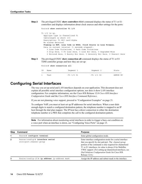
The privileged EXEC show controllers t1/e1 comm<strong>and</strong> displays the status of <strong>T1</strong> or <strong>E1</strong><br />
controllers <strong>and</strong> displays information about clock sources <strong>and</strong> other settings for the ports:<br />
Router# show controller <strong>T1</strong> 1/0<br />
<strong>T1</strong> 1/0 is up.<br />
Applique type is Channelized <strong>T1</strong><br />
Cablelength is short 133<br />
Description: <strong>T1</strong> WIC card Alpha<br />
No alarms detected.<br />
Framing is ESF, Line Code is B8ZS, Clock Source is Line Primary.<br />
Data in current interval (1 seconds elapsed):<br />
0 Line Code Violations, 0 Path Code Violations<br />
0 Slip Secs, 0 Fr Loss Secs, 0 Line Err Secs, 0 Degraded Mins<br />
0 Errored Secs, 0 Bursty Err Secs, 0 Severely Err Secs, 0 Unavail Secs<br />
Step 3<br />
The privileged EXEC show connection all comm<strong>and</strong> displays the status of <strong>T1</strong> or <strong>E1</strong><br />
TDM controller groups <strong>and</strong> how they are set up:<br />
Router# show connection all<br />
ID Name Segment 1 Segment 2 State<br />
========================================================================<br />
1 Test -<strong>T1</strong> 1/0 01 -<strong>T1</strong> 1/1 02 ADMIN UP<br />
<strong>Configuring</strong> Serial Interfaces<br />
The way you set up serial <strong>and</strong> LAN interfaces depends on your application. This document does not<br />
explain all possible serial interface configuration options, nor does it show LAN interface<br />
configuration. For complete information, see the Cisco IOS Release 12.0 Cisco IOS Interface<br />
Configuration Guide <strong>and</strong> the Cisco IOS Interface Comm<strong>and</strong> Reference.<br />
If you are not planning voice support, proceed to “Configuration Examples” on page 21.<br />
To configure VoIP, you must at least set up IP addresses for serial interfaces. When a user dials<br />
enough digits to match a configured destination pattern, the telephone number is mapped to an IP<br />
host through the dial plan mapper. The IP host has a direct connection to either the destination<br />
telephone number or a PBX that completes the call to the configured destination pattern.<br />
Note For information about monitoring serial interfaces in order to trigger a busy-out condition on<br />
a voice port when an interface is down, see “<strong>Configuring</strong> <strong>Voice</strong> <strong>Port</strong>s” on page 15.<br />
Step Comm<strong>and</strong> Purpose<br />
1 Router# configure terminal Enter global configuration mode.<br />
2 Router(config)# interface serial<br />
slot/port:channel-group<br />
Enter interface configuration mode for a serial interface<br />
that you specify by slot <strong>and</strong> port. The :channel-group<br />
portion of the comm<strong>and</strong> is only required for channelized<br />
<strong>T1</strong> or <strong>E1</strong> interfaces; its value is always 0 for <strong>Multiflex</strong><br />
VWIC support. (For setting up channelized interfaces, see<br />
Dial Solutions Configuration Guide for Cisco IOS<br />
Release 12.0.)<br />
3 Router(config-if)# ip address ip-address mask Assign the IP address <strong>and</strong> subnet mask to the interface.<br />
14 Cisco IOS Release 12.0(7)T