Configuring 1- and 2-Port T1/E1 Multiflex Voice/WAN ... - docs.mind.ru
Configuring 1- and 2-Port T1/E1 Multiflex Voice/WAN ... - docs.mind.ru
Configuring 1- and 2-Port T1/E1 Multiflex Voice/WAN ... - docs.mind.ru

Create successful ePaper yourself
Turn your PDF publications into a flip-book with our unique Google optimized e-Paper software.
Configuration Examples<br />
Additional Considerations<br />
Here are some additional key points for consideration:<br />
• The tdm-group 2 timeslots 13-24 type e&m comm<strong>and</strong> defines Drop <strong>and</strong> Insert by setting up the<br />
timeslots from each <strong>T1</strong> that will be used in the digital cross-connect. The type keyword is<br />
optional, but its use is specific to the Drop <strong>and</strong> Insert feature.<br />
— If you include the type keyword with a signaling type, the Drop-<strong>and</strong>-Insert cross-connect<br />
ensures that the specified signaling (on-hook <strong>and</strong> off-hook) is passed between the DS0s. It<br />
also uses the signaling bits to signal busy-out if one of the <strong>T1</strong>s goes down.<br />
— If you do not use the type keyword, the Drop-<strong>and</strong>-Insert cross-connect is clear channel <strong>and</strong><br />
does not interpret any signaling.<br />
• The connect tdm1 <strong>T1</strong> 1/0 2 <strong>T1</strong> 1/1 3 comm<strong>and</strong> activates the Drop-<strong>and</strong>-Insert digital<br />
cross-connect between the <strong>T1</strong>s. The tdm1 portion of the comm<strong>and</strong> is just a name for the<br />
cross-connect, <strong>and</strong> the name can be any word, number, or series of letters.<br />
• You can verify Drop-<strong>and</strong>-Insert connections by using the show connection comm<strong>and</strong>.<br />
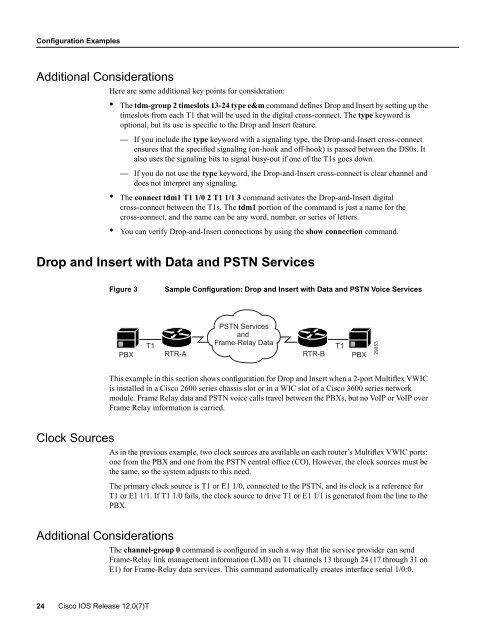
Drop <strong>and</strong> Insert with Data <strong>and</strong> PSTN Services<br />
Figure 3<br />
Sample Configuration: Drop <strong>and</strong> Insert with Data <strong>and</strong> PSTN <strong>Voice</strong> Services<br />
PBX<br />
<strong>T1</strong><br />
RTR-A<br />
PSTN Services<br />
<strong>and</strong><br />
Frame-Relay Data<br />
RTR-B<br />
<strong>T1</strong><br />
PBX<br />
29053<br />
This example in this section shows configuration for Drop <strong>and</strong> Insert when a 2-port <strong>Multiflex</strong> VWIC<br />
is installed in a Cisco 2600 series chassis slot or in a WIC slot of a Cisco 3600 series network<br />
module. Frame Relay data <strong>and</strong> PSTN voice calls travel between the PBXs, but no VoIP or VoIP over<br />
Frame Relay information is carried.<br />
Clock Sources<br />
As in the previous example, two clock sources are available on each router’s <strong>Multiflex</strong> VWIC ports:<br />
one from the PBX <strong>and</strong> one from the PSTN central office (CO). However, the clock sources must be<br />
the same, so the system adjusts to this need.<br />
The primary clock source is <strong>T1</strong> or <strong>E1</strong> 1/0, connected to the PSTN, <strong>and</strong> its clock is a reference for<br />
<strong>T1</strong> or <strong>E1</strong> 1/1. If <strong>T1</strong> 1/0 fails, the clock source to drive <strong>T1</strong> or <strong>E1</strong> 1/1 is generated from the line to the<br />
PBX.<br />
Additional Considerations<br />
The channel-group 0 comm<strong>and</strong> is configured in such a way that the service provider can send<br />
Frame-Relay link management information (LMI) on <strong>T1</strong> channels 13 through 24 (17 through 31 on<br />
<strong>E1</strong>) for Frame-Relay data services. This comm<strong>and</strong> automatically creates interface serial 1/0:0.<br />
24 Cisco IOS Release 12.0(7)T