NX W R e v ersible Chiller Installation Manual - WaterFurnace
NX W R e v ersible Chiller Installation Manual - WaterFurnace
NX W R e v ersible Chiller Installation Manual - WaterFurnace

Create successful ePaper yourself
Turn your PDF publications into a flip-book with our unique Google optimized e-Paper software.
<strong>NX</strong>W REVERSIBLE CHILLER INSTALLATION MANUAL<br />
Inputs and Outputs Configuration<br />
DUAL STAGE WW<br />
Input Name Input Output Name Output<br />
Entering Load Water Temperature AI 1 Compressor 1 DO1<br />
Leaving Load Water Temperature 1 AI 2 Compressor 2 DO2<br />
Source Heating Freeze Detection 1 AI 3 Reversing Valve DO3<br />
Source Heating Freeze Detection 2 AI 4 Accessory DO4<br />
Load Cooling Freeze Detection 1 AI 5 Compressor 1 Alarm DO5<br />
Load Cooling Freeze Detection 2 AI 6 Compressor 2 Alarm DO6<br />
Network Output<br />
DO7<br />
Load Flow Proving Switch DI 1 Network Output DO8<br />
Emergency Shutdown DI 2 Network Output D09<br />
Stage 2 Low Pressure DI 3<br />
Source Htg Freeze Detection Select - 30ºF DI 4 Future PWM1<br />
Load Htg Freeze Detection Select - 30ºF DI 5 Future PWM2<br />
Stage 1 Low Pressure DI 6<br />
Thermostat Y1 DI 7<br />
Thermostat Y2 DI 8<br />
Thermostat B DI 9<br />
Source Flow Proving Switch<br />
D10<br />
Stage 1 High Pressure<br />
DI11<br />
Stage 2 High Pressure<br />
DI12<br />
XP10 Expansion Card<br />
Input Name Input Output Name Output<br />
Entering Source Water Temperature AI 1 Unused DO 1<br />
Leaving Source Water Temperature 1 AI 2 Unused DO 2<br />
Current Switch 1 - Compressor 1 AI 3 Unused DO 3<br />
Current Switch 2 - Compressor 2 AI 4 Unused DO 4<br />
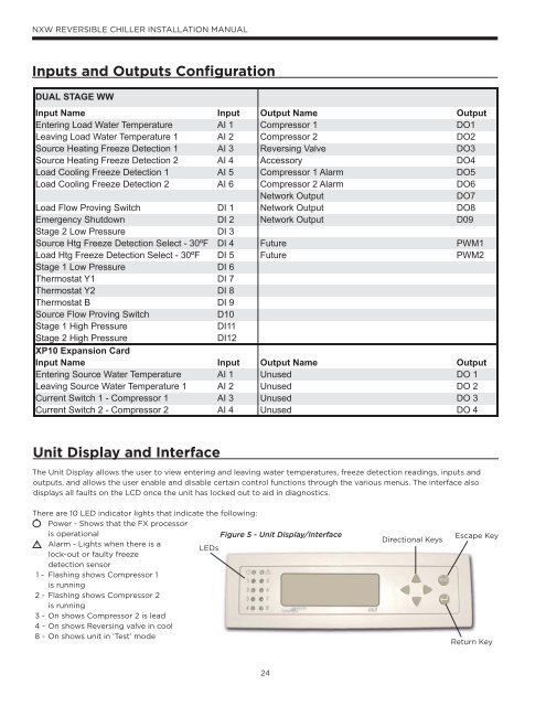
Unit Display and Interface<br />
The Unit Display allows the user to view entering and leaving water temperatures, freeze detection readings, inputs and<br />
outputs, and allows the user enable and disable certain control functions through the various menus. The interface also<br />
displays all faults on the LCD once the unit has locked out to aid in diagnostics.<br />
There are 10 LED indicator lights that indicate the following:<br />
Power - Shows that the FX processor<br />
is operational<br />
Figure 5 - Unit Display/Interface<br />
! Alarm - Lights when there is a<br />
LEDs<br />
lock-out or faulty freeze<br />
detection sensor<br />
1 - Flashing shows Compressor 1<br />
is running<br />
2 - Flashing shows Compressor 2<br />
is running<br />
3 - On shows Compressor 2 is lead<br />
4 - On shows Reversing valve in cool<br />
8 - On shows unit in ‘Test’ mode<br />
Directional Keys<br />
Escape Key<br />
Return Key<br />
24