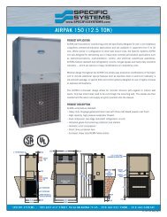
AIRPAK 150 (12.5 TON) - Specific Systems
AIRPAK 150 (12.5 TON) - Specific Systems
AIRPAK 150 (12.5 TON) - Specific Systems

You also want an ePaper? Increase the reach of your titles
YUMPU automatically turns print PDFs into web optimized ePapers that Google loves.
<strong>AIRPAK</strong> <strong>150</strong> (<strong>12.5</strong> <strong>TON</strong>)<br />
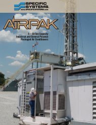
PRODUCT APPLICATION<br />
AirPAK wall-mounted air conditioning units are specifically designed for use in<br />
non-hazardous (classified) commercial/industrial applications and are available<br />
in capacities from 5 to 20 tons. While similar in configuration to other wallmount<br />
units, the <strong>Specific</strong> <strong>Systems</strong> AirPAK line was designed for demanding use<br />
in heavy-duty commercial/industrial applications such as telecommunications,<br />
instrumentation, control, and electrical powerhouse assemblies. AirPAKs feature<br />
standard dual refrigeration circuits, hot-gas bypass and heavy duty industrial<br />
cabinetry — which are options or heavy modifications on competitive units.<br />
Modular design throughout the AirPAK line allows easy production modifications<br />
of the basic unit to include additional special features such as stainless steel<br />
or aluminum cabinetry, a low ambient package, or special filter and control<br />
systems designed for use in highly corrosive or explosive atmospheres.<br />
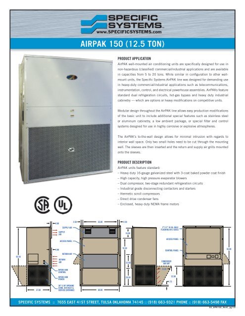
The AirPAK’s to-the-wall design allows for minimal intrusion with regards to<br />
interior wall space. Only two small holes need to be cut through the mounting<br />
wall. The sleeves are then inserted and the return and supply air grills mounted<br />
onto the sleeves.<br />
PRODUCT DESCRIPTION<br />
AirPAK units feature standard:<br />
– Heavy duty 16-gauge galvanized steel with 3-coat baked powder coat finish<br />
– High capacity, high pressure evaporator blowers<br />
– Dual compressor, two-stage redundant refrigeration circuits<br />
– Industrial grade disconnecting contactors and starters<br />
– Hermetic scroll compressors<br />
– Direct drive condenser fans<br />
– Enclosed, heavy duty NEMA frame motors<br />
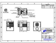
2.00<br />
SUPPLY<br />
AIR<br />
SUPPLY AIR<br />
ACCESS PANEL<br />
2.50 55.00<br />
2.50<br />
16.00<br />
2" X 2" 16 GA. GALV.<br />
FLASHING ON 3 SIDES<br />
ACCESS PANEL<br />
93.50<br />
2.00<br />
RETURN AIR<br />
RETURN<br />
AIR<br />
76.50<br />
22.00<br />
CONTROL PANEL<br />
CONDENSER<br />
AIR OUT<br />
94.00<br />
MYERS HUB<br />
CONTROL<br />
24.00<br />
MYERS HUB<br />
POWER<br />
28.50<br />
1.75<br />
32.00<br />
37.88<br />
30" X 30" OPENING<br />
COND. AIR INLET &<br />
SERVICE ENTRANCE<br />
60.00<br />
SPECIFIC SYSTEMS :: 7655 EAST 41ST STREET, TULSA OKLAHOMA 74145 :: (918) 663-9321 PHONE :: (918) 663-5498 FAX<br />
SS_APK<strong>150</strong>_RevC_pg1/3
<strong>AIRPAK</strong> <strong>150</strong> (<strong>12.5</strong> <strong>TON</strong>)<br />
STANDARD PRODUCT SPECIFICATIONS<br />
<strong>Specific</strong> <strong>Systems</strong> will furnish a <strong>Specific</strong> <strong>Systems</strong> AirPAK Model <strong>150</strong> unit. Total cooling capacity<br />
of the unit shall be not less than <strong>150</strong>,000 BTU per hour, with 4250 cfm of 80° dry bulb / 67°<br />
wet bulb temperature air entering the evaporator coil. Total airflow capacity of the system<br />
shall be not less than 4400 cfm with a total external static pressure of 1.0 in. w.c.<br />
Supply air blower in the unit shall be two spark-proof horizontally-mounted backwardlyinclined<br />
fan and motor combinations packaged in a 16-gauge hot-dipped galvanized<br />
assembly. The assembly shall be designed to produce 4400 cfm at 1.0" static pressure and<br />
shall be driven by two 1.20 horsepower, 1650 rpm TEFC motors designed to operate in a<br />
non-hazardous (classified) environment.<br />
All controls, contactors, and overload protection for fan motors, compressors, heaters, etc.,<br />
shall be an integral part of the unit.<br />
The unit cabinet shall have 48" width, 96" height, 28" depth. Standard unit cabinet shall be<br />
constructed of 16-gauge hot-dipped galvanized steel that has been powder coated. Powder<br />
coat shall be a TGIC polyester powder coat with a minimum of 4 mils thickness, heat cured<br />
at 375°F, providing a superior coating to corrosion, impact, and abrasion protection when<br />
compared to solvent paint. The unit cabinet shall be internally acoustically insulated with<br />
1.0" closed cell Armaflex and provided with stainless steel access fasteners on removable<br />
doors.<br />
Evaporator section of the unit shall be constructed of 16-gauge hot-dipped galvanized steel<br />
with a cooling coil constructed of aluminum fins mechanically joined to seamless copper<br />
tubing. The evaporator coil shall be dual-circuited with two separated refrigerant circuits.<br />
Each circuit shall be equipped with service valves, a sight glass, moisture indicator, and<br />
fully-adjustable expansion valves. A full-area stainless steel drain pan with auxiliary<br />
overflow shall be provided.<br />
Compressor/condenser section shall be constructed of hot-dipped galvanized steel with two<br />
7.5 ton compressors and two 7.5 ton condenser circuits complete with service valves on<br />
each circuit. The condenser coil is to be constructed of aluminum fins mechanically joined to<br />
seamless copper tubing. Condenser fan shall produce 7200 cfm total and shall be driven by<br />
a 2 horsepower, 1160 rpm TEFC motor designed to operate in a non-hazardous (classified)<br />
environment.<br />
The unit shall be equipped with a unitized control system with the following features: Unit<br />
shall have two-stage cooling (and heating, if option is purchased) control with ± 0.25°F<br />
accuracy, 65°F – 95°F set point, three-point system fan switch (fan only, heat/cool cycle<br />
operation, and continuous fan cooling) and a control Power-On indicator lamp. System<br />
control thermostat shall have a digital readout of the system status, a power on/off switch,<br />
and remote/local control status indicating lamps.<br />
The cooling system shall have high and low refrigerant pressure overloads, condenser and<br />
evaporator fan overloads with automatic reset on all overload conditions, electric heat,<br />
high temperature overload, compressor overloads, compressor short time delays, defrost<br />
cycle with control system defrost, and refrigeration system failure lights with Form C alarm<br />
contacts.<br />
The entire unit shall be designed and constructed with all major system assemblies<br />
designed in utilized assemblies that may be easily and quickly repaired by service personnel<br />
with minimum down time in the operation of the system.<br />
AVAILABLE OPTIONS<br />
Please contact <strong>Specific</strong> <strong>Systems</strong> about other available options.<br />
– Remote Control – Low Ambient Controls<br />
– Multiplexor (up to 5 units) – Economizer<br />
– Corrosion-resistant coated coils – Humidistat<br />
– Carboline coating, components – HEPA filter<br />
– Unit-mounted disconnect – Field start-up/commission<br />
AVAILABLE COLORS<br />
WHITE LIGHT GREY DARK GREY DESERT TAN<br />
SPECIFIC SYSTEMS :: 7655 EAST 41ST STREET, TULSA OKLAHOMA 74145 :: (918) 663-9321 PHONE :: (918) 663-5498 FAX<br />
SS_APK<strong>150</strong>_RevB_pg2/3
<strong>AIRPAK</strong> <strong>150</strong> (<strong>12.5</strong> <strong>TON</strong>)<br />
Electrical <strong>Specific</strong>ations for Standard Units<br />
Electric Power 460/480<br />
3Φ–60Hz<br />
230/240<br />
3Φ–60Hz<br />
415V<br />
3Φ–50Hz<br />
380V<br />
3Φ-50Hz<br />
200V<br />
3Φ–50Hz<br />
*LRA – Lock Rotor Amps. Defined as evaporator fan, condenser fan, and compressor operating at full load and one compressor at Lock Rotor Amps.<br />
575V<br />
3Φ–60Hz<br />
Evaporator Fan Motor FLA 2.0 (4.0) 4.0 (8.0) 1.9 (3.8) 2.1 (4.2) 4.8 (9.6) 1.6 (3.2)<br />
Condensor Motor FLA 3.5 7.0 3.4 3.7 8.4 2.8<br />
Compressor Motor LRA 15.7 (31.4) 31.4 (62.8) 15.1 (30.2) 16.5 (33.0) 37.7 (75.4) 12.6 (25.2)<br />
Heat 20KW, Amps (Actual KW) 26.0 (21.6) 53.2 (21.2) 29.8 (21.4) 29.7 (19.5) 55.0 (19.1) 23.3 (23.2)<br />
Heat 15KW, Amps (Actual KW) 18.5 (15.4) 37.7 (15.0) 22.4 (16.1) 20.6 (13.5) 39.5 (13.7) 15.6 (15.5)<br />
Heat 10KW, Amps (Actual KW) 13.0 (10.8) 26.6 (10.6) 16.0 (11.5) 14.7 (9.6) 23.1 (8.0) —<br />
Total Cooling FLA 38.9 77.8 37.4 40.9 93.4 21.7<br />
10–20 KW Heat<br />
MCA 42.8 85.7 41.2 45.0 102.8 33.1<br />
MOP 58.2 117.1 56.3 61.5 140.5 47.0<br />
Unit LRA* 117 235 113 123 282 61<br />
Operating Range 216V–253V 180V–220V 432V–506V 216V–253V 373V–456V 517V–600V<br />
Actual Capacity @ 60 Hz, 80° DB / 67° WB Entering Evaporator Coil<br />
Ambient Condition Sensible Capacity Total Capacity<br />
75°F (24°C) 123,058 BTUH 185,162 BTUH<br />
85°F (29°C) 119,484 BTUH 178,630 BTUH<br />
95°F (35°C) 114,934 BTUH 169,660 BTUH<br />
110°F (43°C) 109,656 BTUH 155,860 BTUH<br />
120°F (49°C) 104,910 BTUH 145,352 BTUH<br />
CFM @ ESP (Wet Coil, 60Hz)<br />
Unit Dimensions<br />
0.10 0.20 0.30<br />
Filter Size (#) Width Depth Height Weight<br />
5200 5000 4825 24 × 20 × 2 (1) 48" 28" 94" 1100 lbs<br />
20 × 20 × 2 (1)<br />
SPECIFIC SYSTEMS :: 7655 EAST 41ST STREET, TULSA OKLAHOMA 74145 :: (918) 663-9321 PHONE :: (918) 663-5498 FAX<br />
SS_APK<strong>150</strong>_RevB_pg3/3