Prosonic Flow 92F - å¾·å½Endress+Hauser(E+Hå ¬å¸)
Prosonic Flow 92F - å¾·å½Endress+Hauser(E+Hå ¬å¸)
Prosonic Flow 92F - å¾·å½Endress+Hauser(E+Hå ¬å¸)

You also want an ePaper? Increase the reach of your titles
YUMPU automatically turns print PDFs into web optimized ePapers that Google loves.
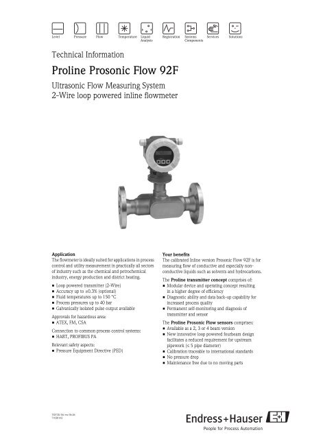
Technical Information<br />
Proline <strong>Prosonic</strong> <strong>Flow</strong> <strong>92F</strong><br />
Ultrasonic <strong>Flow</strong> Measuring System<br />
2-Wire loop powered inline flowmeter<br />
Application<br />
The flowmeter is ideally suited for applications in process<br />
control and utility measurement in practically all sectors<br />
of industry such as the chemical and petrochemical<br />
industry, energy production and district heating.<br />
• Loop powered transmitter (2-Wire)<br />
• Accuracy up to ±0.3% (optional)<br />
• Fluid temperatures up to 150 °C<br />
• Process pressures up to 40 bar<br />
• Galvanically isolated pulse output available<br />
Approvals for hazardous area:<br />
• ATEX, FM, CSA<br />
Connection to common process control systems:<br />
•HART, PROFIBUS PA<br />
Relevant safety aspects:<br />
• Pressure Equipment Directive (PED)<br />
Your benefits<br />
The calibrated Inline version <strong>Prosonic</strong> <strong>Flow</strong> <strong>92F</strong> is for<br />
measuring flow of conductive and especially nonconductive<br />
liquids such as solvents and hydrocarbons.<br />
The Proline transmitter concept comprises of:<br />
• Modular device and operating concept resulting<br />
in a higher degree of efficiency<br />
• Diagnostic ability and data back-up capability for<br />
increased process quality<br />
• Permanent self-monitoring and diagnosis of<br />
transmitter and sensor<br />
The Proline <strong>Prosonic</strong> <strong>Flow</strong> sensors comprises:<br />
• Available as a 2, 3 or 4 beam version<br />
• New innovative loop powered fourbeam design<br />
facilitates a reduced requirement for upstream<br />
pipework (≤ 5 pipe diameter)<br />
• Calibration traceable to international standards<br />
• No pressure drop<br />
• Maintenance free due to no moving parts<br />
TI073D/06/en/06.06<br />
71028162
Proline <strong>Prosonic</strong> <strong>Flow</strong> <strong>92F</strong><br />
Function and system design<br />
Measuring principle<br />
A <strong>Prosonic</strong> <strong>Flow</strong> inline flowmeter measures the flow rate of the passing fluid by using sensor pairs located on<br />
opposite sides of the meter body and at an angle so that one of the sensors in the pair is slightly downstream.<br />
The flow signal is established by alternating an acoustic signal between the sensor pairs and measuring the time<br />
of flight of each transmission. Then utilizing the fact that sound travels faster with the flow versus against the<br />
flow, this differential time (∆ T) can be used to determine the fluids velocity between the sensors.<br />
The volume flow rate is established by combining all the flow velocities determined by the sensor pairs with<br />
the cross sectional area of the meter body and extensive knowledge about fluid flow dynamics. The design of<br />
the sensors and their position ensures that only a short straight run of pipe upstream of the meter is required<br />
after typical flow obstructions such as bends in one or two planes. Advance digital signal processing facilitates<br />
constant validation of the flow measurement reducing susceptibility to multiphase flow conditions and<br />
increases the reliability of the measurement.<br />
T'<br />
1<br />
T 1<br />
T<br />
<br />
e<br />
a0006215<br />
Measuring system<br />
The measuring system consists of a transmitter and a sensor. Two versions are available:<br />
• Compact version: transmitter and sensor form a mechanical unit<br />
• Remote version: transmitter and sensor are mounted physically separate from one another<br />
Transmitter<br />
<strong>Prosonic</strong> <strong>Flow</strong> 92<br />
<strong>Prosonic</strong> <strong>Flow</strong> 92 remote version<br />
• Two line liquid crystal display<br />
• Operation with push buttons (only HART<br />
version)<br />
• 2-Wire loop powered<br />
• Optional explosion proof housing<br />
a0005962<br />
a0005963<br />
Sensor<br />
F<br />
a0005966<br />
F (remote Version)<br />
• Universal sensor for fluid temperatures up<br />
to 150°C<br />
• Nominal diameters DN 25 to 150, 1"…6"<br />
• Tube material: stainless steel<br />
• Process pressures up to 40 bar<br />
Remote version:<br />
• Optional IP68 housing<br />
• Standard remote cable length of 10 and<br />
30 meters<br />
• Optional remote cable length made to<br />
order up to a maximum 50 meters<br />
a0005967<br />
Endress+Hauser 3
Proline <strong>Prosonic</strong> <strong>Flow</strong> <strong>92F</strong><br />
Input<br />
Measured variable<br />
Measuring range<br />
<strong>Flow</strong> velocity (transit time difference proportional to flow velocity)<br />
Typically v = –10 to 10 m/s with the specified accuracy<br />
Nominal diameters<br />
Range for full scale values (liquids) m min(F) to m max(F)<br />
25 0 to 300 dm 3 /min<br />
40 0 to 700 dm 3 /min<br />
50 0 to 1100 dm 3 /min<br />
80 0 to 3000 dm 3 /min<br />
100 0 to 4700 dm 3 /min<br />
150 0 to 600 m 3 /h<br />
Output<br />
Outputs in general<br />
The following measured variables can generally be output via the outputs:<br />
Current output Freq. output Pulse output Status output<br />
Volume flow X X X Limit value<br />
Sound velocity X X – Limit value<br />
<strong>Flow</strong> velocity X X – Limit value<br />
Signal strength X X – Limit value<br />
Output signal<br />
Current output:<br />
Current output:<br />
• 4 to 20 mA with HART<br />
• Full scale value and time constant (0 to 100 s) can be set<br />
Pulse/status output/Frequency output:<br />
Open collector, passive, galvanically isolated<br />
• Non-Ex, Ex d - version:<br />
Umax = 35 V, with 15 mA current limiting, Ri = 500<br />
• Ex i version:<br />
Umax = 30 V, with 15 mA current limiting, Ri = 500<br />
The pulse/status output can be configured as:<br />
• Pulse output:<br />
– Pulse value and pulse polarity can be selected,<br />
– Pulse width can be configured (0.005 to 2s)<br />
– Pulse frequency max. 100 Hz<br />
• Status output:<br />
Can be configured for diagnosis code messages or flow limit values<br />
• Frequency output:<br />
End frequency 0 to 1000 Hz (fmax = 1250 Hz)<br />
4 Endress+Hauser
Proline <strong>Prosonic</strong> <strong>Flow</strong> <strong>92F</strong><br />
PROFIBUS PA interface<br />
• PROFIBUS PA in accordance with IEC 61158 (MBP), galvanically isolated<br />
• Profile Version 3.01<br />
• Data transmission rate: 31.25 kBaud<br />
• Current consumption: 16 mA<br />
• Permitted supply voltage: 9 to 32 V; 0.5 W<br />
• Bus connection with integrated reverse polarity protection<br />
• Error current FDE (Fault Disconnection Electronic): 0 mA<br />
• Signal coding: Manchester II<br />
• Bus address can be configured via miniature switches at the device or operating program<br />
Signal on alarm<br />
Current output:<br />
Failsafe mode selectable (e.g. in accordance with NAMUR Recommendation NE 43)<br />
Status output:<br />
“Non conductive” in the event of fault or power supply failure.<br />
Load<br />
R<br />
[ ] R [ ]<br />
W B<br />
W B<br />
R<br />
[ ]<br />
W B<br />
1100 1100<br />
1000 1000<br />
900 900<br />
800 800<br />
Ex<br />
700 700<br />
Ex d<br />
600 600<br />
500 500<br />
400 400<br />
300 300<br />
200 200<br />
100 100<br />
0 0<br />
10 15 20 25 30 36 10 15 20 25 30 36<br />
18 21<br />
1100<br />
1000<br />
900<br />
800<br />
700<br />
600<br />
500<br />
400<br />
300<br />
200<br />
100<br />
0<br />
Ex i und Ex iEx n<br />
10 15 20 25 30<br />
18<br />
U<br />
[ ]<br />
S V<br />
Behavior of load and supply voltage<br />
The area marked in gray indicates the permissible load (with HART: min. 250 .)<br />
The load is calculated as follows:<br />
R B<br />
= (U S–U Kl)<br />
= (U S–U Kl)<br />
-3<br />
(I –10 ) 0.022<br />
max<br />
a0001921<br />
R B<br />
U S<br />
U KL<br />
I max.<br />
Load, load resistance<br />
Supply voltage:<br />
- Non-Ex = 12 to 35 V DC<br />
- Ex d = 15 to 35 V DC<br />
- Ex i = 12 to 30 V DC<br />
Terminal voltage:<br />
- Non-Ex = min. 12 V DC<br />
- Ex d = min. 15 V DC<br />
- Ex i = min. 12 V DC<br />
Output current (22.6 mA)<br />
Low flow cutoff<br />
Galvanic isolation<br />
Switch points for low flow cutoff can be selected as required.<br />
All circuits for inputs, outputs, and power supply are galvanically isolated from each other.<br />
Endress+Hauser 5