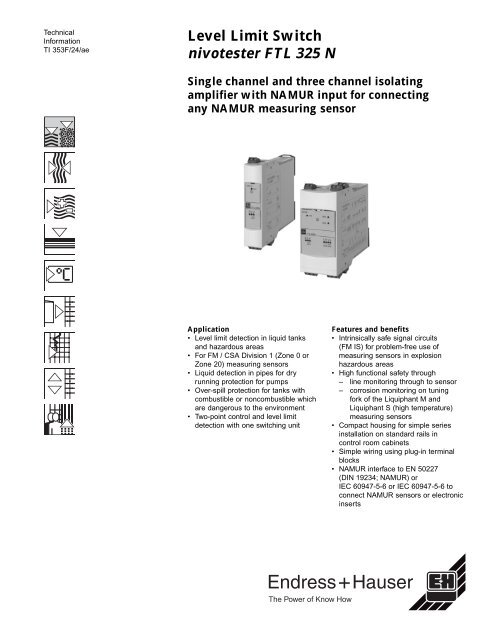
Level Limit Switch nivotester FTL 325 N - å¾·å½Endress+Hauser(E+H ...
Level Limit Switch nivotester FTL 325 N - å¾·å½Endress+Hauser(E+H ...
Level Limit Switch nivotester FTL 325 N - å¾·å½Endress+Hauser(E+H ...
- No tags were found...
Create successful ePaper yourself
Turn your PDF publications into a flip-book with our unique Google optimized e-Paper software.
Nivotester <strong>FTL</strong> <strong>325</strong> N2. When channels two and three are used for two-point control ∆s, the measuringdevice consists of:• Two measuring sensors• Three channel Nivotester• Control or signal devicesHazardous Area(IS)Non-hazardous Area<strong>FTL</strong> <strong>325</strong> N-#3#3CH 3CH 2∆ s3. When channels two and three are used for two-point control ∆s, and channel onefor overspill protection, the measuring device consists of:• Three measuring sensors• Three channel Nivotester• Control or signal devicesHazardous Area(IS)Non-hazardous Area<strong>FTL</strong> <strong>325</strong> N-#3#3CH 3CH 2∆ sCH 14. When channel two is used for measuring the level limit with two level limit relaysand channel one is used for measuring other level limits, the measuring deviceconsists of:• Two measuring sensors• Three channel Nivotester• Control or signal devicesHazardous Area(IS)Non-hazardous AreaCH 3<strong>FTL</strong> <strong>325</strong> N-#3#3CH 2CH 1Endress+Hauser5
Nivotester <strong>FTL</strong> <strong>325</strong> N5. When channel two is used for measuring the level limit with two level limit relays,the measuring device consists of:• One measuring sensor• Three channel Nivotester• Control or signal devicesHazardous Area(IS)Non-hazardous AreaCH 3<strong>FTL</strong> <strong>325</strong> N-#3#3CH 2NOTE: Since channel one is not used, the alarm must be switched to “OFF”.Input parametersMeasured variableMeasuring rangeInput signalThe limit signal can be triggered at minium or maximum height as required.The measuring range is dependent on the installation location of the sensors.• Input for <strong>FTL</strong> <strong>325</strong>N: galvanically isolated from power supply and output.• Protection type: FM Intrinsically Safe, Class I, II, III; Division 1, Groups A-G.CSA Intrinsically Safe, Class I, II, III; Division 1, Groups A-G.• Connectable measuring sensors:- Liquiphant M <strong>FTL</strong> 50/51, <strong>FTL</strong> 50 H/51 H, <strong>FTL</strong> 51 C with electronic insertFEL 56 or FEL 58.- Liquiphant S (HT) <strong>FTL</strong> 70/71 with electronic insert FEL 56 or FEL 58.- Any number of sensors specified to EN 50227 (DIN 19234; NAMUR) orIEC 60947-5-6.- Contact switches with appropriate resistance circuit.• Measuring sensor power supply: from <strong>FTL</strong> <strong>325</strong> N Nivotester.• Connecting line: two-wire, shielding not required.• Line resistance: maximum 25 Ω per wire.• Signal transmission: current signal on power supply line.• Control current range: < 1.2 mA / > 2.1 mA.• Line interruption monitoring: < 200 µA and short-circuit > 6.1 mA (can be switchedoff).Further details for installing measuring sensors outside explosion hazardous zonescan be found in the appropriate certificates.Output parametersOutput signal6• Relay output per channel: one potential-free relay contact for the level alarm.• De-energized current safety circuit: the function of the de-energized current safetycircuit is dependent on the setting made on the electronic insert FEL 56 or 58sensors and on selection of the error current signal on the Nivotester.• <strong>Switch</strong> delay: approximately 0.5 seconds.• <strong>Switch</strong>ing power of the relay contacts:AC versionV ~ maximum 253 VI ~ maximum 2 AP ~ maximum 500 VA at cos ϕ >= 0.7 (power factor)DC versionV = maximum 40 VI = maximum 2 AP = maximum 80 W• Life: at least 10 5 switching operations at maximum contact load.• Function displays: LEDs for operation, level alarm and fault.Endress+Hauser
Nivotester <strong>FTL</strong> <strong>325</strong> NFault signalGalvanic isolationRelay de-energized, fault is indicated by red LEDsAll input and output channels and relay contacts are galvanically isolated from eachother.Power supplyElectrical connectionTerminal blocksThe removable terminal blocks are separated into intrinsically safe connections (at thetop of the unit) and non-intrinsically safe connections (at the bottom of the unit).Terminal blocks are different colors to easily distinguish between the two types. Blueblocks are for the intrinsically safe section and grey for the non-intrinsically safeblocks. This ensures safety when wiring unit.Connecting the measuring sensor(the upper, blue terminal blocks)The two-wire connecting line between the Nivotester and the Liquiphant, Nivopuls orSoliphant measuring sensor can either be a commercially available installation cableor wires in a multi-wire cable for instrumentation purposes. Line resistance may be amaximum of 25 Ω per wire. If strong eletromagnetic interference is expected, e.g.from machines or radio devices, a shielded cable must be used. Only connect theshield to the ground connection, and not to the Nivotester.Using the measuring system in explosion hazardous areasPlease observe all local codes and regulations on explosion protectionconcerning the type and installation of intrinsically safe signal wiring. Pleaserefer to the Safety Instruction XA 134F for maximum permissible values ofcapacitance and inductance.Connecting signal and control devices(the lower, grey terminal blocks)The relay function is dependent on the level and fail-safe circuit. If an instrument isconnected at high inductance (e.g. contactor, solenoid valve, etc.), a spark suppressormust be installed to protect the relay contact.Connecting the supply voltage(the lower, grey terminal blocks)For voltage variations, refer to the Ordering Information section. A fuse is built intothe power supply current circuit. This eliminates the need to connect a fine-wire fusein series. The Nivotester is equipped with reverse polarity protection.Power supplyPower consumptionSetting time/lengthAC version:• 85 to 253 VAC, 50/60 HzDC version:• 20 to 60 VDC• DC supply, maximum 60 mA (one channel unit)• DC supply, maximum 115 mA (three channel unit)• Permissible residual ripple witin tolerance: V pp= maximum 2 VAC version:• 1.75 W maximum (one channel unit)• 2.25 W maximum (three channel unit)DC version:• 1.2 W maximum, at V min20 V (one channel unit)• 2.25 W maximum, at V min20 V (threee channel unit)Final switching status after switching on the power supply, approximately 10 to 20seconds, depending on the connected measuringEndress+Hauser7
TNivotester <strong>FTL</strong> <strong>325</strong> NOperating conditions, installationInstallation guidelinesOperating locationThe Nivotester must be housed in a cabinet outside the explosion hazardous area. Aprotective housing, NEMA 4 (IP 65) is available which can house up to four singlechannel units or two three channel units for outdoor installation.NOTE:Select a mounting location which proctects the units from weather and impacts. Donot install in direct sunlight, especially in warm climates.HazardousArea (IS)Non-hazardousAreaNAMURISCircuitMinimumNEMA 4(IP 65)<strong>FTL</strong> <strong>325</strong> NInput powerCH 1CH 2CH 3Installation positionMount the unit vetical on a DIN top-hat rail.[Ex ia]CH1CH2EN 50022; 35 x 7.5EN 50022; 35 x 15CH3<strong>FTL</strong> <strong>325</strong>CH1CH2 CH3Top-hat rail<strong>FTL</strong> <strong>325</strong> units fit two DINrail units, depths of 0.30" (7.5 mm)or 0.60" (15 mm)Operating conditions, ambientAmbient temperatureClimatic classIngress protectionElectromagnetic compatibility (EMC)Single installation: -4° to +140°F (-20° to +60°C)Rail mounting, without gaps: -4° to +122°F (-20° to +50°C)Storage temperature: -4° to +140°F, preferably at 68°F (-20° to +60°C, preferably+20°C)Installation in protective housing: -4° to +104°F (-20° to + 40°C)3K3 and 3M2, according to EN 60721-3-3NEMA 1 (IP 20)Interference emission to EN 61326, Class B apparatusInterference emission to EN 61326, Appendix A (industry) and NAMURRecommendation NE 21 (EMC)8Endress+Hauser
Nivotester <strong>FTL</strong> <strong>325</strong> NMechanical constructionDimensionsMounting distancesAll dimensions are in inches (mm)Non-hazardousAreaHazardousArea(IS)<strong>FTL</strong> <strong>325</strong>- ..3<strong>FTL</strong> <strong>325</strong>- ..1<strong>FTL</strong> <strong>325</strong>- ..1Min.1.97"(50)<strong>FTL</strong> <strong>325</strong>- ..3<strong>FTL</strong> <strong>325</strong>- ..1<strong>FTL</strong> <strong>325</strong>- ..1<strong>FTL</strong> <strong>325</strong>- ..1<strong>FTL</strong> <strong>325</strong>- ..3Min.1.97"(50)? ? ? ? ?Min.1.97"(50)HazardousArea(IS)<strong>FTL</strong> <strong>325</strong>- ..3<strong>FTL</strong> <strong>325</strong>- ..1<strong>FTL</strong> <strong>325</strong>- ..1<strong>FTL</strong> <strong>325</strong>- ..30.89"(22.5)1.77"(45)4.41"(112)X2X1<strong>FTL</strong> <strong>325</strong>- ..1<strong>FTL</strong> <strong>325</strong>- ..33.74"(95) 4.25"(108)X2X1Materials Housing: Polycarbonate, light grey, RAL 7035Front cover: Polyamid PA6, blueRear connection (for top-hat DIN rail): Polyamid PA 6, black, RAL 9005Installation: on top-hat DIN rail, 35 x 7.5 mm or 35 x 15 mm to EN 50022WeightSingle channel: approximately 5.2 oz. (148 g)Three channel: approximately 8.8 oz. (250 g)Endress+Hauser9
Nivotester <strong>FTL</strong> <strong>325</strong> NConnection terminalsSingle channel• 2 screw terminals, sensor power supply• 3 screw terminals, limit value relay• 2 screw terminals, SPST fault signal relay• 2 screw terminals, power supplyThree channel• 3 x 2 screw terminals, sensor power supply, channel 1 to 3• 3 x 3 screw terminals, limit value relay LV-REL 1 to 3• 2 screw terminals, SPST fault signal relay• 2 screw terminals, power supplyConnection cable cross section• maximum for single core, 0.004 in 2 (2.5 mm 2 ) or two core 0.002 in 2 (1.5 mm 2 )1 channel version 3 channel version3738Sensor 3 (IS)7 8 7 8Sensor 1 (IS)Sensor 1 (IS)3334Sensor 2 (IS)4 5 6 4 5 6<strong>Limit</strong> value relay 1 <strong>Limit</strong> value relay 1<strong>Limit</strong> value relay 2222324L1/L+ N/L-L1/L+ N/L-1 2 15 16 1 2 15 16Power supply Alarm relayPower supply Alarm relay26 27 28<strong>Limit</strong> value relay 3Display and user interfaceOperating conceptDisplay elementsOn-site setting with switches located behind hinged front panel (refer to graphic, page11).• Green LED, standby• One red LED per channel for fault signaling• One yellow LED per channel for relay energized10Endress+Hauser
Nivotester <strong>FTL</strong> <strong>325</strong> NOperating elementsOne channel unit• <strong>Switch</strong> for fault current signal 2.1 mA / 1.2 mA• <strong>Switch</strong> for fault on/off settingThree channel unit• <strong>Switch</strong> for fault current signal 2.1 mA / 1.2 mA• <strong>Switch</strong> for fault on/off setting• <strong>Switch</strong> for “Single Channel” function (up to three channels)• <strong>Switch</strong> for “∆s”• <strong>Switch</strong> for one channel with “two parallel switched limit value relays”CH 11 2ONChannel 1- <strong>Switch</strong> for errorcurrent signal 2.1 mA / 1.2 mA- <strong>Switch</strong> for fault on/off setting1 2ON123Change-over switch for- Function " ∆s"- Function "two limit value relays"- Function "individual channels"LEDCH 2CH 31 2 3 4ONChannel 2 and 3- <strong>Switch</strong> for error currentsignal 2.1 mA / 1.2 mA- <strong>Switch</strong> for fault on/off settingLED1 2ON1 2ON- <strong>Switch</strong> for error current signal 2.1 mA / 1.2 mA- <strong>Switch</strong> for fault on/off settingLEDX1X2X1X2Certificates and approvalsCE markHazardous area approvalsOther standards and guidelinesBy attaching the CE mark, Endress+Hauser confirms that the instrument fulfills allthe requirements of the relevant EC directivesFM approved intrinsically safe, Class I, II, III; Division 1, Groups A-GCSA intrinsically safe, Class I, II, III; Division 1, Groups A-G• EN 50227 (DIN 19234; NAMUR) or IEC 60947-5-6, Interface (level limit) toNAMUR Recommendations• EN 60529, type of ingress protection for housing• EN 61010, safety specifications for electrical measurement, control andlaboratory instruments• EN 61326, interference emission (Class B apparatus), interference immunity(Appendix A - Industry)Endress+Hauser11
AccessoriesProtective housingProtective housing, NEMA 4 rated (IP 66) equipped with integrated top-hat rail formounting Nivotester unit(s), clear plastic cover which can be lead-sealed.7.09” W x 7.17” H x 6.50” D (180 x 182 x 165 mm).Part Number: 52010132Supplementary documentationLiquiphant M <strong>FTL</strong> 50/51, <strong>FTL</strong> 50H/51H measuring sensor for level limit detectionin liquids: TI 328F/24/aeLiquiphant M <strong>FTL</strong> 51C measuring sensor for level limit detection in liquids withcorrosion-resistant coating: TI 347F/24/aeLiquiphant S <strong>FTL</strong> 70/71 measuring sensor for level limit detection in hightemperatures up to 536°F (280°C): TI 354F/24/aeProtective housing: TI 355F/01/enOperating instructions, <strong>FTL</strong> <strong>325</strong> single channel: KA 170F/00/a6Operating instructions, <strong>FTL</strong> <strong>325</strong> three channel: KA 171F/00/a6Ordering informationNivotester <strong>FTL</strong> <strong>325</strong> N 1 2 3 4<strong>FTL</strong> <strong>325</strong> N -1 CertificatesO FM IS Cl. I,II, III; Div. 1, Grps. A-GS CSA IS CI. I, II, III; Div. 1, Grps. A-G2 Version1 Top-hat rail installation, single channel3 Top-hat rail installation, three channel3 Voltage supplyA 85 to 253 VAC, 50/60 HzE 20 to 30 VAC / 20 to 60 VDC4 Output1 1 level relay, SPDT; 1 alarm relay, SPST3 3 level relays, SPDT; 1 alarm relay, SPSTFor application and selection assistance,in the U.S. call 888-ENDRESSFor total support of your installed base, 24 hoursa day, in the U.S. call 800-642-8737Visit us on our web site, www.us.endress.comEndress+HauserThe Power of Know How


