Turbidity Sensor - å¾·å½Endress+Hauser(E+Hå ¬å¸)
Turbidity Sensor - å¾·å½Endress+Hauser(E+Hå ¬å¸)
Turbidity Sensor - å¾·å½Endress+Hauser(E+Hå ¬å¸)
You also want an ePaper? Increase the reach of your titles
YUMPU automatically turns print PDFs into web optimized ePapers that Google loves.
Technical Information<br />
TI 176C/07/en/12.01<br />
50088400<br />
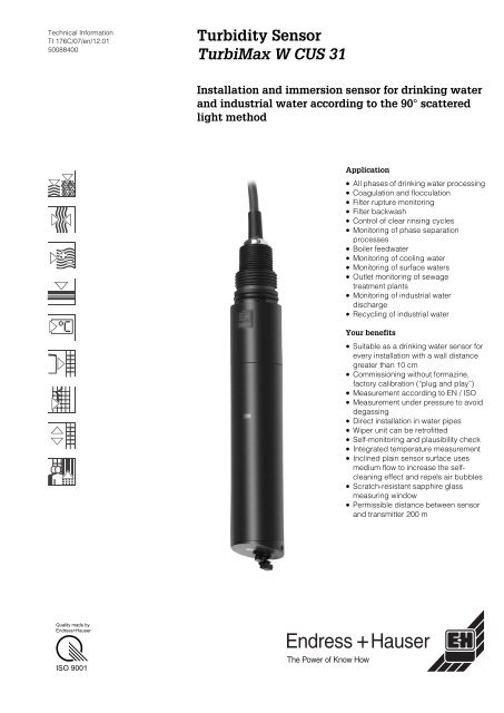
<strong>Turbidity</strong> <strong>Sensor</strong><br />
TurbiMax W CUS 31<br />
Installation and immersion sensor for drinking water<br />
and industrial water according to the 90° scattered<br />
light method<br />
Application<br />
• All phases of drinking water processing<br />
• Coagulation and flocculation<br />
• Filter rupture monitoring<br />
• Filter backwash<br />
• Control of clear rinsing cycles<br />
• Monitoring of phase separation<br />
processes<br />
• Boiler feedwater<br />
• Monitoring of cooling water<br />
• Monitoring of surface waters<br />
• Outlet monitoring of sewage<br />
treatment plants<br />
• Monitoring of industrial water<br />
discharge<br />
• Recycling of industrial water<br />
Your benefits<br />
• Suitable as a drinking water sensor for<br />
every installation with a wall distance<br />
greater than 10 cm<br />
• Commissioning without formazine,<br />
factory calibration (“plug and play”)<br />
• Measurement according to EN / ISO<br />
• Measurement under pressure to avoid<br />
degassing<br />
• Direct installation in water pipes<br />
• Wiper unit can be retrofitted<br />
• Self-monitoring and plausibility check<br />
• Integrated temperature measurement<br />
• Inclined plain sensor surface uses<br />
medium flow to increase the selfcleaning<br />
effect and repels air bubbles<br />
• Scratch-resistant sapphire glass<br />
measuring window<br />
• Permissible distance between sensor<br />
and transmitter 200 m<br />
Quality made by<br />
Endress+Hauser<br />
ISO 9001
Function and system design<br />
Measuring principle Nephelometric measuring principle 90° NIR scattered light according to EN 27027<br />
The 90° scattered light method with a wavelength in the near-infrared range (880 nm) according<br />
to ISO 7027 / EN 27027 records turbidity values under standardised, comparable conditions. A<br />
temperature signal is also recorded and transmitted in addition to the turbidity signal. The<br />
excitation radiation of an infrared transmitter (Fig., Item 1) strikes the medium at a defined angle<br />
of beam. The different refractions of light between the entrance window and the medium (water)<br />
are taken into account.<br />
Particles in the medium (Item 5) create a scattered radiation which strikes the scattered light<br />
receivers (Items 3, 4) at a defined angle of beam. The measurement in the medium is constantly<br />
compared with the values of a reference receiver (Item 2). Digital filter functions with excellent<br />
interference signal suppression and sensor self-monitoring ensure additional measurement<br />
reliability.<br />
2 3 4<br />
1<br />
A<br />
A<br />
1<br />
2<br />
3<br />
4<br />
5<br />
B<br />
Side view of the sensor (cutaway scheme)<br />
Infrared transmitter<br />
Reference diode<br />
Scattered light receiver 1<br />
Scattered light receiver 2<br />
Particles in the medium<br />
Top view of the sensor surface with optical<br />
windows<br />
5<br />
90 °<br />
B<br />
1<br />
3 4<br />
C07-CUS31xxx-15-05-00-xx-001.EPS<br />
<strong>Turbidity</strong> measurement according to<br />
ISO 7027 / EN 27027<br />
Wavelength<br />
880 nm<br />
Radiation compensation<br />
Using reference photodiodes<br />
Factory calibration Traceable to formazine standard and SiO 2<br />
2 Endress+Hauser
12.3 C<br />
Measuring system<br />
A measuring system consists of:<br />
• <strong>Turbidity</strong> sensor CUS 31 in an assembly<br />
• Transmitter, e.g. Liquisys M CUM 223/253<br />
Optional:<br />
• CYH 101 universal suspended assembly holder for immersion operation<br />
• DipFit W CYA 611 immersion assembly or FlowFit W CUA 250 flow assembly<br />
or ProbFit W CUA 461 retractable assembly<br />
• VBM junction box<br />
• ChemoClean automatic spray cleaning system<br />
NTU<br />
FNU<br />
0.127 R262<br />
1<br />
4<br />
3<br />
1<br />
2<br />
C07-CUS31xxx-14-05-00-xx-001.EPS<br />
4<br />
3<br />
2<br />
C07-CUS31xxx-14-05-00-xx-002.EPS<br />
Flow measurement<br />
1 Transmitter, e.g. Liquisys M CUM 253<br />
2 <strong>Sensor</strong> cable<br />
3 TurbiMax W CUS 31<br />
4 Flow assembly S, (see Page 6)<br />
Measuring system with immersion assembly<br />
1<br />
2<br />
3<br />
4<br />
Transmitter, e.g. Liquisys M CUM 253<br />
CYH 101 assembly holder<br />
(with CYY 101 weather protection cover)<br />
TurbiMax W CUS 31<br />
DipFit W CYA 611 immersion assembly<br />
Input<br />
Measured variable<br />
<strong>Turbidity</strong><br />
Measuring range 0.000 ... 9999 FNU / 0.00 ... 3000 ppm / 0.0 ... 3.0 g/l / 0.0 ... 200.0 %<br />
Electrical connection<br />
Cable connection<br />
<strong>Sensor</strong><br />
Screen<br />
Pin CUM 2x3<br />
S<br />
GN<br />
YE<br />
WH<br />
BN<br />
Com A<br />
Com B<br />
–U B<br />
+U B<br />
96<br />
97<br />
88<br />
87<br />
C07-CUS31xxx-04-05-00-en-002.EPS<br />
CUS 31 cable assignment, for sensor and transmitter<br />
Cable type<br />
CYK 81, four-core, screened fixed cable (2x2 cores twisted) with free cable ends<br />
Endress+Hauser 3
Operating conditions (installation)<br />
Installation instructions<br />
• Each sensor is calibrated in the factory according to standard procedures<br />
(ISO 7027 / EN 27027).<br />
• The calibration data are stored in the sensor.<br />
• Customer-specific or material-specific calibrations can also be stored.<br />
• The calibration values are listed in a quality certificate which is enclosed individually in the<br />
packaging with each sensor.<br />
• <strong>Sensor</strong> systems with assemblies are available to meet the requirements of the drinking water<br />
sector. The sensor is already installed in the assembly and is calibrated with the assembly.<br />
• Various assemblies are available for the industrial water sector.<br />
• Installing the sensor in piping or very close to a wall can cause backscatter which results in a<br />
higher signal.<br />
To compensate for this factor, an installation adjustment may have to be performed by means<br />
of the transmitter, (see Operating Instructions for Liquisys M CUM 2x3, BA 200C/07/en).<br />
FNU<br />
100<br />
dark wall or bottom<br />
(non-reflecting)<br />
10<br />
1<br />
0.1<br />
0.01<br />
0<br />
5 10 15 20<br />
bright wall or bottom<br />
(reflecting)<br />
distance / cm<br />
C07-CUS31xxx-05-05-00-en-001.EPS<br />
Effect of the distance from the wall or bottom<br />
Installation in<br />
immersion assemblies<br />
When installing the CUS 31 in immersion assemblies, such as CYA 611 with pendulum frame, please<br />
ensure that a sufficient wall distance is observed during operation. For this reason, select an<br />
installation location in which a minimum wall distance of 15 cm is observed even with varying<br />
levels or altered flow profiles. Mounting in a suspended assembly with chain must therefore be<br />
avoided.<br />
The sensor must immerse at least 4 cm into the medium.<br />
1490<br />
1500<br />
C07-CUS31xxx-11-05-00-xx-002.EPS<br />
950<br />
450<br />
150<br />
120<br />
2000<br />
C07-CUS31xxx-11-05-00-xx-001.EPS<br />
CUS 31 in CYA 611 assembly with pendulum frame<br />
CYH 101 assembly holder with CYA 611 assembly<br />
4 Endress+Hauser
Pipe installation<br />
The following diagram illustrates various installation positions in piping and indicates whether they<br />
are permitted or not.<br />
1<br />
Detail A,<br />
(top view)<br />
Detail A, rotated<br />
(side view)<br />
1<br />
90°<br />
3<br />
2<br />
5<br />
4<br />
2<br />
C07-CUS31xxx-11-05-00-en-001.EPS<br />
Orientation and installation positions of CUS 31 with CUA 120-A/B adapter or with CUA 461 retractable<br />
assembly<br />
• The pipeline diameter must be at least DN 100 if reflective materials<br />
(e.g. stainless steel) are used.<br />
• Install the sensor in places with uniform flow conditions and not in places where air may collect<br />
or foam bubbles form (1) or where suspended particles may settle (2).<br />
• The best installation location is in the ascending pipe (3). Installation is also possible in the<br />
horizontal pipe (4), but should be avoided in the down pipe (5).<br />
• Orientate the sensor surface against the medium flow (“self-cleaning effect”).<br />
Installation in<br />
flow assemblies<br />
Install the sensor according to the instructions provided in the Technical Information of the<br />
FlowFit W CUA 250 flow assembly (TI 096C/07/en).<br />
• If possible, install the flow assembly vertically so that the medium flows to the sensor from<br />
below. Alternatively, the assembly can also be installed horizontally.<br />
• Two sensor orientations are possible for horizontal installation, (Figure):<br />
– parallel to the medium flow<br />
– against the medium flow<br />
• Orientation parallel to the medium flow is required when using the CUR 3 spray head.<br />
• Orientation against the medium flow is used to increase the self-cleaning effect in heavily-soiled<br />
media (> 15 FNU). The wall reflection is negligible here due to the high absorption tendency.<br />
We recommend the CUS 31-xxE or CUS 31-xxS sensor version be used for turbidities < 5 FNU.<br />
Parallel sensor orientation<br />
↑ Medium flow direction<br />
<strong>Sensor</strong> orientation against the medium flow<br />
Endress+Hauser 5
Use in the drinking water<br />
sector with specific<br />
calibration<br />
When the CUS 31 sensor is ordered with assembly E or S, the sensor is individually calibrated<br />
in the factory with the assembly ordered.<br />
Therefore, no initial calibration on site is necessary.<br />
396<br />
Detail A<br />
275<br />
Detail A<br />
¾"<br />
25<br />
19<br />
C07-CUS31xxx-06-07-00-xx-002.EPS<br />
Flow assembly E<br />
(without gas bubble trap)<br />
Flow assembly S<br />
(with gas bubble trap)<br />
• In-flow and out-flow is vertical if assembly E is installed, (flow direction from bottom to top, see<br />
left-hand diagram), and horizontal if assembly S is installed (right-hand diagram).<br />
• The inlet and outlet pipes (nominal diameter DN 20) are each glued into the PVC adhesive<br />
threaded joints. A wall support can be mounted if necessary.<br />
• The minimum flow for assembly S is 50 l/h.<br />
Recommended<br />
installation with<br />
assembly E or S<br />
Permissible and impermissible sensor installation positions in flow assembly E or S<br />
6 Endress+Hauser
Gas bubble elimination<br />
Conventional turbidity measurements are carried out in an unpressurised sample. When the<br />
pressure on a sample (which was pressurised beforehand) is released, fine bubbles are<br />
produced which distort the turbidity measurement.<br />
There are several methods of eliminating these gas bubbles:<br />
• Pressurised measurement in the bypass (pressure is not released until after the measurement).<br />
• For measurements without overpressure or with slight overpressure:<br />
Free medium flow above the assembly level. The mounting location should be as low as<br />
possible to take advantage of the maximum possible pressure.<br />
• Unpressurised measurement and gas bubble elimination using wiper cleaning.<br />
The wiping duration and interval can be programmed for optimum results.<br />
• Reduction of the flow to the lowest possible value (50 l/h, CUS 31-xxS).<br />
Slight flow prolongs the period in which the medium is in the assembly. This means that gas<br />
bubbles have more time to rise to the top. The sensor response time increases slightly due to<br />
the lower flow.<br />
• Flow assembly S with integrated gas bubble trap (Figure below)<br />
Most of the gas bubbles are sent directly to the assembly outlet in the upper half of the<br />
separated inlet (7). The other half of the medium flows into a ring channel (1) by means of the<br />
central pipe. The remaining bubbles rise here and are conveyed out of the measuring chamber<br />
by means of holes in the outlet (2) located in the centre of the assembly. Bubble-free medium<br />
(3) is pushed down into the measuring chamber (5). This also leads to a high flow which results<br />
in a quick response time. In addition, this almost completely prevents dirt particles settling.<br />
1<br />
2<br />
3<br />
4<br />
5<br />
6<br />
7<br />
Ring channel<br />
Outlet from the measuring chamber<br />
Bubble-free medium<br />
Drain screw<br />
Measuring chamber<br />
CUS 31 sensor<br />
Separated inlet<br />
Flow assembly S with integrated gas bubble trap<br />
(assembly S)<br />
Performance characteristics<br />
Maximum measured error<br />
< 5 % (min. 0.02 FNU) of the measured value<br />
(system measured error related to the primary formazine standard / tracing according to<br />
ISO 5725 and ISO 7027 / EN 27027)<br />
Repeatability<br />
< 1 % (min. 0.01 FNU) of the measured value<br />
Storage temperature –20 ... +60 °C<br />
Ingress protection IP 68<br />
Operating conditions (environment)<br />
Endress+Hauser 7
Process temperature range –5 ... +50 °C<br />
Operating conditions (process)<br />
Process pressure range<br />
(temperature-dependent)<br />
1 bar (50 °C) ... 6 bar (25 °C)<br />
Process connection G1 and NPT ¾”<br />
Design, dimensions<br />
1<br />
2<br />
3<br />
4<br />
Mechanical construction<br />
5<br />
1<br />
2<br />
Ø40<br />
6<br />
C07-CUS31xxx-06-05-00-xx-001.EPS<br />
3 4<br />
C07-CUS31xxx-16-05-06-xx-001.EPS<br />
CUS 31 sensor<br />
<strong>Sensor</strong> surface with optical windows<br />
1 Fixed cable 1 Photodiode (receiver diode)<br />
2 NPT ¾”- thread 2 Wiper (optional)<br />
3 G1 - thread 3 Photodiode (receiver diode)<br />
4 O-ring 4 LED (IR transmitter diode)<br />
5 <strong>Sensor</strong> shaft<br />
6 <strong>Sensor</strong> surface with optical windows<br />
Wiper cleaning<br />
(optional)<br />
The CUS 31-W sensor is equipped with a rubber wiper for removing deposits from the sensor<br />
carrier plate. The cleaning times and intervals are controlled by means of the transmitter<br />
(Liquisys M CUM 223/253).<br />
Temperature sensor NTC-resistance 30K at 25 °C<br />
Materials<br />
<strong>Sensor</strong> carrier plate, shaft<br />
Optical windows<br />
Flow assemblies E and S<br />
Cable<br />
PVC / PPS GF 40 (polyphenylene sulfide with 40 % glass-fibre)<br />
Sapphire<br />
PVC<br />
TPEO –40 ... 130 °C (elastomer on polyolefine base)<br />
8 Endress+Hauser
Certificates and approvals<br />
Quality certificate<br />
Each sensor has an individual quality certificate with information on the sensor identification and<br />
calibration according to ISO 7027 / EN 27027.<br />
The quality certificate is enclosed with each sensor in the packaging.<br />
Ordering information<br />
Product structure<br />
TurbiMax W CUS 31<br />
<strong>Sensor</strong><br />
A <strong>Sensor</strong> in standard version<br />
W <strong>Sensor</strong> with integrated wiper<br />
Cable length<br />
2 Connecting cable 7 m<br />
4 Connecting cable 15 m<br />
9 Connecting cable to customer’s specifications<br />
Assembly<br />
A Without assembly<br />
E Assembly for bubble-free media<br />
S Assembly with integrated gas bubble elimination<br />
CUS 31-<br />
Complete order code<br />
Endress+Hauser 9


