Verilog 2 - Brown University
Verilog 2 - Brown University
Verilog 2 - Brown University

Create successful ePaper yourself
Turn your PDF publications into a flip-book with our unique Google optimized e-Paper software.
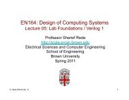
EN164: Design of Computing Systems<br />
Lecture 06: Lab Foundations / <strong>Verilog</strong> 2<br />
Professor Sherief Reda<br />
http://scale.engin.brown.edu<br />
Electrical Sciences and Computer Engineering<br />
School of Engineering<br />
<strong>Brown</strong> <strong>University</strong><br />
Spring 2011<br />
S. Reda EN164 Sp ‘11<br />
1
2. Dataflow modeling<br />
• Module is designed by specifying the data flow, where the designer<br />
is aware of how data flows between hardware registers and how the<br />
data is processed in the design<br />
• The continuous assignment is one of the main constructs used in<br />
dataflow modeling<br />
assign out = i1 & i2; <br />
assign addr[15:0] = addr1[15:0] ^ addr2[15:0]; <br />
assign {c_out, sum[3:0]}=a[3:0]+b[3:0]+c_in;<br />
• A continuous assignment is always active and the assignment<br />
expression is evaluated as soon as one of the right-hand-side<br />
variables change<br />
• Assign statements describe hardware that operates concurrently −<br />
ordering does not matter<br />
• Left-hand side must be a scalar or vector net. Right-hand side<br />
operands can be wires, (registers, integers, and real)<br />
S. Reda EN164 Sp ‘11 2
Operator types in dataflow expressions<br />
• Operators are similar to C except that there are no ++ or –<br />
• Arithmetic: *, /, +, -, % and **<br />
• Logical: !, && and ||<br />
• Relational: >, = and <br />
• Concatenation: { }<br />
• Replication: {{}}<br />
• Conditional: ?:<br />
S. Reda EN164 Sp ‘11 3
Examples of 2x1 MUX and 4x1 MUX<br />
module mux2to1(s, a, b, y); <br />
output y; <br />
input s, a, b; <br />
assign y = (b & s) | ( a & ~s); <br />
// OR THIS WAY <br />
assign y = s ? b : a; <br />
endmodule <br />
module mux4to1(out, i0, i1, i2, i3, s1, s0); <br />
output out; <br />
input i0, i1, i2, i3; <br />
output s1, s0; <br />
assign out = (~s1 & ~s0 & i0) | <br />
(~s1 & s0 & i1) | <br />
(s1 & ~s0 & i2) | <br />
(s1 & s0 & i3); <br />
// OR THIS WAY <br />
assign out = s1 ? (s0 ? i3:i2) : (s0 ? i1:i0); <br />
endmodule <br />
S. Reda EN164 Sp ‘11 4
Difference between HLL and <strong>Verilog</strong> assign<br />
[Example from Thornton & Reese]<br />
S. Reda EN164 Sp ‘11 5
Difference between HLL and <strong>Verilog</strong> assign<br />
can only work with tri-state drivers<br />
[Example from Thornton & Reese]<br />
S. Reda EN164 Sp ‘11 6
Example of a dataflow 4-bit adder<br />
[Example from Thornton & Reese]<br />
S. Reda EN164 Sp ‘11 7
3. Behavioral modeling<br />
• Design is expressed in algorithmic level, which<br />
frees designers from thinking in terms of logic<br />
gates or data flow.<br />
• All algorithmic or procedural statements in<br />
<strong>Verilog</strong> can appear only inside two statements:<br />
always and initial.<br />
• Each always and initial statement<br />
represents a separate activity flow in <strong>Verilog</strong>.<br />
Remember that activity flows in <strong>Verilog</strong> run in<br />
parallel.<br />
• You can have multiple initial and always<br />
statements but you can’t nest them.<br />
. <br />
. <br />
reg a, b, c; <br />
initial a=1’b0; <br />
. <br />
. <br />
always @* <br />
begin <br />
b = a ^ 1’b1; <br />
c = a + b; <br />
end <br />
. <br />
. <br />
S. Reda EN164 Sp ‘11 8
Data types<br />
• A reg is a <strong>Verilog</strong> variable type and does not necessarily imply a<br />
physical register. Think of it as a variable or place holder. It is<br />
unsigned by default.<br />
reg clock;!<br />
reg [0:40] virt_address;!<br />
• Register arrays or memories. Used to model register files, RAMs<br />
and ROMs. Modeled in <strong>Verilog</strong> as a one-dimensional array of<br />
registers. Examples.<br />
reg mem1bit[0:1023]; <br />
reg [7:0] membyte[0:1023]; <br />
accessing: membyte[511]; <br />
• Parameters. Define constants and cannot be used as variables.<br />
parameter port_id=5; <br />
S. Reda EN164 Sp ‘11<br />
9
Data types<br />
• integers (signed) and reals. They are type of reg.<br />
real delta; <br />
integer i; <br />
initial <br />
begin <br />
delta = 4e10; <br />
i = 4; <br />
end <br />
• Arrays of integers and real.<br />
integer count[0:7]; <br />
integer matrix[4:0][0:255]; <br />
• Strings can be stored in reg. The width of the register variables must<br />
be large enough to hold the string.<br />
reg [8*19:1] string_value; <br />
initial <br />
string_value = “Hello <strong>Verilog</strong> World”; <br />
S. Reda EN164 Sp ‘11<br />
10
initial statements<br />
• An initial block start at time 0, executes exactly once and<br />
then never again.<br />
• If there are multiple initial blocks, each blocks starts to<br />
execute concurrently at time 0 and each blocks finish execution<br />
independently of the others.<br />
• Multiple behavioral statements must be grouped using begin<br />
and end. If there is one statement then grouping is not<br />
necessary.<br />
In procedural statements (initial, always)<br />
LHS must be of type registers (and its<br />
derivatives)<br />
reg x, y, m; <br />
initial m=1’b0; <br />
initial <br />
begin <br />
x = 1’b0; <br />
y = 1’b1; <br />
end <br />
S. Reda EN164 Sp ‘11 11
always statements<br />
• The always statement starts at time 0 and<br />
executes the statements in the always<br />
block when the events in its sensitivity list<br />
occur<br />
• Powerful constructs like if, if-else, case,<br />
and looping are only allowed inside always<br />
blocks.<br />
• always statements can be used to<br />
implement both combinational or<br />
sequential logic<br />
• Multiple behavioral statements must be<br />
grouped using begin and end.<br />
• Multiple always statement can appear in<br />
a module<br />
S. Reda EN164 Sp ‘11 12
Sensitivity list of events<br />
• An event is the change in the value on a<br />
register or a net. Events can be utilized<br />
to trigger the execution of a statement of<br />
a block of statements.<br />
• The @ symbol is used to specify an<br />
event control.<br />
• For combinational logic, any net that<br />
appears on the right side of an “ =”<br />
operator in the always block should be<br />
included in the event list.<br />
• [for sequential – ignore for now]<br />
Statements can be executed on changes<br />
in signal value or at a positive (posedge)<br />
or negative (negedge) transition of the<br />
signal.<br />
S. Reda EN164 Sp ‘11 13
always statements<br />
• Any net that is assigned within an always block must be declared as<br />
a reg type; this does not imply that this net is driven by a register or<br />
sequential logic.<br />
• The “=” operator when used in an always block is called a blocking<br />
assignment<br />
• If there is some logic path through the always block that does not<br />
assign a value to the output net then a latch is inferred<br />
• The logic synthesized assumed the blocking assignments are<br />
evaluated sequentially. This means that the order in which<br />
assignments are written in an always blocks affects the logic that is<br />
synthesized.<br />
S. Reda EN164 Sp ‘11 14
always statements<br />
• Because of the sequential nature of an always block, the same net<br />
can be assigned multiple times in an always block; the last<br />
assignment takes precedence.<br />
[Example from Thornton & Reese]<br />
S. Reda EN164 Sp ‘11 15
Conditional statements<br />
• Very similar to C<br />
• Can always appear inside<br />
always and initial blocks<br />
. <br />
if(x) <br />
begin <br />
y= 1’b1; <br />
z= 1’b0; <br />
end <br />
. <br />
expression<br />
if (count < 10) <br />
count = count+1; <br />
else <br />
count = 0; <br />
. <br />
. <br />
if(alu_control == 0) <br />
y = x + z; <br />
else if (alu_control == 1) <br />
y = x – z; <br />
else if (alu_control == 2) <br />
y = x * z; <br />
else <br />
y = x; <br />
. <br />
reg [1:0] alu_control; <br />
.. <br />
case (alu_control) <br />
2’d0 : y = x + z; <br />
2’d1 : y = x – z; <br />
2’d2 : y = x * z; <br />
default: y=x; <br />
endcase <br />
S. Reda EN164 Sp ‘11 16
Example: Mux4x1<br />
module mux4x1(out, i0, i1, i2, i3, s1, s0); <br />
output out; <br />
input i0, i1, i2, i3; <br />
input s1, s0; <br />
reg out; <br />
always @(s1 or s0 or i0 or i1 or i2 or i3) <br />
begin <br />
case({s1, s0}) <br />
2’d0: out = i0; <br />
2’d1: out = i1; <br />
2’d2: out = i2; <br />
2’d3: out = i3; <br />
endcase <br />
endmodule <br />
S. Reda EN164 Sp ‘11 17
Level sensitive latch (D-Latch)<br />
• The <strong>Verilog</strong> implementation of a D-latch is an always block that<br />
makes a nonblocking assignment (“
Edge-triggered storage element (D-FF)<br />
• The @ symbol is used to specify an<br />
event control.<br />
• Statements can be executed on<br />
changes in signal value or at a<br />
positive (posedge) or negative<br />
(negedge) transition of the signal.<br />
• In general, edge-triggered storage<br />
elements are preferred to levelsensitive<br />
storage elements because<br />
of simpler timing requirements<br />
• The 1-bit edge-triggered storage<br />
elements provided by FPGA<br />
vendors are DFFs because of their<br />
simplicity and speed.<br />
[Thornton & Reese]<br />
S. Reda EN164 Sp ‘11 19
Example from question (3) from Lab 1<br />
module quest3(CLOCK_50, LEDR);!<br />
input CLOCK_50;!<br />
output reg [17:0] LEDR;!<br />
integer count;!<br />
always @(posedge CLOCK_50)!<br />
begin!<br />
!if(count == 50000000)!<br />
! !begin!<br />
! ! !LEDR[0]