Accurate Determination of Stress Intensity Factor for Interface Crack ...
Accurate Determination of Stress Intensity Factor for Interface Crack ...
Accurate Determination of Stress Intensity Factor for Interface Crack ...

You also want an ePaper? Increase the reach of your titles
YUMPU automatically turns print PDFs into web optimized ePapers that Google loves.
Key Engineering Materials Vols. 353-358 (2007) pp 3124-3127<br />
Online available since 2007/Sep/10 at www.scientific.net<br />
© (2007) Trans Tech Publications, Switzerland<br />
doi:10.4028/www.scientific.net/KEM.353-358.3124<br />
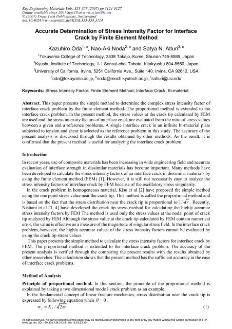
<strong>Accurate</strong> <strong>Determination</strong> <strong>of</strong> <strong>Stress</strong> <strong>Intensity</strong> <strong>Factor</strong> <strong>for</strong> <strong>Interface</strong><br />
<strong>Crack</strong> by Finite Element Method<br />
Kazuhiro Oda 1, a , Nao-Aki Noda 2, b and Satya N. Atluri 3, c<br />
1 Tokuyama College <strong>of</strong> Technology, 3538 Takajo, Kume, Shunan 745-8585, Japan<br />
2 Kyushu Institute <strong>of</strong> Technology, 1-1 Sensui-cho, Tobata, Kitakyushu 804-8550, Japan<br />
3 University <strong>of</strong> Cali<strong>for</strong>nia, Irvine, 5251 Cali<strong>for</strong>nia Ave., Suite 140, Irvine, CA 92612, USA<br />
a oda@tokuyama.ac.jp, b noda@mech.kyutech.ac.jp, c satluri@uci.edu<br />
Keywords: <strong>Stress</strong> <strong>Intensity</strong> <strong>Factor</strong>; Finite Element Method; <strong>Interface</strong> <strong>Crack</strong>; Bi-material.<br />
Abstract. This paper presents the simple method to determine the complex stress intensity factor <strong>of</strong><br />
interface crack problem by the finite element method. The proportional method is extended to the<br />
interface crack problem. In the present method, the stress values at the crack tip calculated by FEM<br />
are used and the stress intensity factors <strong>of</strong> interface crack are evaluated from the ratio <strong>of</strong> stress values<br />
between a given and a reference problems. A single interface crack in an infinite bi-material plate<br />
subjected to tension and shear is selected as the reference problem in this study. The accuracy <strong>of</strong> the<br />
present analysis is discussed through the results obtained by other methods. As the result, it is<br />
confirmed that the present method is useful <strong>for</strong> analyzing the interface crack problem.<br />
Introduction<br />
In recent years, use <strong>of</strong> composite materials has been increasing in wide engineering field and accurate<br />
evaluation <strong>of</strong> interface strength in dissimilar materials has become important. Many methods have<br />
been developed to calculate the stress intensity factors <strong>of</strong> an interface crack in dissimilar materials by<br />
using the finite element method (FEM) [1]. However, it is still not necessarily easy to analyze the<br />
stress intensity factors <strong>of</strong> interface crack by FEM because <strong>of</strong> the oscillatory stress singularity.<br />
In the crack problem in homogeneous material, Kisu et al [2] have proposed the simple method<br />
using the one point stress value near the crack tip. This method is called the proportional method and<br />
is based on the fact that the stress distribution near the crack tip is proportional to 1 / r . Recently,<br />
Nisitani et al [3, 4] have developed the crack tip stress method <strong>for</strong> calculating the highly accurate<br />
stress intensity factors by FEM The method is used only the stress values at the nodal point <strong>of</strong> crack<br />
tip analyzed by FEM Although the stress value at the crack tip calculated by FEM contain numerical<br />
error, the value is effective as a measure <strong>of</strong> the magnitude <strong>of</strong> singular stress field. In the interface crack<br />
problem, however, the highly accurate values <strong>of</strong> the stress intensity factors cannot be evaluated by<br />
using the crack tip stress values.<br />
This paper presents the simple method to calculate the stress intensity factors <strong>for</strong> interface crack by<br />
FEM. The proportional method is extended to the interface crack problem. The accuracy <strong>of</strong> the<br />
present analysis is verified through the comparing the present results with the results obtained by<br />
other researches. The calculation shows that the present method has the sufficient accuracy in the case<br />
<strong>of</strong> interface crack problems.<br />
Method <strong>of</strong> Analysis<br />
Principle <strong>of</strong> proportional method. In this section, the principle <strong>of</strong> the proportional method is<br />
explained by taking a two dimensional mode I crack problem as an example.<br />
In the fundamental concept <strong>of</strong> linear fracture mechanics, stress distribution near the crack tip is<br />
expressed by following equation when θ = 0 .<br />
σ = / 2πr<br />
(1)<br />
y<br />
K I<br />
All rights reserved. No part <strong>of</strong> contents <strong>of</strong> this paper may be reproduced or transmitted in any <strong>for</strong>m or by any means without the written permission <strong>of</strong> TTP,<br />
www.ttp.net. (ID: 169.234.136.213-21/01/13,03:23:10)
Key Engineering Materials Vols. 353-358 3125<br />
When the distance from crack tip r= r 0 ,<br />
K<br />
I<br />
/ σ is constant and the next relation between two<br />
y<br />
different problems can be obtained theoretically.<br />
K * / σ * = K / σ<br />
(2)<br />
I<br />
y<br />
I<br />
y<br />
If the stress intensity factor K 1 * <strong>of</strong> the reference problem is known, we can easily obtained the K 1 <strong>of</strong><br />
given problem from the relation (2) because the stresses σ<br />
y<br />
* and σ<br />
y<br />
<strong>of</strong> reference and given<br />
problems can be calculated by FEM.<br />
In the interface crack problem, however, the highly accurate values <strong>of</strong> the stress intensity factors<br />
cannot be obtained by using the stress values near the interface crack tip because the elastic solution <strong>of</strong><br />
the interface crack has an oscillatory stress singularity.<br />
Application <strong>of</strong> proportional method to interface crack problem. In this study, the proportional<br />
method is extended to interface crack problem. In the ordinary extrapolation method <strong>of</strong> interface<br />
crack problem, the stress intensity factors are evaluated by the following equations.<br />
⎛ τ<br />
xy<br />
⎞<br />
⎛ σ<br />
y<br />
⎞<br />
K = r ⎜ Q + Q⎟<br />
1<br />
lim 2π σ<br />
y<br />
cos sin , K<br />
⎜<br />
⎟<br />
r→0<br />
2<br />
= lim 2π rτ<br />
xy<br />
τ Q − Q<br />
⎝ σ<br />
→<br />
xy<br />
cos sin<br />
(3)<br />
r 0<br />
y ⎠<br />
⎝ τ<br />
xy ⎠<br />
⎛ r ⎞ 1 ⎡ κ1<br />
1 κ1<br />
1 ⎤<br />
Q = ε ln⎜<br />
⎟ , ε = ln⎢(<br />
+ ) /( + ) ⎥ ,<br />
⎝ 2a<br />
⎠ 2π<br />
⎣ G1<br />
G2<br />
G1<br />
G2<br />
⎦<br />
κ<br />
j<br />
= ( 3 −ν<br />
j<br />
) /(1 + ν<br />
j<br />
) Plane stress, κ<br />
j<br />
= 3 − 4ν<br />
j<br />
Plane strain (j=1, 2) (4)<br />
where G j and ν<br />
j<br />
are shear modulus and Poisson’s ratio <strong>of</strong> material j (j=1, 2) and ε is oscillation<br />
index. If ε = ε * and τ σ = τ * / σ * at r=r 0 , the oscillatory terms in Eq.(3) are the same<br />
xy<br />
/<br />
y xy y<br />
between two different problems. Then, Eq. (5) is obtained, as well as homogeneous crack problem.<br />
K / σ * = K / σ , K * / τ * K / τ<br />
(5)<br />
1<br />
*<br />
y 1 y 2 xy<br />
=<br />
2<br />
xy<br />
Eq. (5) is based on the similar stress distributions near the interface crack tip and the asterisk * means<br />
the reference problem. In FEM analysis, we use the next condition in order to obtain the similar stress<br />
distributions near the interface crack.<br />
τ<br />
xy,<br />
FEM<br />
* τ<br />
xy,<br />
FEM<br />
= (6)<br />
σ * σ<br />
y,<br />
FEM<br />
y,<br />
FEM<br />
Here, the values <strong>of</strong> σ y,FEM * , τ xy,FEM * and σ y, FEM , τ xy, FEM are the stress values calculated by FEM.<br />
It is noted that the same analysis conditions, that is the same material constants, the same crack length<br />
and the same mesh pattern near crack tip, have to be used in the calculation <strong>of</strong> σ y,FEM * , τ xy,FEM * and<br />
σ y,FEM , τ xy, FEM<br />
. There<strong>for</strong>e, the SIFs <strong>of</strong> the given problem can be easily evaluated from<br />
σ<br />
y,<br />
FEM<br />
τ<br />
xy,<br />
FEM<br />
K 1<br />
≒ K * , K *<br />
σ * 1<br />
2<br />
≒ K<br />
(7)<br />
τ * 2<br />
y,<br />
FEM<br />
xy,<br />
FEM<br />
T=1<br />
S<br />
G 1 ,ν 1<br />
σ<br />
G 1 , ν 1<br />
2a<br />
a<br />
Minimum element = a/243<br />
G 2 , ν 2<br />
G 2 ,ν 2<br />
w<br />
1.5w<br />
<strong>Crack</strong> tip<br />
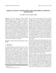
Fig.1 Reference problem (K 1 *, K 2 * are known) Fig.2 Given problem and FEM mesh pattern<br />
In this study, K 1 * and K 2 * <strong>of</strong> a reference problem (Fig.1) are given by the exact solution <strong>of</strong> single<br />
interface crack in an infinite dissimilar plate subjected to tension T and shear S.
3126 Progresses in Fracture and Strength <strong>of</strong> Materials and Structures<br />
K * *<br />
1<br />
+ iK<br />
2<br />
= ( T + iS)<br />
πa<br />
(1 + 2iε<br />
)<br />
(8)<br />
The loading stresses T and S in reference problem as shown in Fig.1 are determined from the Eq.(6).<br />
<strong>Determination</strong> <strong>of</strong> loading stresses. As reference problem, an interface crack in an infinite<br />
bi-material plate subjected to tension and shear loads (Fig.1) is used in this study. Actually, this plate<br />
is a square bi-material plate with an interface crack whose width is 1500 times <strong>of</strong> the crack size. In<br />
order to determine the T and S, a reference problem is expressed by superposing tension and shear<br />
problems. The stresses near interface crack tip in bonded dissimilar materials subjected to the loads T<br />
and S are expressed by<br />
T = 1<br />
S = 1<br />
T = 1<br />
S = 1<br />
σ * = σ * ⋅T<br />
+ * ⋅S<br />
, τ * = τ * ⋅T<br />
+ * ⋅S<br />
(9)<br />
y, FEM y,<br />
FEM<br />
σ<br />
y,<br />
FEM<br />
xy, FEM xy,<br />
FEM<br />
τ<br />
xy,<br />
FEM<br />
T = 1<br />
where σ<br />
y,<br />
FEM<br />
is the stress σ<br />
y<br />
<strong>of</strong> a tension problem analyzed by FEM when T=1 and S=0.<br />
By substituting the expressions (9) into Eq.(6), we obtain the loading stress S when T=1.<br />
T = 1<br />
S = 1 T = 1<br />
S σ<br />
y,<br />
FEM<br />
⋅τ<br />
xy,<br />
FEM<br />
* −τ<br />
xy,<br />
FEM<br />
* ⋅σ<br />
y,<br />
FEM<br />
*<br />
=<br />
T = 1<br />
S = 1<br />
T τ ⋅σ<br />
* −σ<br />
⋅τ<br />
*<br />
xy,<br />
FEM<br />
y,<br />
FEM<br />
y,<br />
FEM<br />
xy,<br />
FEM<br />
The stress intensity factors <strong>of</strong> given problem are calculated by Eqs. (7), (8) and (10).<br />
Results and discussions<br />
The finite dissimilar plate with a single edge interface crack is analyzed to examine the usefulness <strong>of</strong><br />
the present method. Fig.2 shows the problem <strong>of</strong> the finite bonded plate with edge interface crack and<br />
FEM mesh pattern. The minimum element size at the crack tip is a/243. The elements near the crack<br />
tip are made fine systematically. It should be noted that the same mesh patterns near the crack tip have<br />
to be used in the calculation <strong>of</strong> stress values <strong>for</strong> the given and reference problems.<br />
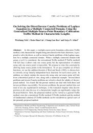
Fig.3 shows the relative stress distributions near the interface crack tip. Here, σ<br />
y 0,<br />
FEM<br />
and τ<br />
xy 0,<br />
FEM<br />
are stress values at the crack tip node obtained by FEM, and σ<br />
y, FEM<br />
and τ<br />
xy, FEM<br />
are at any nodes. In<br />
these cases, the ratio G 2 /G 1 is 10, and the relative crack length a/w is 0.1. As shown in these figures,<br />
when the condition (6) is satisfied, the relative stress distributions <strong>of</strong> given and reference problems<br />
coincide with each other. From this figure, it is seen that the singular stress field <strong>of</strong> the interface crack<br />
is controlled by τ<br />
xy 0 , FEM<br />
/σ<br />
xy 0,<br />
FEM<br />
at the crack tip calculated by FEM.<br />
(10)<br />
σ<br />
σ<br />
τ<br />
τ<br />
y,<br />
FEM<br />
y0.<br />
FEM<br />
xy,<br />
FEM<br />
xy0,<br />
FEM<br />
1.2<br />
1<br />
0.8<br />
τ<br />
σ<br />
*<br />
xy0,<br />
FEM<br />
*<br />
y0,<br />
FEM<br />
τ<br />
≠<br />
σ<br />
xy0,<br />
FEM<br />
y0,<br />
FEM<br />
σ<br />
σ<br />
τ<br />
τ<br />
y,<br />
FEM<br />
y0.<br />
FEM<br />
xy,<br />
FEM<br />
xy0,<br />
FEM<br />
1.2<br />
1<br />
τ<br />
*<br />
xy 0,<br />
FEM τxy0,<br />
FEM<br />
=<br />
*<br />
y 0,<br />
FEM<br />
σ y0,<br />
FEM<br />
σ<br />
0.6<br />
σ y,FEM(a/ W=0.1)<br />
0.8<br />
0.4<br />
0.2<br />
τ xy,FEM(a/ W=0.1)<br />
σ y,FEM*(a/ W=1/ 1500)<br />
τ xy,FEM*(a/ W=1/ 1500)<br />
0.6<br />
0.4<br />
0.2<br />
σ y,FEM(a/ W=0.1)<br />
τ xy,FEM(a/ W=0.1)<br />
σ y,FEM* (a/ W=1/ 1500)<br />
τ xy,FEM* (a/ W=1/ 1500)<br />
0<br />
0.00 0.01 0.02 0.03 0.04<br />
r/ a<br />
(a) Eq. (6) is not satisfied.<br />
(b) Eq. (6) is satisfied.<br />
Fig.3 Relative stress distributions near interface crack tip.<br />
0<br />
0.00 0.01 0.02 0.03 0.04<br />
r/ a
Key Engineering Materials Vols. 353-358 3127<br />
F i<br />
1.32<br />
1.30<br />
1.28<br />
1.26<br />
τ<br />
xy0,<br />
FEM<br />
σ<br />
y0,<br />
FEM<br />
* τ<br />
=<br />
* σ<br />
1.2752(<br />
BFM )<br />
xy0,<br />
FEM<br />
y0,<br />
FEM<br />
1.24<br />
0.00 0.01 0.02 0.03 0.04 0.05<br />
r/a<br />
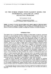
Fig. 4 F i -values calculated by the present method.<br />
τ<br />
σ<br />
xy0,<br />
FEM<br />
y0,<br />
FEM<br />
F i<br />
= +<br />
* τ<br />
≠<br />
* σ<br />
2 2<br />
F 1<br />
F2<br />
xy0,<br />
FEM<br />
y0,<br />
FEM<br />
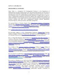
Table 1 Normalized stress intensity factors <strong>of</strong> Fig.1.<br />
(ν 1 =ν 2 =0.3, Plane stress)<br />
G 2 /G 1<br />
4.0<br />
10.0<br />
a/w<br />
F = K /( σ π ) F = K /( σ π )<br />
1 1 a<br />
2 2 a<br />
Present Ref.(5) Ref.(6) Present Ref.(5) Ref.(6)<br />
0.1 1.207 1.201 1.209 -0.240 -0.238 -0.238<br />
0.2 1.365 1.387 1.368 -0.251 -0.254 -0.250<br />
0.3 1.644 1.653 1.654 -0.286 -0.288 -0.288<br />
0.4 2.092 2.100 2.100 -0.359 -0.359 -0.358<br />
0.5 2.791 2.807 2.806 -0.484 -0.483 -0.483<br />
0.1 1.228 1.220 1.229 -0.341 -0.338 -0.338<br />
0.2 1.367 1.367 1.369 -0.350 -0.349 -0.348<br />
0.3 1.643 1.646 1.648 -0.400 -0.398 -0.398<br />
0.4 2.082 2.088 2.089 -0.495 -0.495 -0.493<br />
0.5 2.772 2.788 2.787 -0.663 -0.664 -0.661<br />
Fig.4 shows the stress intensity factor F i obtained by present method. The dimensionless value F i is<br />
defined by<br />
F i<br />
2 2 2 2<br />
= F + F = K + K /( σ π )<br />
(11)<br />
1 2 1 2<br />
a<br />
The exact value calculated by the body <strong>for</strong>ce method is 1.2752 [4] in this case. As shown in Fig.4,<br />
when the condition (6) is satisfied, values <strong>of</strong> F i obtained by present method are very close to 1.2752 at<br />
the crack tip node. However, F i –values have a large error near the crack tip when the condition (6) is<br />
not satisfied. There<strong>for</strong>e, in an interface crack problem, the stress value at the crack tip node is very<br />
effective as a measure <strong>of</strong> the strength <strong>of</strong> singular stress field, as well as a ordinary crack problem in<br />
homogeneous material [3].<br />
Table 1 shows the normalized stress intensity factors <strong>of</strong> the single edge interface crack problem, as<br />
shown in Fig.2. The results are compared with other results analyzed by the boundary element method<br />
[5, 6]. The analyses are per<strong>for</strong>med by changing the ratio <strong>of</strong> shear modulus G 2 /G 1 and the relative crack<br />
length a/w. As seen from Table 1, the present results coincide with other results. There<strong>for</strong>e, it can be<br />
said that the present method using FEM has sufficient accuracy in the case <strong>of</strong> interface crack problem.<br />
References<br />
[1] S.N. Atluri: Structural Integrity and Durability, Tech Science Press, Forsyth, GA (1997)<br />
[2] H. Kisu, R. Yuuki and H. Kitagawa: Transactions <strong>of</strong> the Japan Society <strong>of</strong> Mechanical Engineers<br />
(in Japanese), Vol. 51-463, Series A (1985), p. 660<br />
[3] H. Nisitani, T. Kawashima, W. Fujisaki and T. Fukuda: Transactions <strong>of</strong> the Japan Society <strong>of</strong><br />
Mechanical Engineers (in Japanese), Vol. 65-629, Series A (1999), p. 26<br />
[4] H. Nisitani and T. Teranishi: Key Engineering Materials, Vol. 243-244, (2003), p. 387<br />
[5] R. Yuuki and S.B. Cho: Engineering Fracture Mechanics, Vol. 34, (1989), p. 179<br />
[6] N. Miyazaki, T. Ikeda, T. Soda and T. Munakata: Engineering Fracture Mechanics, Vol. 45, No.5,<br />
(1993), p. 599
Progresses in Fracture and Strength <strong>of</strong> Materials and Structures<br />
10.4028/www.scientific.net/KEM.353-358<br />
<strong>Accurate</strong> <strong>Determination</strong> <strong>of</strong> <strong>Stress</strong> <strong>Intensity</strong> <strong>Factor</strong> <strong>for</strong> <strong>Interface</strong> <strong>Crack</strong> by Finite<br />
Element Method<br />
10.4028/www.scientific.net/KEM.353-358.3124