Create successful ePaper yourself
Turn your PDF publications into a flip-book with our unique Google optimized e-Paper software.
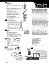
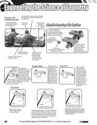
Engineering the Science of Geometry<br />
Anatomy of a<br />
CROWER ROCKER<br />
Our 2024 aluminum bodies<br />
deliver maximum strength at<br />
operating temperature.<br />
Our lash adjusters are machined from aircraft quality<br />
Hi-temp alloy, precision thread rolled after double<br />
heat treat process.<br />
Aircraft quality<br />
12 point nuts.<br />
Hardened tip wheel<br />
withstands race<br />
rigors and minimizes<br />
scrubbing.<br />
Needle Bearing Tip Option<br />
<strong>Crower</strong> has raised the bar<br />
on valve train technology with a<br />
new needle bearing roller tip option<br />
available on all new <strong>Crower</strong> stud and<br />
shaft mount rocker arm assemblies.<br />
Specify #73715R<br />
after rocker part number<br />
for stainless steel, #72915R<br />
for aluminum.<br />
Our Axles are “super secured” for<br />
trouble free operation.<br />
Fully rollerized precision<br />
needle bearing fulcrum.<br />
<strong>Crower</strong> shafts are CNC<br />
precision machined<br />
from ball race alloy<br />
steels, heat-treated<br />
twice and micro finish<br />
ground in-house.<br />
Reduced friction<br />
for added horsepower and reduced valve<br />
guide and valve stem wear.<br />
The lighter tip delivers<br />
greater valve control for<br />
increased rpm and improves<br />
valve spring longevity<br />
by decreasing heat over<br />
traditional non needle designs.<br />
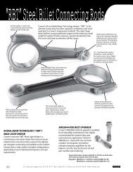
Ideal rocker<br />
geometry at<br />
half valve lift<br />
Highest unit loading<br />
on the valve train is approximately at<br />
half lift (45° @ cam lobe)<br />
90°<br />
90°<br />
Tip Travel<br />
This configuration<br />
minimizes tip travel across<br />
the valve stem and keeps<br />
contact centered on top<br />
of the valve, reducing<br />
frictional losses due to<br />
valve guide side loading<br />
and tip scrubbing. Pushrod<br />
deflection is also minimized<br />
for more accurate valve<br />
action.<br />
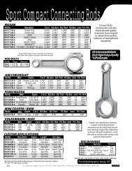
Rocker Ratio<br />
Rocker arm ratio is<br />
determined by dividing<br />
the distance from<br />
the fulcrum to the tip<br />
centerpoints (Y) by<br />
the distance from the<br />
fulcrum to the pushrod<br />
seat centerpoints (X).<br />
This theoretical ratio<br />
may vary from our net/<br />
advertised ratio due to<br />
measured valve train<br />
deflection under load.<br />
Long Arm<br />
Higher rocker ratios<br />
require extending the<br />
arm of the rocker. Long<br />
arm rockers allow proper<br />
pushrod seat positioning<br />
in relation to the fulcrum<br />
point. An additional long<br />
arm benefit is reduced<br />
back and forth tip travel<br />
across the valve stem. Less<br />
scrubbing and valve stem<br />
side loading occur and<br />
associated frictional losses<br />
are minimized.<br />
Less<br />
Than<br />
90°<br />
90°<br />
More<br />
Than<br />
90°<br />
Less<br />
Than<br />
90°<br />
90°<br />
More<br />
Than<br />
90°<br />
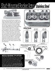
No Lift<br />
contact slightly behind centerline<br />
When the valve is closed tip<br />
contact is slightly behind the<br />
centerline of the valve.<br />
Half Lift<br />
centerline contact 1/2 lift<br />
At highest unit loading (approx. 1/2 lift) tip contact ideally is<br />
on the centerline of the valve. The valve train is overcoming<br />
spring pressure and, more importantly, rapidly accelerating<br />
its mass. To minimize deflection, side loading and frictional<br />
loss, we want the valve train geometry in its strongest and<br />
straightest configuration at this point.<br />
Full Lift<br />
contact slightly behind centerline<br />
When the valve is fully open, tip contact is slightly<br />
behind the centerline of the valve. The valve train in<br />
this position (at high RPM) feels the least amount of<br />
unit loading as float approaches...everything gets<br />
momentarily weightless.<br />
136 For technical support call 619-661-6477 or visit www.crower.com