7. Best Practices for the Quartus II TimeQuest Timing Analyzer
7. Best Practices for the Quartus II TimeQuest Timing Analyzer
7. Best Practices for the Quartus II TimeQuest Timing Analyzer

Create successful ePaper yourself
Turn your PDF publications into a flip-book with our unique Google optimized e-Paper software.
December 2010<br />
Q<strong>II</strong>53024-10.1.0<br />
Q<strong>II</strong>53024-10.1.0<br />
© 2010 Altera Corporation. All rights reserved. ALTERA, ARRIA, CYCLONE, HARDCOPY, MAX, MEGACORE, NIOS, QUARTUS and STRATIX are Reg. U.S. Pat. & Tm. Off.<br />
and/or trademarks of Altera Corporation in <strong>the</strong> U.S. and o<strong>the</strong>r countries. All o<strong>the</strong>r trademarks and service marks are <strong>the</strong> property of <strong>the</strong>ir respective holders as described at<br />
www.altera.com/common/legal.html. Altera warrants per<strong>for</strong>mance of its semiconductor products to current specifications in accordance with Altera’s standard warranty, but<br />
reserves <strong>the</strong> right to make changes to any products and services at any time without notice. Altera assumes no responsibility or liability arising out of <strong>the</strong> application or use of any<br />
in<strong>for</strong>mation, product, or service described herein except as expressly agreed to in writing by Altera. Altera customers are advised to obtain <strong>the</strong> latest version of device<br />
specifications be<strong>for</strong>e relying on any published in<strong>for</strong>mation and be<strong>for</strong>e placing orders <strong>for</strong> products or services.<br />
<strong>Quartus</strong> <strong>II</strong> Handbook Version 11.0 Volume 3: Verification<br />
December 2010<br />
<strong>7.</strong> <strong>Best</strong> <strong>Practices</strong> <strong>for</strong> <strong>the</strong> <strong>Quartus</strong> <strong>II</strong><br />
<strong>TimeQuest</strong> <strong>Timing</strong> <strong>Analyzer</strong><br />
<strong>Timing</strong> constraints and exceptions are vital to all designs that target FPGAs because<br />
<strong>the</strong>y allow designers to specify requirements and verify timing of <strong>the</strong>ir systems or<br />
FPGAs. Constraints and exceptions allow <strong>the</strong> Fitter to spend more time fitting <strong>the</strong><br />
critical paths in your design and reduce <strong>the</strong> amount of time spent on noncritical parts<br />
of <strong>the</strong> design.<br />
This chapter provides recommendations on how to fully constrain an FPGA design<br />
with <strong>the</strong> <strong>Quartus</strong> ® <strong>II</strong> <strong>TimeQuest</strong> <strong>Timing</strong> <strong>Analyzer</strong>. The sections are ordered in <strong>the</strong><br />
recommended flow <strong>for</strong> applying timing constraints and exceptions in <strong>the</strong> <strong>TimeQuest</strong><br />
analyzer.<br />
f For more in<strong>for</strong>mation about interactive timing analysis, refer to <strong>the</strong> <strong>TimeQuest</strong> <strong>Timing</strong><br />
<strong>Analyzer</strong> Quick Start Tutorial.<br />
f For more in<strong>for</strong>mation about Altera resources available <strong>for</strong> <strong>the</strong> <strong>TimeQuest</strong> analyzer,<br />
refer to <strong>the</strong> <strong>TimeQuest</strong> <strong>Timing</strong> <strong>Analyzer</strong> Resource Center of <strong>the</strong> Altera website.<br />
f For more in<strong>for</strong>mation about constraining circuits and reporting timing analysis<br />
results in <strong>the</strong> <strong>TimeQuest</strong> analyzer, including examples, refer to <strong>the</strong> <strong>TimeQuest</strong> Design<br />
Examples page of <strong>the</strong> Altera website and <strong>the</strong> <strong>Quartus</strong> <strong>II</strong> <strong>TimeQuest</strong> <strong>Timing</strong> <strong>Analyzer</strong><br />
Cookbook.<br />
f For more in<strong>for</strong>mation about constraints and exceptions supported by <strong>the</strong> <strong>TimeQuest</strong><br />
analyzer, refer to <strong>the</strong> <strong>Quartus</strong> <strong>II</strong> <strong>TimeQuest</strong> <strong>Timing</strong> <strong>Analyzer</strong> chapter in volume 3 of <strong>the</strong><br />
<strong>Quartus</strong> <strong>II</strong> Handbook.<br />
h For more in<strong>for</strong>mation about <strong>TimeQuest</strong> analyzer Tcl commands and a complete list of<br />
commands, refer to ::quartus::sta in <strong>Quartus</strong> <strong>II</strong> Help. For more in<strong>for</strong>mation about<br />
standard SDC commands and a complete list of commands, refer to ::quartus::sdc in<br />
<strong>Quartus</strong> <strong>II</strong> Help. For more in<strong>for</strong>mation about Altera extensions of SDC commands<br />
and a complete list of commands, refer to ::quartus::sdc_ext in <strong>Quartus</strong> <strong>II</strong> Help.<br />
This chapter contains <strong>the</strong> following sections:<br />
■ “Creating Clock Requirements” on page 7–2<br />
■ “Creating I/O Requirements” on page 7–5<br />
■ “Creating <strong>Timing</strong> Exceptions” on page 7–7<br />
Subscribe
7–2 Chapter 7: <strong>Best</strong> <strong>Practices</strong> <strong>for</strong> <strong>the</strong> <strong>Quartus</strong> <strong>II</strong> <strong>TimeQuest</strong> <strong>Timing</strong> <strong>Analyzer</strong><br />
Creating Clock Requirements<br />
Creating Clock Requirements<br />
The <strong>TimeQuest</strong> analyzer supports <strong>the</strong> following types of clocks:<br />
■ Base clocks<br />
■ Derived clocks<br />
■ Virtual clocks<br />
Clocks are used to specify register-to-register requirements <strong>for</strong> synchronous transfers<br />
and guide <strong>the</strong> Fitter optimization algorithms to achieve <strong>the</strong> best possible placement<br />
<strong>for</strong> your design.<br />
Specify clock constraints first in Synopsys Design Constraint Files (.sdc) because o<strong>the</strong>r<br />
constraints may reference previously defined clocks. The <strong>TimeQuest</strong> analyzer reads<br />
SDC constraints and exceptions from top to bottom in <strong>the</strong> file.<br />
f For more in<strong>for</strong>mation about creating clocks and clock constraints, refer to <strong>the</strong><br />
<strong>Quartus</strong> <strong>II</strong> <strong>TimeQuest</strong> <strong>Timing</strong> <strong>Analyzer</strong> chapter in volume 3 of <strong>the</strong> <strong>Quartus</strong> <strong>II</strong> Handbook.<br />
Base Clocks<br />
Base clocks are <strong>the</strong> primary input clocks to <strong>the</strong> FPGA. Unlike clocks from<br />
phase-locked loops (PLLs) that are derived within <strong>the</strong> FPGA, base clocks are usually<br />
generated in off-chip oscillators or <strong>for</strong>warded from an external device. Define base<br />
clocks first because derived clocks and o<strong>the</strong>r constraints can reference <strong>the</strong> base clocks.<br />
Use <strong>the</strong> create_clock command to constrain all primary input clocks. The target <strong>for</strong><br />
<strong>the</strong> create_clock command is usually an FPGA device pin. To specify <strong>the</strong> FPGA<br />
device pin as <strong>the</strong> target, use <strong>the</strong> get_ports command. Example 7–1 shows how to<br />
specify a 100-MHz requirement on a clk_sys input clock port.<br />
Example 7–1. create_clock Command<br />
create_clock -period 10 -name clk_sys [get_ports clk_sys]<br />
You can apply multiple clocks on <strong>the</strong> same clock node with <strong>the</strong> -add option.<br />
Example 7–2 shows how to specify that two oscillators drive <strong>the</strong> same clock port on<br />
<strong>the</strong> FPGA.<br />
Example 7–2. Two Oscillators Driving <strong>the</strong> Same Clock Port<br />
create_clock -period 10 -name clk_100 [get_ports clk_sys]<br />
create_clock -period 5 -name clk_200 [get_ports clk_sys] -add<br />
h For more in<strong>for</strong>mation about <strong>the</strong> create_clock and get_ports commands—including<br />
full syntax in<strong>for</strong>mation, options, and example usage—refer to create_clock and<br />
get_ports in <strong>Quartus</strong> <strong>II</strong> Help.<br />
<strong>Quartus</strong> <strong>II</strong> Handbook Version 11.0 Volume 3: Verification December 2010 Altera Corporation
Chapter 7: <strong>Best</strong> <strong>Practices</strong> <strong>for</strong> <strong>the</strong> <strong>Quartus</strong> <strong>II</strong> <strong>TimeQuest</strong> <strong>Timing</strong> <strong>Analyzer</strong> 7–3<br />
Creating Clock Requirements<br />
Derived Clocks<br />
Derived clocks are generated in <strong>the</strong> FPGA when you modify <strong>the</strong> properties, including<br />
phase, frequency, offset, and duty cycle, of a source clock signal. Derived clocks,<br />
which are PLLs or register clock dividers, are constrained after all base clocks are<br />
constrained in <strong>the</strong> .sdc. Derived clocks capture all clock delays and clock latency<br />
where <strong>the</strong> derived clock target is defined, ensuring that all base clock properties are<br />
accounted <strong>for</strong> in <strong>the</strong> derived clock.<br />
You can use <strong>the</strong> create_generated_clock command to constrain all generated clocks<br />
in your design. The source of <strong>the</strong> create_generated_clock command should be a<br />
node in your design and not a previously constrained clock.<br />
Example 7–3 shows a divide-by-two clock divider.<br />
Use <strong>the</strong> create_generated_clock command with <strong>the</strong> -source option when you<br />
specify multiple clock constraints <strong>for</strong> <strong>the</strong> same pin in a design. When you use <strong>the</strong><br />
create_generated_clock command, <strong>the</strong> -source option should refer to <strong>the</strong> nearest<br />
clock pin of <strong>the</strong> specified target. Do not use <strong>the</strong> clock port as <strong>the</strong> source <strong>for</strong> a generated<br />
clock, because multiple source clocks can feed <strong>the</strong> clock port. In Example 7–3, <strong>the</strong><br />
-source option assigns <strong>the</strong> clock pin of <strong>the</strong> register as <strong>the</strong> source <strong>for</strong> <strong>the</strong> generated<br />
clock instead of <strong>the</strong> clock port clk feeding <strong>the</strong> register’s reg clock pin.<br />
The <strong>TimeQuest</strong> analyzer provides <strong>the</strong> derive_pll_clocks command to automatically<br />
generate derived clocks <strong>for</strong> all PLL clock outputs. The properties of <strong>the</strong> generated<br />
clocks on <strong>the</strong> PLL outputs match <strong>the</strong> properties defined <strong>for</strong> <strong>the</strong> PLL.<br />
h For more in<strong>for</strong>mation about <strong>the</strong> create_generated_clock and derive_pll_clocks<br />
commands—including <strong>for</strong> full syntax in<strong>for</strong>mation, options, and example usage—refer<br />
to create_generate_clock and derive_pll_clocks in <strong>Quartus</strong> <strong>II</strong> Help.<br />
Virtual Clocks<br />
Example 7–3. Clock Divider<br />
create_clock -period 10 -name clk_sys [get_ports clk_sys]<br />
create_generated_clock -name clk_div_2 -divide_by 2 -source<br />
[get_pins reg|clk] [get_pins reg|regout]<br />
A virtual clock does not have a real source in your design and does not interact<br />
directly with your design. You can create virtual clocks with <strong>the</strong> create_clock<br />
command, with no targets specified. Example 7–4 shows how to create a 10 ns virtual<br />
clock.<br />
Example 7–4. Create Virtual Clock<br />
create_clock -period 10 -name my_virt_clk<br />
If you use <strong>the</strong> derive_clock_uncertainty command <strong>for</strong> your design, use virtual<br />
clocks with <strong>the</strong> set_input_delay and set_output_delay commands. It is important to<br />
use virtual clocks to allow <strong>the</strong> <strong>TimeQuest</strong> analyzer to calculate clock uncertainty<br />
separately <strong>for</strong> I/O interfaces and internal register-to-register paths.<br />
December 2010 Altera Corporation <strong>Quartus</strong> <strong>II</strong> Handbook Version 11.0 Volume 3: Verification
7–4 Chapter 7: <strong>Best</strong> <strong>Practices</strong> <strong>for</strong> <strong>the</strong> <strong>Quartus</strong> <strong>II</strong> <strong>TimeQuest</strong> <strong>Timing</strong> <strong>Analyzer</strong><br />
Creating Clock Requirements<br />
If an FPGA interfaces with an external device, and both <strong>the</strong> FPGA and external device<br />
have different clock sources, you should model <strong>the</strong> clock source <strong>for</strong> <strong>the</strong> external<br />
device with a virtual clock.<br />
h For more in<strong>for</strong>mation about <strong>the</strong> set_input_delay, set_output_delay, and<br />
derive_clock_uncertainty commands—including full syntax in<strong>for</strong>mation, options,<br />
and example usage—refer to set_input_delay, set_output_delay, and<br />
derive_clock_uncertainty in <strong>Quartus</strong> <strong>II</strong> Help.<br />
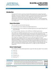
Figure 7–1 shows a typical I/O interface that contains an FPGA that interfaces with an<br />
external device and also shows a virtual clock. Example 7–5 shows how to create an<br />
equivalent virtual clock <strong>for</strong> each clock in your design that feeds an input or output<br />
port.<br />
Figure 7–1. Design with Virtual Clock<br />
External Device<br />
Altera FPGA<br />
data_in<br />
D reg1 Q D reg1 Q<br />
Example 7–5. Commands to Create Clocks<br />
100 MHz<br />
# Create <strong>the</strong> base clock <strong>for</strong> <strong>the</strong> clock port<br />
create_clock –period 10 –name clk_in [get_ports clk_in]<br />
# Create a virtual clock with <strong>the</strong> same properties of <strong>the</strong> base clock<br />
# driving <strong>the</strong> source register<br />
create_clock –period 10 –name virt_clk_in<br />
# Create <strong>the</strong> input delay referencing <strong>the</strong> virtual clock and not <strong>the</strong> base<br />
# clock<br />
# DO NOT use set_input_delay –clock clk_in <br />
# [get_ports data_in]<br />
set_input_delay –clock virt_clk_in [get_ports data_in]<br />
<strong>Quartus</strong> <strong>II</strong> Handbook Version 11.0 Volume 3: Verification December 2010 Altera Corporation<br />
clk_in
Chapter 7: <strong>Best</strong> <strong>Practices</strong> <strong>for</strong> <strong>the</strong> <strong>Quartus</strong> <strong>II</strong> <strong>TimeQuest</strong> <strong>Timing</strong> <strong>Analyzer</strong> 7–5<br />
Creating I/O Requirements<br />
Creating I/O Requirements<br />
Figure 7–2 shows a design that contains an FPGA that interfaces with an external<br />
device and also shows <strong>the</strong> base clock and <strong>the</strong> virtual clock. Example 7–6 shows how to<br />
create virtual clock <strong>for</strong> <strong>the</strong> design.<br />
Figure 7–2. Design with Base Clock and Virtual Clock<br />
External Device<br />
Example 7–6. Commands to Create Clocks<br />
D<br />
reg1<br />
data_out<br />
data_in<br />
Altera FPGA<br />
Q D Q<br />
50 MHz 100 MHz<br />
#create base clock <strong>for</strong> <strong>the</strong> design<br />
create_clock -period 10 -name clk_in [get_ports clk_in]<br />
#create <strong>the</strong> virtual clock <strong>for</strong> <strong>the</strong> external register<br />
create_clock -period 20 -name virt_clk -wave<strong>for</strong>m {0 10}<br />
#set <strong>the</strong> output delay referencing <strong>the</strong> virtual clock<br />
set_output_delay -clock virt_clk -max 1.5 [get_ports data_out]<br />
You should specify timing requirements, including internal and external timing<br />
requirements, be<strong>for</strong>e you fully analyze a design. With external timing requirements<br />
specified, <strong>the</strong> <strong>TimeQuest</strong> analyzer verifies <strong>the</strong> I/O interface, or periphery of <strong>the</strong><br />
FPGA, against any system specification. The <strong>TimeQuest</strong> analyzer supports input and<br />
output external delay modeling.<br />
You should specify I/O requirements after you constrain all clocks in your design.<br />
When specifying I/O requirements, reference a virtual clock in <strong>the</strong> constraints.<br />
f For more in<strong>for</strong>mation about specifying I/O interface requirements and uncertainty,<br />
refer to <strong>the</strong> <strong>Quartus</strong> <strong>II</strong> <strong>TimeQuest</strong> <strong>Timing</strong> <strong>Analyzer</strong> chapter in volume 3 of <strong>the</strong> <strong>Quartus</strong> <strong>II</strong><br />
Handbook.<br />
December 2010 Altera Corporation <strong>Quartus</strong> <strong>II</strong> Handbook Version 11.0 Volume 3: Verification<br />
clk_in<br />
Virtual Clock Base Clock<br />
reg1
7–6 Chapter 7: <strong>Best</strong> <strong>Practices</strong> <strong>for</strong> <strong>the</strong> <strong>Quartus</strong> <strong>II</strong> <strong>TimeQuest</strong> <strong>Timing</strong> <strong>Analyzer</strong><br />
Creating I/O Requirements<br />
Input Constraints<br />
Input constraints allow you to specify all <strong>the</strong> external delays feeding into <strong>the</strong> FPGA.<br />
Specify input requirements <strong>for</strong> all input ports in your design.<br />
You can use <strong>the</strong> set_input_delay command to specify external input delay<br />
requirements. Use <strong>the</strong> -clock option to reference a virtual clock. Using a virtual clock<br />
allows <strong>the</strong> <strong>TimeQuest</strong> analyzer to correctly derive clock uncertainties <strong>for</strong> interclock<br />
and intraclock transfers. The virtual clock defines <strong>the</strong> launching clock <strong>for</strong> <strong>the</strong> input<br />
port. The <strong>TimeQuest</strong> analyzer automatically determines <strong>the</strong> latching clock inside <strong>the</strong><br />
device that captures <strong>the</strong> input data, because all clocks in <strong>the</strong> device are defined.<br />
Figure 7–3 shows an example of an input delay referencing a virtual clock.<br />
Figure 7–3. Input Delay<br />
Equation 7–1 shows a typical input delay calculation.<br />
Equation 7–1. Input Delay Calculation<br />
Output Constraints<br />
External Device<br />
tco_ext<br />
cd_ext<br />
Oscillator<br />
Altera Device<br />
Output constraints allow you to specify all external delays from <strong>the</strong> FPGA <strong>for</strong> all<br />
output ports in your design.<br />
You can use <strong>the</strong> set_output_delay command to specify external output delay<br />
requirements. Use <strong>the</strong> -clock option to reference a virtual clock. The virtual clock<br />
defines <strong>the</strong> latching clock <strong>for</strong> <strong>the</strong> output port. The <strong>TimeQuest</strong> analyzer automatically<br />
determines <strong>the</strong> launching clock inside <strong>the</strong> device that launches <strong>the</strong> output data,<br />
because all clocks in <strong>the</strong> device are defined. Figure 7–4 shows an example of an output<br />
delay referencing a virtual clock.<br />
<strong>Quartus</strong> <strong>II</strong> Handbook Version 11.0 Volume 3: Verification December 2010 Altera Corporation<br />
dd<br />
cd_altr<br />
input delayMAX = �cd_extMIN – cd_altrMAX�+ tco_extMAX + ddMAX input delayMIN = �cd_extMAX – cd_altrMIN�+ tco_extMIN + ddMIN Figure 7–4. Output Delay<br />
Altera Device<br />
cd_altr<br />
Oscillator<br />
dd<br />
cd_ext<br />
External Device<br />
tsu_ext/th_ext
Chapter 7: <strong>Best</strong> <strong>Practices</strong> <strong>for</strong> <strong>the</strong> <strong>Quartus</strong> <strong>II</strong> <strong>TimeQuest</strong> <strong>Timing</strong> <strong>Analyzer</strong> 7–7<br />
Creating <strong>Timing</strong> Exceptions<br />
Equation 7–2 shows a typical output delay calculation.<br />
h For more in<strong>for</strong>mation about <strong>the</strong> set_input_delay and set_output_delay<br />
commands—including full syntax in<strong>for</strong>mation, options, and example usage—refer to<br />
set_input_delay and set_output_delay in <strong>Quartus</strong> <strong>II</strong> Help.<br />
Creating <strong>Timing</strong> Exceptions<br />
<strong>Timing</strong> exceptions in <strong>the</strong> <strong>TimeQuest</strong> analyzer provide a way to modify <strong>the</strong> default<br />
timing analysis behavior to match <strong>the</strong> analysis required by your design. Specify<br />
timing exceptions after clocks and input and output delay constraints because timing<br />
exceptions can modify <strong>the</strong> default analysis. The <strong>TimeQuest</strong> analyzer supports <strong>the</strong><br />
following three major categories of timing exceptions:<br />
■ False paths<br />
■ Minimum and maximum delays<br />
■ Multicycle paths<br />
f For more in<strong>for</strong>mation about creating timing exceptions, refer to <strong>the</strong> <strong>Quartus</strong> <strong>II</strong><br />
<strong>TimeQuest</strong> <strong>Timing</strong> <strong>Analyzer</strong> chapter in volume 3 of <strong>the</strong> <strong>Quartus</strong> <strong>II</strong> Handbook.<br />
False Paths<br />
Equation 7–2. output Delay Calculation<br />
input delayMAX = ddMAX – tsu_ext + �cd_altrMIN – cd_extMAX� input delayMIN = ddMIN – th_ext + �cd_altrMAX – cd_extMIN� Specifying a false path in your design removes <strong>the</strong> path from timing analysis. Use <strong>the</strong><br />
set_false_path command to specify false paths in your design. You can specify<br />
ei<strong>the</strong>r a point-to-point or clock-to-clock path as a false path. For example, a path you<br />
should specify as false path is a static configuration register that is written once<br />
during power-up initialization, but does not change state again. Although signals<br />
from static configuration registers often cross clock domains, you may not want to<br />
make false path exceptions to a clock-to-clock path, because some data may transfer<br />
across clock domains. However, you can selectively make false path exceptions from<br />
<strong>the</strong> static configuration register to all endpoints.<br />
Example 7–7 shows how to make false path exceptions from all registers beginning<br />
with A to all registers beginning with B.<br />
Example 7–<strong>7.</strong> False Path<br />
set_false_path -from [get_pins A*] -to [get_pins B*]<br />
The <strong>TimeQuest</strong> analyzer assumes all clocks are related unless you specify o<strong>the</strong>rwise.<br />
You can use clock groups to make false path exceptions <strong>for</strong> clock-to-clock timing<br />
relationships in your design. Clock groups are a more efficient way to make false path<br />
exceptions between clocks, compared to writing multiple set_false_path exceptions<br />
between every clock transfer you want to eliminate.<br />
December 2010 Altera Corporation <strong>Quartus</strong> <strong>II</strong> Handbook Version 11.0 Volume 3: Verification
7–8 Chapter 7: <strong>Best</strong> <strong>Practices</strong> <strong>for</strong> <strong>the</strong> <strong>Quartus</strong> <strong>II</strong> <strong>TimeQuest</strong> <strong>Timing</strong> <strong>Analyzer</strong><br />
Creating Multicycle Exceptions<br />
1 The <strong>TimeQuest</strong> analyzer runs more efficiently with clock groups ra<strong>the</strong>r than<br />
individual false path assignments.<br />
Use <strong>the</strong> set_clock_groups command to collect groups of signals related to each o<strong>the</strong>r,<br />
and use <strong>the</strong> -asynchronous option to specify that each group of clocks is<br />
asynchronous with each o<strong>the</strong>r. If you apply multiple clocks to <strong>the</strong> same port, use <strong>the</strong><br />
set_clock_groups command with <strong>the</strong> -exclusive option to place <strong>the</strong> clocks into<br />
separate groups and declare that <strong>the</strong> clocks are mutually exclusive. The clocks cannot<br />
physically exist in your design at <strong>the</strong> same time.<br />
h For more in<strong>for</strong>mation about <strong>the</strong> set_clock_groups and set_false_path commands—<br />
including full syntax in<strong>for</strong>mation, options, and example usage—refer to<br />
set_clock_groups and set_false_path in <strong>Quartus</strong> <strong>II</strong> Help.<br />
Minimum and Maximum Delays<br />
Specifying minimum and maximum delay constraints in your design creates a<br />
bounded minimum and maximum path delay. Use <strong>the</strong> set_min_delay and<br />
set_max_delay commands to create constraints <strong>for</strong> asynchronous signals that do not<br />
have a specific clock relationship in your design, but require a minimum and<br />
maximum path delay. You can create minimum and maximum delay exceptions <strong>for</strong><br />
port-to-port paths through <strong>the</strong> FPGA without a register stage in <strong>the</strong> path. If you use<br />
minimum and maximum delay exceptions to constrain <strong>the</strong> path delay, specify both<br />
<strong>the</strong> minimum and maximum delay of <strong>the</strong> path; do not constrain only <strong>the</strong> minimum or<br />
maximum value.<br />
You can also use <strong>the</strong> set_net_delay command to specify <strong>the</strong> minimum delay,<br />
maximum delay, or skew <strong>for</strong> any edge in your design when no clock relationships are<br />
defined or required.<br />
h For more in<strong>for</strong>mation about <strong>the</strong> set_min_delay, set_max_delay, and set_net_delay<br />
commands—including full syntax in<strong>for</strong>mation, options, and example usage—refer to<br />
set_min_delay, set_max_delay, and set_net_delay in <strong>Quartus</strong> <strong>II</strong> Help.<br />
Creating Multicycle Exceptions<br />
By default, <strong>the</strong> <strong>TimeQuest</strong> analyzer uses single-cycle path analysis. The <strong>TimeQuest</strong><br />
<strong>Timing</strong> <strong>Analyzer</strong> examines all register-to-register paths and per<strong>for</strong>ms setup and hold<br />
check analysis on those paths. The setup and hold check analysis evaluates <strong>the</strong> launch<br />
and latch edge relationships. When analyzing a path, <strong>the</strong> <strong>TimeQuest</strong> analyzer<br />
determines <strong>the</strong> setup launch and latch edge times by finding <strong>the</strong> closest two active<br />
edges in <strong>the</strong> respective wave<strong>for</strong>ms. When analyzing setup and hold relationships, <strong>the</strong><br />
<strong>TimeQuest</strong> analyzer analyzes <strong>the</strong> path against two timing conditions <strong>for</strong> every<br />
possible setup relationship, not just <strong>the</strong> worst-case setup relationship; <strong>the</strong>re<strong>for</strong>e, <strong>the</strong><br />
hold launch and latch times may be unrelated to <strong>the</strong> setup launch and latch edges.<br />
The <strong>TimeQuest</strong> analyzer does not report negative setup or hold relationships. When<br />
ei<strong>the</strong>r a negative setup or a negative hold relationship is calculated, <strong>the</strong> <strong>TimeQuest</strong><br />
analyzer moves both <strong>the</strong> launch and latch edges such that <strong>the</strong> setup and hold<br />
relationship becomes positive.<br />
<strong>Quartus</strong> <strong>II</strong> Handbook Version 11.0 Volume 3: Verification December 2010 Altera Corporation
Chapter 7: <strong>Best</strong> <strong>Practices</strong> <strong>for</strong> <strong>the</strong> <strong>Quartus</strong> <strong>II</strong> <strong>TimeQuest</strong> <strong>Timing</strong> <strong>Analyzer</strong> 7–9<br />
Creating Multicycle Exceptions<br />
Multicycle exceptions relax <strong>the</strong> timing requirements <strong>for</strong> a register-to-register path,<br />
allowing <strong>the</strong> Fitter to optimally place and route a design in an FPGA. Multicycle<br />
exceptions also can reduce compilation time and increase <strong>the</strong> quality of results.<br />
For example, if your design contains a long combinational path in which <strong>the</strong> latching<br />
register does not require data stability on every clock edge, but only on every second<br />
clock edge, you can assign a multicycle exception to <strong>the</strong> path. The multicycle path is<br />
dependent on <strong>the</strong> endpoint register’s use of <strong>the</strong> clock signal. Example 7–8 shows how<br />
to create a multicycle path <strong>for</strong> <strong>the</strong> combinational path where <strong>the</strong> data is stable at <strong>the</strong><br />
endpoint every two clock cycles of <strong>the</strong> endpoint latch clock.<br />
Example 7–8. Multicycle Path<br />
set_multicycle_path -setup 2<br />
If you specify a multicycle path, define both <strong>the</strong> setup and hold multicycle<br />
relationships. For <strong>the</strong> preceding example, setting data at <strong>the</strong> endpoint can take two<br />
clock cycles and <strong>the</strong> minimum hold time relationship is defined with a multicycle<br />
exception as well. Use <strong>the</strong> set_multicycle_path command with <strong>the</strong> -hold option to<br />
define <strong>the</strong> hold relationship. The value of <strong>the</strong> -hold option is (N – 1), where N is equal<br />
to <strong>the</strong> multicycle setup assignment value <strong>for</strong> a register-to-register path in <strong>the</strong> same<br />
clock domain. However, if data crosses different clock domains, <strong>the</strong> phase and period<br />
of <strong>the</strong> launch and latch clock may change <strong>the</strong> default multicycle setup and hold<br />
values. If you use multicycle paths that cross different clock domains, you must<br />
carefully examine <strong>the</strong> timing paths in <strong>the</strong> <strong>TimeQuest</strong> analyzer be<strong>for</strong>e and after<br />
applying <strong>the</strong> multicycle exception to determine if <strong>the</strong> launch and latch clock edges<br />
function as you intend.<br />
h For more in<strong>for</strong>mation about <strong>the</strong> set_multicycle_path command, including full<br />
syntax in<strong>for</strong>mation, options, and example usage, refer to set_multicycle_path in<br />
<strong>Quartus</strong> <strong>II</strong> Help.<br />
Multicycle Clock Setup Check and Hold Check Analysis<br />
You can modify <strong>the</strong> setup and hold relationship when you apply a multicycle<br />
exception to a register-to-register path. Figure 7–5 shows a register-to-register path<br />
with various timing parameters labeled.<br />
Figure 7–5. Register-to-Register Path<br />
CLK<br />
T clk1<br />
REG1 REG2<br />
SET Combinational<br />
SET<br />
D Q D Q<br />
Logic<br />
CLR CLR<br />
TCO Tclk2 T / T SU H<br />
December 2010 Altera Corporation <strong>Quartus</strong> <strong>II</strong> Handbook Version 11.0 Volume 3: Verification<br />
T data
7–10 Chapter 7: <strong>Best</strong> <strong>Practices</strong> <strong>for</strong> <strong>the</strong> <strong>Quartus</strong> <strong>II</strong> <strong>TimeQuest</strong> <strong>Timing</strong> <strong>Analyzer</strong><br />
Creating Multicycle Exceptions<br />
Multicycle constraints adjust setup or hold relationships by <strong>the</strong> specified number of<br />
clock cycles based on <strong>the</strong> source (-start) or destination (-end) clock. An end<br />
multicycle setup constraint of two extends <strong>the</strong> worst-case setup latch edge by one<br />
destination clock period.<br />
Hold multicycle constraints are based on <strong>the</strong> hold position—<strong>the</strong> default hold position<br />
is zero. An end multicycle hold constraint of one effectively subtracts one destination<br />
clock period from <strong>the</strong> default hold latch edge.<br />
To specify <strong>the</strong> multicycle constraints in your design, use <strong>the</strong> set_multicycle_path<br />
command.<br />
h For more in<strong>for</strong>mation about <strong>the</strong> set_multicycle_path command, including full<br />
syntax in<strong>for</strong>mation, options, and example usage, refer to set_multicycle_path in<br />
<strong>Quartus</strong> <strong>II</strong> Help.<br />
Table 7–1. Common Multicycle Assignments<br />
If you specify a multicycle constraint between timing nodes, <strong>the</strong> multicycle constraint<br />
applies only to <strong>the</strong> path between <strong>the</strong> two nodes. If you specify a multicycle constraint<br />
<strong>for</strong> a clock, <strong>the</strong> multicycle constraint applies to all paths where <strong>the</strong> source node<br />
(-from) or destination node (-to) is clocked by <strong>the</strong> clock.<br />
Table 7–1 summarizes commonly used multicycle assignments.<br />
Type Clock <strong>Timing</strong> Check SDC Command<br />
End Multicycle Setup Destination Setup<br />
End Multicycle Hold Destination Hold<br />
Start Multicycle Setup Source Setup<br />
Start Multicycle Hold Source Hold<br />
Multicycle Clock Setup<br />
set_multicycle_path<br />
–end –setup<br />
set_multicycle_path<br />
–end –hold<br />
set_multicycle_path<br />
–start –setup<br />
set_multicycle_path<br />
–start -hold<br />
The setup relationship is defined as <strong>the</strong> number of clock periods between <strong>the</strong> latch<br />
edge and <strong>the</strong> launch edge. By default, <strong>the</strong> <strong>TimeQuest</strong> analyzer per<strong>for</strong>ms a single-cycle<br />
path analysis, which results in <strong>the</strong> setup relationship being equal to one clock period<br />
(latch edge – launch edge). When analyzing a path, <strong>the</strong> <strong>TimeQuest</strong> analyzer<br />
determines <strong>the</strong> setup launch and latch edge times by finding <strong>the</strong> closest two active<br />
edges in <strong>the</strong> respective wave<strong>for</strong>ms. Applying a multicycle setup assignment,<br />
increases—or relaxes—<strong>the</strong> setup relationship by <strong>the</strong> multicycle setup value.<br />
<strong>Quartus</strong> <strong>II</strong> Handbook Version 11.0 Volume 3: Verification December 2010 Altera Corporation
Chapter 7: <strong>Best</strong> <strong>Practices</strong> <strong>for</strong> <strong>the</strong> <strong>Quartus</strong> <strong>II</strong> <strong>TimeQuest</strong> <strong>Timing</strong> <strong>Analyzer</strong> 7–11<br />
Creating Multicycle Exceptions<br />
Figure 7–6. End Multicycle Setup Values<br />
For every register-to-register path, <strong>the</strong> <strong>TimeQuest</strong> analyzer calculates <strong>the</strong> setup slack<br />
<strong>for</strong> <strong>the</strong> path. Equation 7–3 shows <strong>the</strong> setup slack calculation.<br />
Equation 7–3. Setup Slack (1) (2) (3) (4) (5) (6)<br />
setup slack = data required time – data arrival time<br />
= �latch edge + tclk2 – tSU�– �launch edge + tclk1 + tCO + tdata� = �latch edge – launch edge�+<br />
�tclk2 – tclk1�– �tCO + tdata + tSU� Notes to Equation 7–3:<br />
(1) tclk1 = <strong>the</strong> propagation delay from clock source to clock input on source register<br />
(2) tclk2 = <strong>the</strong> propagation delay from clock source to clock input on destination register<br />
(3) tdata = <strong>the</strong> propagation delay from source register to data input on destination register<br />
(4) tCO = <strong>the</strong> clock to output delay of source register<br />
(5) tSU = <strong>the</strong> setup requirement of destination register<br />
(6) tH = <strong>the</strong> hold requirement of destination register<br />
An end multicycle setup assignment modifies <strong>the</strong> latch edge of <strong>the</strong> destination clock<br />
by moving <strong>the</strong> latch edge <strong>the</strong> specified number of clock periods to <strong>the</strong> right of <strong>the</strong><br />
determined default latch edge. Figure 7–6 shows various values of <strong>the</strong> end multicycle<br />
setup assignment and <strong>the</strong> resulting latch edge.<br />
REG1.CLK<br />
REG2.CLK<br />
-10 0 10 20<br />
EMS = 1<br />
(default)<br />
December 2010 Altera Corporation <strong>Quartus</strong> <strong>II</strong> Handbook Version 11.0 Volume 3: Verification<br />
EMS = 2<br />
EMS = 3
7–12 Chapter 7: <strong>Best</strong> <strong>Practices</strong> <strong>for</strong> <strong>the</strong> <strong>Quartus</strong> <strong>II</strong> <strong>TimeQuest</strong> <strong>Timing</strong> <strong>Analyzer</strong><br />
Creating Multicycle Exceptions<br />
Figure 7–<strong>7.</strong> Start Multicycle Setup Values<br />
Source Clock<br />
Destination Clock<br />
A start multicycle setup assignment modifies <strong>the</strong> launch edge of <strong>the</strong> source clock by<br />
moving <strong>the</strong> launch edge <strong>the</strong> specified number of clock periods to <strong>the</strong> left of <strong>the</strong><br />
determined default launch edge. Figure 7–7 shows various values of <strong>the</strong> start<br />
multicycle setup assignment and <strong>the</strong> resulting launch edge.<br />
-20 -10<br />
0 10 20<br />
SMS = 3<br />
SMS = 2<br />
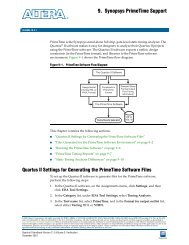
Figure 7–8 shows <strong>the</strong> setup relationship reported by <strong>the</strong> <strong>TimeQuest</strong> analyzer <strong>for</strong> <strong>the</strong><br />
negative setup relationship shown in Figure 7–<strong>7.</strong><br />
Multicycle Clock Hold<br />
SMS = 1<br />
(default)<br />
Figure 7–8. Start Multicycle Setup Values Reported by <strong>the</strong> <strong>TimeQuest</strong> <strong>Analyzer</strong><br />
Source Clock<br />
Destination Clock<br />
-10 0 10 20<br />
SMS = 1<br />
(default)<br />
The hold relationship is defined as <strong>the</strong> number of clock periods between <strong>the</strong> launch<br />
edge and <strong>the</strong> latch edge. By default, <strong>the</strong> <strong>TimeQuest</strong> analyzer per<strong>for</strong>ms a single-cycle<br />
path analysis, which results in <strong>the</strong> hold relationship being equal to one clock period<br />
(launch edge – latch edge). When analyzing a path, <strong>the</strong> <strong>TimeQuest</strong> analyzer per<strong>for</strong>ms<br />
two hold checks. The first hold check determines that <strong>the</strong> data launched by <strong>the</strong><br />
current launch edge is not captured by <strong>the</strong> previous latch edge. The second hold check<br />
determines that <strong>the</strong> data launched by <strong>the</strong> next launch edge is not captured by <strong>the</strong><br />
current latch edge. The <strong>TimeQuest</strong> analyzer reports only <strong>the</strong> most restrictive hold<br />
check. Equation 7–4 shows <strong>the</strong> calculation that <strong>the</strong> <strong>TimeQuest</strong> analyzer per<strong>for</strong>ms to<br />
determine <strong>the</strong> hold check.<br />
Equation 7–4. Hold Check<br />
<strong>Quartus</strong> <strong>II</strong> Handbook Version 11.0 Volume 3: Verification December 2010 Altera Corporation<br />
SMS = 2<br />
hold check 1 = current launch edge – previous latch edge<br />
hold check 2 =<br />
next launch edge – current latch edge<br />
SMS = 3
Chapter 7: <strong>Best</strong> <strong>Practices</strong> <strong>for</strong> <strong>the</strong> <strong>Quartus</strong> <strong>II</strong> <strong>TimeQuest</strong> <strong>Timing</strong> <strong>Analyzer</strong> 7–13<br />
Creating Multicycle Exceptions<br />
1 If a hold check overlaps a setup check, <strong>the</strong> hold check is ignored.<br />
Figure 7–9. Start Multicycle Hold Values<br />
Applying a multicycle hold assignment, increases—or relaxes—<strong>the</strong> hold slack<br />
equation by <strong>the</strong> number of specified clock cycles.<br />
For every register-to-register path, <strong>the</strong> <strong>TimeQuest</strong> analyzer calculates <strong>the</strong> hold slack<br />
<strong>for</strong> <strong>the</strong> path. Equation 7–5 shows <strong>the</strong> hold slack calculation.<br />
Equation 7–5. Hold Slack (1) (2) (3) (4) (5) (6)<br />
hold slack = data arrival time – data required time<br />
= �launch edge + tclk1 + tCO + tdata�– �latch edge + tclk2 – tH� = �launch edge – latch edge�–<br />
�tclk2 – tclk1�+ �tCO + tdata – tH� Notes to Equation 7–5:<br />
(1) tclk1 = <strong>the</strong> propagation delay from clock source to clock input on source register<br />
(2) tclk2 = <strong>the</strong> propagation delay from clock source to clock input on destination register<br />
(3) tdata = <strong>the</strong> propagation delay from source register to data input on destination register<br />
(4) tCO = <strong>the</strong> clock to output delay of source register<br />
(5) tSU = <strong>the</strong> setup requirement of destination register<br />
(6) tH = <strong>the</strong> hold requirement of destination register<br />
A start multicycle hold assignment modifies <strong>the</strong> launch edge of <strong>the</strong> destination clock<br />
by moving <strong>the</strong> latch edge <strong>the</strong> specified number of clock periods to <strong>the</strong> right of <strong>the</strong><br />
determined default launch edge. Figure 7–9 shows various values of <strong>the</strong> start<br />
multicycle hold assignment and <strong>the</strong> resulting launch edge.<br />
Source Clock<br />
Destination Clock<br />
-10 0 10 20<br />
SMH = 0<br />
(default)<br />
December 2010 Altera Corporation <strong>Quartus</strong> <strong>II</strong> Handbook Version 11.0 Volume 3: Verification<br />
SMH = 1<br />
SMH = 1
7–14 Chapter 7: <strong>Best</strong> <strong>Practices</strong> <strong>for</strong> <strong>the</strong> <strong>Quartus</strong> <strong>II</strong> <strong>TimeQuest</strong> <strong>Timing</strong> <strong>Analyzer</strong><br />
Creating Multicycle Exceptions<br />
Figure 7–10. End Multicycle Hold Values<br />
Source Clock<br />
Destination Clock<br />
An end multicycle hold assignment modifies <strong>the</strong> latch edge of <strong>the</strong> destination clock by<br />
moving <strong>the</strong> latch edge <strong>the</strong> specific ed number of clock periods to <strong>the</strong> left of <strong>the</strong><br />
determined default latch edge. Figure 7–10 shows various values of <strong>the</strong> end<br />
multicycle hold assignment and <strong>the</strong> resulting latch edge.<br />
-20 -10<br />
0 10 20<br />
EMH = 2<br />
EMH = 1<br />
Figure 7–11 shows <strong>the</strong> hold relationship reported by <strong>the</strong> <strong>TimeQuest</strong> analyzer <strong>for</strong> <strong>the</strong><br />
negative hold relationship shown in Figure 7–10.<br />
Examples of Basic Multicycle Exceptions<br />
This section describes <strong>the</strong> following examples of combinations of multicycle<br />
exceptions:<br />
■ “Default Settings” on page 7–15<br />
EMH= 0<br />
(default)<br />
Figure 7–11. End Multicycle Hold Values Reported by <strong>the</strong> <strong>TimeQuest</strong> <strong>Analyzer</strong><br />
Source Clock<br />
Destination Clock<br />
-10 0 10 20<br />
EMH = 0<br />
default)<br />
EMH = 2<br />
EMH = 1<br />
■ “End Multicycle Setup = 2 and End Multicycle Hold = 0” on page 7–17<br />
■ “End Multicycle Setup = 1 and End Multicycle Hold = 1” on page 7–20<br />
■ “End Multicycle Setup = 2 and End Multicycle Hold = 1” on page 7–23<br />
■ “Start Multicycle Setup = 2 and Start Multicycle Hold = 0” on page 7–26<br />
■ “Start Multicycle Setup = 1 and Start Multicycle Hold = 1” on page 7–29<br />
■ “Start Multicycle Setup = 2 and Start Multicycle Hold = 1” on page 7–32<br />
<strong>Quartus</strong> <strong>II</strong> Handbook Version 11.0 Volume 3: Verification December 2010 Altera Corporation
Chapter 7: <strong>Best</strong> <strong>Practices</strong> <strong>for</strong> <strong>the</strong> <strong>Quartus</strong> <strong>II</strong> <strong>TimeQuest</strong> <strong>Timing</strong> <strong>Analyzer</strong> 7–15<br />
Creating Multicycle Exceptions<br />
Each example explains how <strong>the</strong> multicycle exceptions affect <strong>the</strong> default setup and<br />
hold analysis in <strong>the</strong> <strong>TimeQuest</strong> analyzer. The multicycle exceptions are applied to a<br />
simple register-to-register circuit. Both <strong>the</strong> source and destination clocks are set to<br />
10 ns.<br />
Default Settings<br />
Figure 7–12. Default <strong>Timing</strong> Diagram<br />
By default, <strong>the</strong> <strong>TimeQuest</strong> analyzer per<strong>for</strong>ms a single-cycle analysis to determine <strong>the</strong><br />
setup and hold checks. Also, by default, <strong>the</strong> <strong>TimeQuest</strong> <strong>Timing</strong> <strong>Analyzer</strong> sets <strong>the</strong> end<br />
multicycle setup assignment value to one and <strong>the</strong> end multicycle hold assignment<br />
value to zero.<br />
Figure 7–12 shows <strong>the</strong> source and <strong>the</strong> destination timing wave<strong>for</strong>m <strong>for</strong> <strong>the</strong> source<br />
register and destination register, respectively.<br />
REG1.CLK<br />
REG2.CLK<br />
-10 0 10 20<br />
Current Launch<br />
HC1<br />
0 1 2<br />
Current Latch<br />
Equation 7–6 shows <strong>the</strong> calculation that <strong>the</strong> <strong>TimeQuest</strong> analyzer per<strong>for</strong>ms to<br />
determine <strong>the</strong> setup check.<br />
Equation 7–6. Setup Check<br />
setup check = current latch edge – closest previous launch edge<br />
= 10ns – 0ns<br />
= 10ns<br />
The most restrictive setup relationship with <strong>the</strong> default single-cycle analysis, that is, a<br />
setup relationship with an end multicycle setup assignment of one, is 10 ns.<br />
December 2010 Altera Corporation <strong>Quartus</strong> <strong>II</strong> Handbook Version 11.0 Volume 3: Verification<br />
SC<br />
HC2
7–16 Chapter 7: <strong>Best</strong> <strong>Practices</strong> <strong>for</strong> <strong>the</strong> <strong>Quartus</strong> <strong>II</strong> <strong>TimeQuest</strong> <strong>Timing</strong> <strong>Analyzer</strong><br />
Creating Multicycle Exceptions<br />
Figure 7–13. Setup Report<br />
Figure 7–13 shows <strong>the</strong> setup report <strong>for</strong> <strong>the</strong> default setup in <strong>the</strong> <strong>TimeQuest</strong> analyzer<br />
with <strong>the</strong> launch and latch edges highlighted.<br />
Equation 7–7 shows <strong>the</strong> calculation that <strong>the</strong> <strong>TimeQuest</strong> analyzer per<strong>for</strong>ms to<br />
determine <strong>the</strong> hold check. Both hold checks are equivalent.<br />
Equation 7–<strong>7.</strong> Hold Check<br />
hold check 1 = next launch edge – current latch edge<br />
= 0ns – 0ns<br />
= 0ns<br />
hold check 2 = 10 ns – 10 ns<br />
= 0 ns<br />
The most restrictive hold relationship with <strong>the</strong> default single-cycle analysis, that a<br />
hold relationship with an end multicycle hold assignment of zero, is 0 ns.<br />
<strong>Quartus</strong> <strong>II</strong> Handbook Version 11.0 Volume 3: Verification December 2010 Altera Corporation
Chapter 7: <strong>Best</strong> <strong>Practices</strong> <strong>for</strong> <strong>the</strong> <strong>Quartus</strong> <strong>II</strong> <strong>TimeQuest</strong> <strong>Timing</strong> <strong>Analyzer</strong> 7–17<br />
Creating Multicycle Exceptions<br />
Figure 7–14. Hold Report<br />
Figure 7–14 shows <strong>the</strong> hold report <strong>for</strong> <strong>the</strong> default setup in <strong>the</strong> <strong>TimeQuest</strong> analyzer<br />
with <strong>the</strong> launch and latch edges highlighted.<br />
End Multicycle Setup = 2 and End Multicycle Hold = 0<br />
In this example, <strong>the</strong> end multicycle setup assignment value is two, and <strong>the</strong> end<br />
multicycle hold assignment value is zero. Example 7–9 shows <strong>the</strong> multicycle<br />
exceptions applied to <strong>the</strong> register-to-register design <strong>for</strong> this example.<br />
Example 7–9. Multicycle Exceptions<br />
set_multicycle_path -from [get_clocks clk_src] -to [get_clocks clk_\<br />
dst] -setup -end 2<br />
1 An end multicycle hold value is not required because <strong>the</strong> default end multicycle hold<br />
value is zero.<br />
In this example, <strong>the</strong> setup relationship is relaxed by a full clock period by moving <strong>the</strong><br />
latch edge to <strong>the</strong> next latch edge. The hold analysis is unchanged from <strong>the</strong> default<br />
settings.<br />
December 2010 Altera Corporation <strong>Quartus</strong> <strong>II</strong> Handbook Version 11.0 Volume 3: Verification
7–18 Chapter 7: <strong>Best</strong> <strong>Practices</strong> <strong>for</strong> <strong>the</strong> <strong>Quartus</strong> <strong>II</strong> <strong>TimeQuest</strong> <strong>Timing</strong> <strong>Analyzer</strong><br />
Creating Multicycle Exceptions<br />
Figure 7–15. Setup <strong>Timing</strong> Diagram<br />
Figure 7–15 shows <strong>the</strong> setup timing diagram. The latch edge is a clock cycle later than<br />
in <strong>the</strong> default single-cycle analysis.<br />
REG1.CLK<br />
REG2.CLK<br />
Figure 7–16. Setup Report<br />
-10 0<br />
Current Launch<br />
10 20<br />
Current Latch<br />
Equation 7–8 shows <strong>the</strong> calculation that <strong>the</strong> <strong>TimeQuest</strong> analyzer per<strong>for</strong>ms to<br />
determine <strong>the</strong> setup check.<br />
Equation 7–8. Setup Check<br />
setup check = current latch edge – closest previous launch edge<br />
= 20 ns – 0 ns<br />
= 20 ns<br />
The most restrictive setup relationship with an end multicycle setup assignment of<br />
two is 20 ns.<br />
Figure 7–16 shows <strong>the</strong> setup report in <strong>the</strong> <strong>TimeQuest</strong> analyzer with <strong>the</strong> launch and<br />
latch edges highlighted.<br />
<strong>Quartus</strong> <strong>II</strong> Handbook Version 11.0 Volume 3: Verification December 2010 Altera Corporation<br />
SC
Chapter 7: <strong>Best</strong> <strong>Practices</strong> <strong>for</strong> <strong>the</strong> <strong>Quartus</strong> <strong>II</strong> <strong>TimeQuest</strong> <strong>Timing</strong> <strong>Analyzer</strong> 7–19<br />
Creating Multicycle Exceptions<br />
Figure 7–1<strong>7.</strong> Hold <strong>Timing</strong> DIagram<br />
Because <strong>the</strong> multicycle hold latch and launch edges are <strong>the</strong> same as <strong>the</strong> results of hold<br />
analysis with <strong>the</strong> default settings, <strong>the</strong> multicycle hold analysis in this example is<br />
equivalent to <strong>the</strong> single-cycle hold analysis. Figure 7–17 shows <strong>the</strong> timing diagram <strong>for</strong><br />
<strong>the</strong> hold checks <strong>for</strong> this example. The hold checks are relative to <strong>the</strong> setup check.<br />
Usually, <strong>the</strong> <strong>TimeQuest</strong> analyzer per<strong>for</strong>ms hold checks on every possible setup check,<br />
not only on <strong>the</strong> most restrictive setup check edges.<br />
REG1.CLK<br />
REG2.CLK<br />
-10 0<br />
Current Launch<br />
10 20<br />
Data HC1 SC<br />
HC2<br />
Current Latch<br />
Equation 7–9 shows <strong>the</strong> calculation that <strong>the</strong> <strong>TimeQuest</strong> analyzer per<strong>for</strong>ms to<br />
determine <strong>the</strong> hold check. Both hold checks are equivalent.<br />
Equation 7–9. Hold Check<br />
hold check 1 = current launch edge – previous latch edge<br />
= 0 ns – 10 ns<br />
= – 10 ns<br />
hold check 2 = next launch edge – current latch edge<br />
= 10 ns – 20 ns<br />
= –<br />
10 ns<br />
The most restrictive hold relationship with an end multicycle setup assignment value<br />
of two and an end multicycle hold assignment value of zero is 10 ns.<br />
December 2010 Altera Corporation <strong>Quartus</strong> <strong>II</strong> Handbook Version 11.0 Volume 3: Verification
7–20 Chapter 7: <strong>Best</strong> <strong>Practices</strong> <strong>for</strong> <strong>the</strong> <strong>Quartus</strong> <strong>II</strong> <strong>TimeQuest</strong> <strong>Timing</strong> <strong>Analyzer</strong><br />
Creating Multicycle Exceptions<br />
Figure 7–18. Hold Report<br />
Figure 7–18 shows <strong>the</strong> hold report <strong>for</strong> this example in <strong>the</strong> <strong>TimeQuest</strong> analyzer with<br />
<strong>the</strong> launch and latch edges highlighted.<br />
End Multicycle Setup = 1 and End Multicycle Hold = 1<br />
In this example, <strong>the</strong> end multicycle setup assignment value is one, and <strong>the</strong> end<br />
multicycle hold assignment value is one. Example 7–10 shows <strong>the</strong> multicycle<br />
exceptions applied to <strong>the</strong> register-to-register design <strong>for</strong> this example.<br />
Example 7–10. Multicycle Exceptions<br />
set_multicycle_path -from [get_clocks clk_src] -to [get_clocks clk_\<br />
dst] -hold -end 1<br />
1 An end multicycle setup value is not required because <strong>the</strong> default end multicycle<br />
setup value is one.<br />
In this example, <strong>the</strong> hold relationship is relaxed by one clock period by moving <strong>the</strong><br />
latch edge to <strong>the</strong> previous latch edge. The setup analysis is unchanged from <strong>the</strong><br />
default settings.<br />
<strong>Quartus</strong> <strong>II</strong> Handbook Version 11.0 Volume 3: Verification December 2010 Altera Corporation
Chapter 7: <strong>Best</strong> <strong>Practices</strong> <strong>for</strong> <strong>the</strong> <strong>Quartus</strong> <strong>II</strong> <strong>TimeQuest</strong> <strong>Timing</strong> <strong>Analyzer</strong> 7–21<br />
Creating Multicycle Exceptions<br />
Figure 7–19. Setup <strong>Timing</strong> Diagram<br />
Figure 7–19 shows <strong>the</strong> setup timing diagram. The latch edge is <strong>the</strong> same as <strong>the</strong> default<br />
single-cycle analysis.<br />
SRC.CLK<br />
DST.CLK<br />
-10 0<br />
Current<br />
Launch<br />
10 20<br />
HC1<br />
Equation 7–10 shows <strong>the</strong> calculation that <strong>the</strong> <strong>TimeQuest</strong> analyzer per<strong>for</strong>ms to<br />
determine <strong>the</strong> setup check.<br />
The most restrictive setup relationship with an end multicycle setup assignment of<br />
one is 10 ns.<br />
December 2010 Altera Corporation <strong>Quartus</strong> <strong>II</strong> Handbook Version 11.0 Volume 3: Verification<br />
SC<br />
HC2<br />
Current<br />
Latch<br />
Equation 7–10. Setup Check<br />
setup check = current latch edge – closest previous launch edge<br />
= 10 ns – 0 ns<br />
= 10 ns
7–22 Chapter 7: <strong>Best</strong> <strong>Practices</strong> <strong>for</strong> <strong>the</strong> <strong>Quartus</strong> <strong>II</strong> <strong>TimeQuest</strong> <strong>Timing</strong> <strong>Analyzer</strong><br />
Creating Multicycle Exceptions<br />
Figure 7–20. Setup Report<br />
Figure 7–21. Hold <strong>Timing</strong> Diagram<br />
Figure 7–20 shows <strong>the</strong> setup report in <strong>the</strong> <strong>TimeQuest</strong> analyzer with <strong>the</strong> launch and<br />
latch edges highlighted.<br />
Figure 7–21 shows <strong>the</strong> timing diagram <strong>for</strong> <strong>the</strong> hold checks <strong>for</strong> this example. The hold<br />
checks are relative to <strong>the</strong> setup check.<br />
SRC.CLK<br />
DST.CLK<br />
-10 0<br />
Current<br />
Launch<br />
10 20<br />
HC1<br />
<strong>Quartus</strong> <strong>II</strong> Handbook Version 11.0 Volume 3: Verification December 2010 Altera Corporation<br />
SC<br />
HC2<br />
Current<br />
Latch
Chapter 7: <strong>Best</strong> <strong>Practices</strong> <strong>for</strong> <strong>the</strong> <strong>Quartus</strong> <strong>II</strong> <strong>TimeQuest</strong> <strong>Timing</strong> <strong>Analyzer</strong> 7–23<br />
Creating Multicycle Exceptions<br />
Figure 7–22. Hold Report<br />
Equation 7–11 shows <strong>the</strong> calculation that <strong>the</strong> <strong>TimeQuest</strong> analyzer per<strong>for</strong>ms to<br />
determine <strong>the</strong> hold check. Both hold checks are equivalent.<br />
Equation 7–11. Hold Check<br />
hold check 1 = current launch edge – previous latch edge<br />
= 0 ns – �– 10 ns�<br />
= 10 ns<br />
hold check 2 = next launch edge – current latch edge<br />
= 10 ns – 0 ns<br />
= 10 ns<br />
The most restrictive hold relationship with an end multicycle setup assignment value<br />
of one and an end multicycle hold assignment value of one is 10 ns.<br />
Figure 7–22 shows <strong>the</strong> hold report <strong>for</strong> this example in <strong>the</strong> <strong>TimeQuest</strong> analyzer with<br />
<strong>the</strong> launch and latch edges highlighted.<br />
End Multicycle Setup = 2 and End Multicycle Hold = 1<br />
In this example, <strong>the</strong> end multicycle setup assignment value is two, and <strong>the</strong> end<br />
multicycle hold assignment value is one. Example 7–11 shows <strong>the</strong> multicycle<br />
exceptions applied to <strong>the</strong> register-to-register design <strong>for</strong> this example.<br />
Example 7–11. Multicycle Exceptions<br />
set_multicycle_path -from [get_clocks clk_src] -to [get_clocks clk_dst]<br />
-setup -end 2<br />
set_multicycle_path -from [get_clocks clk_src] -to [get_clocks clk_dst]<br />
-hold -end 1<br />
December 2010 Altera Corporation <strong>Quartus</strong> <strong>II</strong> Handbook Version 11.0 Volume 3: Verification
7–24 Chapter 7: <strong>Best</strong> <strong>Practices</strong> <strong>for</strong> <strong>the</strong> <strong>Quartus</strong> <strong>II</strong> <strong>TimeQuest</strong> <strong>Timing</strong> <strong>Analyzer</strong><br />
Creating Multicycle Exceptions<br />
Figure 7–23. Setup <strong>Timing</strong> Diagram<br />
In this example, <strong>the</strong> setup relationship is relaxed by two clock periods by moving <strong>the</strong><br />
latch edge to <strong>the</strong> left two clock periods. The hold relationship is relaxed by a full<br />
period by moving <strong>the</strong> latch edge to <strong>the</strong> previous latch edge.<br />
Figure 7–23 shows <strong>the</strong> setup timing diagram.<br />
SRC.CLK<br />
DST.CLK<br />
-10 0<br />
Current<br />
Launch<br />
10 20<br />
0 1 2<br />
Equation 7–12 shows <strong>the</strong> calculation that <strong>the</strong> <strong>TimeQuest</strong> analyzer per<strong>for</strong>ms to<br />
determine <strong>the</strong> setup check.<br />
The most restrictive hold relationship with an end multicycle setup assignment value<br />
of two is 20 ns.<br />
<strong>Quartus</strong> <strong>II</strong> Handbook Version 11.0 Volume 3: Verification December 2010 Altera Corporation<br />
SC<br />
Current<br />
Latch<br />
Equation 7–12. Setup Check<br />
setup check = current latch edge – closest previous launch edge<br />
= 20 ns – 0 ns<br />
= 20 ns
Chapter 7: <strong>Best</strong> <strong>Practices</strong> <strong>for</strong> <strong>the</strong> <strong>Quartus</strong> <strong>II</strong> <strong>TimeQuest</strong> <strong>Timing</strong> <strong>Analyzer</strong> 7–25<br />
Creating Multicycle Exceptions<br />
Figure 7–24. Setup Report<br />
Figure 7–25. Hold <strong>Timing</strong> Diagram<br />
Figure 7–24 shows <strong>the</strong> setup report <strong>for</strong> this example in <strong>the</strong> <strong>TimeQuest</strong> analyzer with<br />
<strong>the</strong> launch and latch edges highlighted.<br />
Figure 7–25 shows <strong>the</strong> timing diagram <strong>for</strong> <strong>the</strong> hold checks <strong>for</strong> this example. The hold<br />
checks are relative to <strong>the</strong> setup check.<br />
SRC.CLK<br />
DST.CLK<br />
-10 0<br />
Current<br />
Launch<br />
10 20<br />
HC1<br />
December 2010 Altera Corporation <strong>Quartus</strong> <strong>II</strong> Handbook Version 11.0 Volume 3: Verification<br />
SC<br />
HC2<br />
Current<br />
Latch
7–26 Chapter 7: <strong>Best</strong> <strong>Practices</strong> <strong>for</strong> <strong>the</strong> <strong>Quartus</strong> <strong>II</strong> <strong>TimeQuest</strong> <strong>Timing</strong> <strong>Analyzer</strong><br />
Creating Multicycle Exceptions<br />
Figure 7–26. Hold Report<br />
Equation 7–13 shows <strong>the</strong> calculation that <strong>the</strong> <strong>TimeQuest</strong> analyzer per<strong>for</strong>ms to<br />
determine <strong>the</strong> hold check. Both hold checks are equivalent.<br />
Equation 7–13. Hold Check<br />
hold check 1 = current launch edge – previous latch edge<br />
= 0 ns – 0 ns<br />
= 0 ns<br />
hold check 2 = next launch edge – current latch edge<br />
= 10 ns – 10 ns<br />
= 0 ns<br />
The most restrictive hold relationship with an end multicycle setup assignment value<br />
of two and an end multicycle hold assignment value of one is 0 ns.<br />
Figure 7–26 shows <strong>the</strong> hold report <strong>for</strong> this example in <strong>the</strong> <strong>TimeQuest</strong> analyzer with<br />
<strong>the</strong> launch and latch edges highlighted.<br />
Start Multicycle Setup = 2 and Start Multicycle Hold = 0<br />
In this example, <strong>the</strong> start multicycle setup assignment value is two, and <strong>the</strong> start<br />
multicycle hold assignment value is zero. Example 7–12 shows <strong>the</strong> multicycle<br />
exceptions applied to <strong>the</strong> register-to-register design <strong>for</strong> this example.<br />
Example 7–12. Multicycle Exceptions<br />
set_multicycle_path -from [get_clocks clk_src] -to [get_clocks clk_\<br />
dst] -setup -start 2<br />
1 A start multicycle hold value is not required because <strong>the</strong> default start multicycle hold<br />
value is zero.<br />
<strong>Quartus</strong> <strong>II</strong> Handbook Version 11.0 Volume 3: Verification December 2010 Altera Corporation
Chapter 7: <strong>Best</strong> <strong>Practices</strong> <strong>for</strong> <strong>the</strong> <strong>Quartus</strong> <strong>II</strong> <strong>TimeQuest</strong> <strong>Timing</strong> <strong>Analyzer</strong> 7–27<br />
Creating Multicycle Exceptions<br />
Figure 7–2<strong>7.</strong> Setup TIming Diagram<br />
In this example, <strong>the</strong> setup relationship is relaxed by moving <strong>the</strong> latch edge to <strong>the</strong> left<br />
two clock periods. Hold analysis is unchanged from <strong>the</strong> default settings.<br />
Figure 7–27 shows <strong>the</strong> setup timing diagram.<br />
REG1.CLK<br />
REG2.CLK<br />
-10 0<br />
Current<br />
Launch<br />
2<br />
SC<br />
1<br />
10 20<br />
Equation 7–14 shows <strong>the</strong> calculation that <strong>the</strong> <strong>TimeQuest</strong> analyzer per<strong>for</strong>ms to<br />
determine <strong>the</strong> setup check.<br />
The most restrictive hold relationship with a start multicycle setup assignment value<br />
of two is 20 ns.<br />
December 2010 Altera Corporation <strong>Quartus</strong> <strong>II</strong> Handbook Version 11.0 Volume 3: Verification<br />
0<br />
Current<br />
Latch<br />
Equation 7–14. Setup Check<br />
setup check = current latch edge – closest previous launch edge<br />
= 10 ns – �– 10 ns�<br />
= 20 ns
7–28 Chapter 7: <strong>Best</strong> <strong>Practices</strong> <strong>for</strong> <strong>the</strong> <strong>Quartus</strong> <strong>II</strong> <strong>TimeQuest</strong> <strong>Timing</strong> <strong>Analyzer</strong><br />
Creating Multicycle Exceptions<br />
Figure 7–28. Setup Report<br />
Figure 7–29. Hold TIming Diagram<br />
Figure 7–28 shows <strong>the</strong> setup report <strong>for</strong> this example in <strong>the</strong> <strong>TimeQuest</strong> analyzer with<br />
<strong>the</strong> launch and latch edges highlighted.<br />
Because <strong>the</strong> multicycle hold latch and launch edges are <strong>the</strong> same as <strong>the</strong> results of hold<br />
analysis with <strong>the</strong> default settings, <strong>the</strong> multicycle hold analysis in this example is<br />
equivalent to <strong>the</strong> single-cycle hold analysis. Figure 7–29 shows <strong>the</strong> timing diagram <strong>for</strong><br />
<strong>the</strong> hold checks <strong>for</strong> this example.<br />
REG1.CLK<br />
REG2.CLK<br />
-10<br />
Current<br />
Launch<br />
0 10 20<br />
HC1<br />
SC<br />
HC2<br />
<strong>Quartus</strong> <strong>II</strong> Handbook Version 11.0 Volume 3: Verification December 2010 Altera Corporation<br />
Current<br />
Latch
Chapter 7: <strong>Best</strong> <strong>Practices</strong> <strong>for</strong> <strong>the</strong> <strong>Quartus</strong> <strong>II</strong> <strong>TimeQuest</strong> <strong>Timing</strong> <strong>Analyzer</strong> 7–29<br />
Creating Multicycle Exceptions<br />
Figure 7–30. Hold Report<br />
Equation 7–15 shows <strong>the</strong> calculation that <strong>the</strong> <strong>TimeQuest</strong> analyzer per<strong>for</strong>ms to<br />
determine <strong>the</strong> hold check. Both hold checks are equivalent.<br />
Equation 7–15. Hold Check<br />
hold check 1 = current launch edge – previous latch edge<br />
= 0 ns – 10 ns<br />
= – 10 ns<br />
hold check 2 = next launch edge – current latch edge<br />
= 10 ns – 0 ns<br />
= 10 ns<br />
The most restrictive hold relationship with a start multicycle setup assignment value<br />
of two and a start multicycle hold assignment value of zero is 10 ns.<br />
Figure 7–30 shows <strong>the</strong> hold report <strong>for</strong> this example in <strong>the</strong> <strong>TimeQuest</strong> analyzer with<br />
<strong>the</strong> launch and latch edges highlighted.<br />
Start Multicycle Setup = 1 and Start Multicycle Hold = 1<br />
In this example, <strong>the</strong> start multicycle setup assignment value is one, and <strong>the</strong> start<br />
multicycle hold assignment value is one. Example 7–13 shows <strong>the</strong> multicycle<br />
exceptions applied to <strong>the</strong> register-to-register design <strong>for</strong> this example.<br />
Example 7–13. Multicycle Exceptions<br />
set_multicycle_path -from [get_clocks clk_src] -to [get_clocks clk_\<br />
dst] -hold -start 1<br />
1 A start multicycle setup value is not required, because <strong>the</strong> default start multicycle<br />
hold value is one.<br />
December 2010 Altera Corporation <strong>Quartus</strong> <strong>II</strong> Handbook Version 11.0 Volume 3: Verification
7–30 Chapter 7: <strong>Best</strong> <strong>Practices</strong> <strong>for</strong> <strong>the</strong> <strong>Quartus</strong> <strong>II</strong> <strong>TimeQuest</strong> <strong>Timing</strong> <strong>Analyzer</strong><br />
Creating Multicycle Exceptions<br />
Figure 7–31. Setup <strong>Timing</strong> Diagram<br />
In this example, <strong>the</strong> hold relationship is relaxed by one clock period by moving <strong>the</strong><br />
launch edge to <strong>the</strong> left.<br />
Figure 7–31 shows <strong>the</strong> setup timing diagram.<br />
REG1.CLK<br />
REG2.CLK<br />
Figure 7–32. Setup Report<br />
-10 0<br />
Current<br />
Launch<br />
10 20<br />
2 1 0<br />
Equation 7–16 shows <strong>the</strong> calculation that <strong>the</strong> <strong>TimeQuest</strong> analyzer per<strong>for</strong>ms to<br />
determine <strong>the</strong> setup check.<br />
The most restrictive setup relationship with a start multicycle setup assignment of one<br />
is 10 ns.<br />
Figure 7–32 shows <strong>the</strong> setup report in <strong>the</strong> <strong>TimeQuest</strong> analyzer with <strong>the</strong> launch and<br />
latch edges highlighted.<br />
<strong>Quartus</strong> <strong>II</strong> Handbook Version 11.0 Volume 3: Verification December 2010 Altera Corporation<br />
SC<br />
Current<br />
Latch<br />
Equation 7–16. Setup Check<br />
setup check = current latch edge – closest previous launch edge<br />
= 10 ns – 0 ns<br />
= 10 ns
Chapter 7: <strong>Best</strong> <strong>Practices</strong> <strong>for</strong> <strong>the</strong> <strong>Quartus</strong> <strong>II</strong> <strong>TimeQuest</strong> <strong>Timing</strong> <strong>Analyzer</strong> 7–31<br />
Creating Multicycle Exceptions<br />
Figure 7–33. Hold <strong>Timing</strong> Diagram<br />
Figure 7–33 shows <strong>the</strong> timing diagram <strong>for</strong> <strong>the</strong> hold checks <strong>for</strong> this example. The hold<br />
checks are relative to <strong>the</strong> setup check.<br />
REG1.CLK<br />
REG2.CLK<br />
-10<br />
Current<br />
Launch<br />
0 10 20<br />
HC1<br />
SC<br />
HC2<br />
Equation 7–17 shows <strong>the</strong> calculation that <strong>the</strong> <strong>TimeQuest</strong> analyzer per<strong>for</strong>ms to<br />
determine <strong>the</strong> hold check. Both hold checks are equivalent.<br />
The most restrictive hold relationship with a start multicycle setup assignment value<br />
of one and a start multicycle hold assignment value of one is 10 ns.<br />
December 2010 Altera Corporation <strong>Quartus</strong> <strong>II</strong> Handbook Version 11.0 Volume 3: Verification<br />
Current<br />
Latch<br />
Equation 7–1<strong>7.</strong> Hold Check<br />
hold check 1 = current launch edge – previous latch edge<br />
= 10 ns – 0 ns<br />
= 10 ns<br />
hold check 2 = next launch edge – current latch edge<br />
= 20 ns – 10 ns<br />
= 10 ns
7–32 Chapter 7: <strong>Best</strong> <strong>Practices</strong> <strong>for</strong> <strong>the</strong> <strong>Quartus</strong> <strong>II</strong> <strong>TimeQuest</strong> <strong>Timing</strong> <strong>Analyzer</strong><br />
Creating Multicycle Exceptions<br />
Figure 7–34. Hold Report<br />
Figure 7–35. Setup <strong>Timing</strong> Diagram<br />
Figure 7–34 shows <strong>the</strong> hold report <strong>for</strong> this example in <strong>the</strong> <strong>TimeQuest</strong> analyzer with<br />
<strong>the</strong> launch and latch edges highlighted.<br />
Start Multicycle Setup = 2 and Start Multicycle Hold = 1<br />
In this example, <strong>the</strong> start multicycle setup assignment value is two, and <strong>the</strong> start<br />
multicycle hold assignment value is one. Example 7–14 shows <strong>the</strong> multicycle<br />
exceptions applied to <strong>the</strong> register-to-register design <strong>for</strong> this example.<br />
Example 7–14. Multicycle Exceptions<br />
set_multicycle_path -from [get_clocks clk_src] -to [get_clocks clk_dst]<br />
-setup -start 2<br />
set_multicycle_path -from [get_clocks clk_src] -to [get_clocks clk_dst]<br />
-hold -start 1<br />
In this example, <strong>the</strong> setup relationship is relaxed by two clock periods by moving <strong>the</strong><br />
launch edge to <strong>the</strong> left two clock periods.<br />
Figure 7–35 shows <strong>the</strong> setup timing diagram.<br />
SRC.CLK<br />
Data<br />
DST.CLK<br />
-10 0<br />
2<br />
SC<br />
1<br />
SC<br />
(default) (<br />
10 20<br />
<strong>Quartus</strong> <strong>II</strong> Handbook Version 11.0 Volume 3: Verification December 2010 Altera Corporation<br />
0
Chapter 7: <strong>Best</strong> <strong>Practices</strong> <strong>for</strong> <strong>the</strong> <strong>Quartus</strong> <strong>II</strong> <strong>TimeQuest</strong> <strong>Timing</strong> <strong>Analyzer</strong> 7–33<br />
Creating Multicycle Exceptions<br />
Figure 7–36. Setup Report<br />
Figure 7–3<strong>7.</strong> Hold <strong>Timing</strong> Diagram<br />
Equation 7–18 shows <strong>the</strong> calculation that <strong>the</strong> <strong>TimeQuest</strong> analyzer per<strong>for</strong>ms to<br />
determine <strong>the</strong> setup check.<br />
Equation 7–18. Setup Check<br />
setup check = current latch edge – closest previous launch edge<br />
= 10 ns – �– 10 ns�<br />
= 20 ns<br />
The most restrictive hold relationship with a start multicycle setup assignment value<br />
of two is 20 ns.<br />
Figure 7–36 shows <strong>the</strong> setup report <strong>for</strong> this example in <strong>the</strong> <strong>TimeQuest</strong> analyzer with<br />
<strong>the</strong> launch and latch edges highlighted.<br />
Figure 7–37 shows <strong>the</strong> timing diagram <strong>for</strong> <strong>the</strong> hold checks <strong>for</strong> this example. The hold<br />
checks are relative to <strong>the</strong> setup check.<br />
SRC.CLK<br />
DST.CLK<br />
-10 0<br />
Current<br />
Launch<br />
10 20<br />
HC1<br />
SC HC2<br />
December 2010 Altera Corporation <strong>Quartus</strong> <strong>II</strong> Handbook Version 11.0 Volume 3: Verification<br />
Current<br />
Latch
7–34 Chapter 7: <strong>Best</strong> <strong>Practices</strong> <strong>for</strong> <strong>the</strong> <strong>Quartus</strong> <strong>II</strong> <strong>TimeQuest</strong> <strong>Timing</strong> <strong>Analyzer</strong><br />
Creating Multicycle Exceptions<br />
Figure 7–38. Hold Report<br />
Equation 7–19 shows <strong>the</strong> calculation that <strong>the</strong> <strong>TimeQuest</strong> analyzer per<strong>for</strong>ms to<br />
determine <strong>the</strong> hold check. Both hold checks are equivalent.<br />
Equation 7–19. Hold Check<br />
hold check 1 = current launch edge – previous latch edge<br />
= 0 ns – 0 ns<br />
= 0 ns<br />
hold check 2 = next launch edge – current latch edge<br />
= 10 ns – 10 ns<br />
= 0 ns<br />
The most restrictive hold relationship with a start multicycle setup assignment value<br />
of two and a start multicycle hold assignment value of one is 0 ns.<br />
Figure 7–38 shows <strong>the</strong> hold report <strong>for</strong> this example in <strong>the</strong> <strong>TimeQuest</strong> analyzer with<br />
<strong>the</strong> launch and latch edges highlighted.<br />
<strong>Quartus</strong> <strong>II</strong> Handbook Version 11.0 Volume 3: Verification December 2010 Altera Corporation
Chapter 7: <strong>Best</strong> <strong>Practices</strong> <strong>for</strong> <strong>the</strong> <strong>Quartus</strong> <strong>II</strong> <strong>TimeQuest</strong> <strong>Timing</strong> <strong>Analyzer</strong> 7–35<br />
Creating Multicycle Exceptions<br />
Application of Multicycle Exceptions<br />
This section shows <strong>the</strong> following examples of applications of multicycle exceptions:<br />
■ “Same Frequency Clocks with Destination Clock Offset” on page 7–35<br />
■ “The Destination Clock Frequency is a Multiple of <strong>the</strong> Source Clock Frequency” on<br />
page 7–37<br />
■ “The Destination Clock Frequency is a Multiple of <strong>the</strong> Source Clock Frequency<br />
with an Offset” on page 7–40<br />
■ “The Source Clock Frequency is a Multiple of <strong>the</strong> Destination Clock Frequency” on<br />
page 7–42<br />
■ “The Source Clock Frequency is a Multiple of <strong>the</strong> Destination Clock Frequency<br />
with an Offset” on page 7–45<br />
Each example explains how <strong>the</strong> multicycle exceptions affect <strong>the</strong> default setup and<br />
hold analysis in <strong>the</strong> <strong>TimeQuest</strong> analyzer. All of <strong>the</strong> examples are between related<br />
clock domains. If your design contains related clocks, such as PLL clocks, and paths<br />
between related clock domains, you can apply multicycle constraints.<br />
Same Frequency Clocks with Destination Clock Offset<br />
In this example, <strong>the</strong> source and destination clocks have <strong>the</strong> same frequency, but <strong>the</strong><br />
destination clock is offset with a positive phase shift. Both <strong>the</strong> source and destination<br />
clocks have a period of 10 ns. The destination clock has a positive phase shift of 2 ns<br />
with respect to <strong>the</strong> source clock. Figure 7–39 shows an example of a design with same<br />
frequency clocks and a destination clock offset.<br />
Figure 7–39. Same Frequency Clocks with Destination Clock Offset<br />
In<br />
clk0<br />
clk1<br />
Figure 7–40 shows <strong>the</strong> timing diagram <strong>for</strong> default setup check analysis per<strong>for</strong>med by<br />
<strong>the</strong> <strong>TimeQuest</strong> analyzer.<br />
Figure 7–40. Setup <strong>Timing</strong> Diagram<br />
REG1.CLK<br />
REG2.CLK<br />
REG1 REG2<br />
SET Combinational<br />
SET<br />
D Q D Q<br />
Logic<br />
CLR CLR<br />
-10 0<br />
Launch<br />
1 2<br />
10 20<br />
December 2010 Altera Corporation <strong>Quartus</strong> <strong>II</strong> Handbook Version 11.0 Volume 3: Verification<br />
SC<br />
Latch<br />
Out
7–36 Chapter 7: <strong>Best</strong> <strong>Practices</strong> <strong>for</strong> <strong>the</strong> <strong>Quartus</strong> <strong>II</strong> <strong>TimeQuest</strong> <strong>Timing</strong> <strong>Analyzer</strong><br />
Creating Multicycle Exceptions<br />
Equation 7–20 shows <strong>the</strong> calculation that <strong>the</strong> <strong>TimeQuest</strong> analyzer per<strong>for</strong>ms to<br />
determine <strong>the</strong> setup check.<br />
Equation 7–20. Setup Check<br />
setup check = current latch edge – closest previous launch edge<br />
= 2 ns – 0 ns<br />
= 2 ns<br />
The setup relationship shown in Figure 7–40 is too pessimistic and is not <strong>the</strong> setup<br />
relationship required <strong>for</strong> typical designs. To correct <strong>the</strong> default analysis, you must use<br />
an end multicycle setup exception of two. Example 7–15 shows <strong>the</strong> multicycle<br />
exception used to correct <strong>the</strong> default analysis in this example.<br />
Example 7–15. Multicycle Exceptions<br />
set_multicycle_path -from [get_clocks clk_src] -to [get_clocks clk_dst]<br />
-setup -end 2<br />
Figure 7–41 shows <strong>the</strong> timing diagram <strong>for</strong> <strong>the</strong> preferred setup relationship <strong>for</strong> this<br />
example.<br />
.<br />
Figure 7–41. Preferred Setup Relationship<br />
REG1.CLK<br />
REG2.CLK<br />
-10 0<br />
Launch<br />
Figure 7–42 shows <strong>the</strong> timing diagram <strong>for</strong> default hold check analysis per<strong>for</strong>med by<br />
<strong>the</strong> <strong>TimeQuest</strong> analyzer with an end multicycle setup value of two.<br />
Figure 7–42. Default Hold Check<br />
REG1.CLK<br />
REG2.CLK<br />
1 2<br />
10 20<br />
<strong>Quartus</strong> <strong>II</strong> Handbook Version 11.0 Volume 3: Verification December 2010 Altera Corporation<br />
SC<br />
Latch<br />
-10 0<br />
Current<br />
Launch<br />
10 20<br />
SC<br />
HC1 HC2<br />
Current<br />
Latch
Chapter 7: <strong>Best</strong> <strong>Practices</strong> <strong>for</strong> <strong>the</strong> <strong>Quartus</strong> <strong>II</strong> <strong>TimeQuest</strong> <strong>Timing</strong> <strong>Analyzer</strong> 7–37<br />
Creating Multicycle Exceptions<br />
Equation 7–21 shows <strong>the</strong> calculation that <strong>the</strong> <strong>TimeQuest</strong> analyzer per<strong>for</strong>ms to<br />
determine <strong>the</strong> hold check.<br />
Equation 7–21. Hold Check<br />
hold check 1 = current launch edge – previous latch edge<br />
= 0 ns – 2 ns<br />
= – 2 ns<br />
hold check 2 = next launch edge – current latch edge<br />
= 10 ns – 12 ns<br />
= 2 ns<br />
In this example, <strong>the</strong> default hold analysis returns <strong>the</strong> preferred hold requirements and<br />
no multicycle hold exceptions are required.<br />
Figure 7–43 shows <strong>the</strong> associated setup and hold analysis if <strong>the</strong> phase shift is –2 ns. In<br />
this example, <strong>the</strong> default hold analysis is correct <strong>for</strong> <strong>the</strong> negative phase shift of 2 ns,<br />
and no multicycle exceptions are required.<br />
Figure 7–43. Negative Phase Shift<br />
REG1.CLK<br />
REG2.CLK<br />
-10 0<br />
Current<br />
Launch<br />
10 20<br />
The Destination Clock Frequency is a Multiple of <strong>the</strong> Source Clock<br />
Frequency<br />
In this example, <strong>the</strong> destination clock frequency value of 5 ns is an integer multiple of<br />
<strong>the</strong> source clock frequency of 10 ns. The destination clock frequency can be an integer<br />
multiple of <strong>the</strong> source clock frequency when a PLL is used to generate both clocks<br />
with a phase shift applied to <strong>the</strong> destination clock. Figure 7–44 shows an example of a<br />
design where <strong>the</strong> destination clock frequency is a multiple of <strong>the</strong> source clock<br />
frequency.<br />
Figure 7–44. Destination Clock is Multiple of Source Clock<br />
In<br />
clk<br />
clk0<br />
clk1<br />
December 2010 Altera Corporation <strong>Quartus</strong> <strong>II</strong> Handbook Version 11.0 Volume 3: Verification<br />
HC1<br />
SC<br />
Current<br />
Latch<br />
HC2<br />
REG1 REG2<br />
SET Combinational<br />
SET<br />
D Q D Q<br />
Logic<br />
CLR CLR<br />
Out
7–38 Chapter 7: <strong>Best</strong> <strong>Practices</strong> <strong>for</strong> <strong>the</strong> <strong>Quartus</strong> <strong>II</strong> <strong>TimeQuest</strong> <strong>Timing</strong> <strong>Analyzer</strong><br />
Creating Multicycle Exceptions<br />
Figure 7–45 shows <strong>the</strong> timing diagram <strong>for</strong> default setup check analysis per<strong>for</strong>med by<br />
<strong>the</strong> <strong>TimeQuest</strong> analyzer.<br />
Figure 7–45. Setup <strong>Timing</strong> Diagram<br />
REG1.CLK<br />
REG2.CLK<br />
-10 0<br />
1 2<br />
10 20<br />
Equation 7–22 shows <strong>the</strong> calculation that <strong>the</strong> <strong>TimeQuest</strong> analyzer per<strong>for</strong>ms to<br />
determine <strong>the</strong> setup check.<br />
The setup relationship shown in Figure 7–45 demonstrates that <strong>the</strong> data does not need<br />
to be captured at edge one, but can be captured at edge two; <strong>the</strong>re<strong>for</strong>e, you can relax<br />
<strong>the</strong> setup requirement. To correct <strong>the</strong> default analysis, you must shift <strong>the</strong> latch edge by<br />
one clock period with an end multicycle setup exception of two. Example 7–16 shows<br />
<strong>the</strong> multicycle exception used to correct <strong>the</strong> default analysis in this example.<br />
<strong>Quartus</strong> <strong>II</strong> Handbook Version 11.0 Volume 3: Verification December 2010 Altera Corporation<br />
Launch<br />
SC<br />
Latch<br />
Equation 7–22. Setup Check<br />
setup check = current latch edge – closest previous launch edge<br />
= 5 ns – 0 ns<br />
= 5 ns<br />
Example 7–16. Multicycle Exceptions<br />
set_multicycle_path -from [get_clocks clk_src] -to [get_clocks clk_dst]<br />
-setup -end 2
Chapter 7: <strong>Best</strong> <strong>Practices</strong> <strong>for</strong> <strong>the</strong> <strong>Quartus</strong> <strong>II</strong> <strong>TimeQuest</strong> <strong>Timing</strong> <strong>Analyzer</strong> 7–39<br />
Creating Multicycle Exceptions<br />
Figure 7–46 shows <strong>the</strong> timing diagram <strong>for</strong> <strong>the</strong> preferred setup relationship <strong>for</strong> this<br />
example.<br />
Figure 7–46. Preferred Setup Analysis<br />
REG1.CLK<br />
REG2.CLK<br />
-10 0<br />
Figure 7–47 shows <strong>the</strong> timing diagram <strong>for</strong> default hold check analysis per<strong>for</strong>med by<br />
<strong>the</strong> <strong>TimeQuest</strong> analyzer with an end multicycle setup value of two.<br />
Figure 7–4<strong>7.</strong> Default Hold Check<br />
REG1.CLK<br />
REG2.CLK<br />
1 2<br />
Equation 7–23 shows <strong>the</strong> calculation that <strong>the</strong> <strong>TimeQuest</strong> analyzer per<strong>for</strong>ms to<br />
determine <strong>the</strong> hold check.<br />
Equation 7–23. Hold Check<br />
hold check 1 = current launch edge – previous latch edge<br />
= 0 ns – 5 ns<br />
= – 5 ns<br />
hold check 2 = next launch edge – current latch edge<br />
= 10 ns – 10 ns<br />
= 0 ns<br />
10 20<br />
In this example, hold check one is too restrictive. The data is launched by <strong>the</strong> edge at<br />
0 ns and should check against <strong>the</strong> data captured by <strong>the</strong> previous latch edge at 0 ns,<br />
which does not occur in hold check one. To correct <strong>the</strong> default analysis, you must use<br />
an end multicycle hold exception of one.<br />
December 2010 Altera Corporation <strong>Quartus</strong> <strong>II</strong> Handbook Version 11.0 Volume 3: Verification<br />
Launch<br />
SC<br />
Latch<br />
-10 0<br />
Current<br />
Launch<br />
10 20<br />
HC1<br />
SC<br />
HC2<br />
Current<br />
Latch
7–40 Chapter 7: <strong>Best</strong> <strong>Practices</strong> <strong>for</strong> <strong>the</strong> <strong>Quartus</strong> <strong>II</strong> <strong>TimeQuest</strong> <strong>Timing</strong> <strong>Analyzer</strong><br />
Creating Multicycle Exceptions<br />
The Destination Clock Frequency is a Multiple of <strong>the</strong> Source Clock<br />
Frequency with an Offset<br />
This example is a combination of <strong>the</strong> previous two examples. The destination clock<br />
frequency is an integer multiple of <strong>the</strong> source clock frequency and <strong>the</strong> destination<br />
clock has a positive phase shift. The destination clock frequency is 5 ns and <strong>the</strong> source<br />
clock frequency is 10 ns. The destination clock also has a positive offset of 2 ns with<br />
respect to <strong>the</strong> source clock. The destination clock frequency can be an integer multiple<br />
of <strong>the</strong> source clock frequency with an offset when a PLL is used to generate both<br />
clocks with a phase shift applied to <strong>the</strong> destination clock. Figure 7–48 shows an<br />
example of a design in which <strong>the</strong> destination clock frequency is a multiple of <strong>the</strong><br />
source clock frequency with an offset.<br />
Figure 7–48. Destination Clock is Multiple of Source Clock with Offset<br />
Figure 7–49 shows <strong>the</strong> timing diagram <strong>for</strong> default setup check analysis per<strong>for</strong>med by<br />
<strong>the</strong> <strong>TimeQuest</strong> analyzer.<br />
Figure 7–49. Setup <strong>Timing</strong> Diagram<br />
Equation 7–24 shows <strong>the</strong> calculation that <strong>the</strong> <strong>TimeQuest</strong> analyzer per<strong>for</strong>ms to<br />
determine <strong>the</strong> setup check.<br />
.<br />
Equation 7–24. Setup Check<br />
In<br />
clk<br />
REG1.CLK<br />
REG2.CLK<br />
clk0<br />
clk1<br />
-10 0<br />
REG1 REG2<br />
SET Combinational<br />
SET<br />
D Q D Q<br />
Logic<br />
CLR CLR<br />
1 2 3<br />
10 20<br />
setup check = current latch edge – closest previous launch edge<br />
= 2 ns – 0 ns<br />
= 2 ns<br />
The setup relationship shown in Figure 7–49 demonstrates that <strong>the</strong> data does not need<br />
to be captured at edge one, but can be captured at edge two; <strong>the</strong>re<strong>for</strong>e, you can relax<br />
<strong>the</strong> setup requirement. To correct <strong>the</strong> default analysis, you must shift <strong>the</strong> latch edge by<br />
one clock period with an end multicycle setup exception of three.<br />
<strong>Quartus</strong> <strong>II</strong> Handbook Version 11.0 Volume 3: Verification December 2010 Altera Corporation<br />
Launch<br />
SC<br />
Latch<br />
Out
Chapter 7: <strong>Best</strong> <strong>Practices</strong> <strong>for</strong> <strong>the</strong> <strong>Quartus</strong> <strong>II</strong> <strong>TimeQuest</strong> <strong>Timing</strong> <strong>Analyzer</strong> 7–41<br />
Creating Multicycle Exceptions<br />
Example 7–17 shows <strong>the</strong> multicycle exception used to correct <strong>the</strong> default analysis in<br />
this example.<br />
Example 7–1<strong>7.</strong> Multicycle Exceptions<br />
set_multicycle_path -from [get_clocks clk_src] -to [get_clocks clk_dst]<br />
-setup -end 3<br />
Figure 7–50 shows <strong>the</strong> timing diagram <strong>for</strong> <strong>the</strong> preferred setup relationship <strong>for</strong> this<br />
example.<br />
Figure 7–50. Preferred Setup Analysis<br />
REG1.CLK<br />
REG2.CLK<br />
-10 0<br />
Figure 7–51 shows <strong>the</strong> timing diagram <strong>for</strong> default hold check analysis per<strong>for</strong>med by<br />
<strong>the</strong> <strong>TimeQuest</strong> analyzer with an end multicycle setup value of three.<br />
Figure 7–51. Default Hold Check<br />
REG1.CLK<br />
REG2.CLK<br />
December 2010 Altera Corporation <strong>Quartus</strong> <strong>II</strong> Handbook Version 11.0 Volume 3: Verification<br />
Launch<br />
SC<br />
1 2 3<br />
SC<br />
10 20<br />
Latch<br />
-10 0<br />
Current<br />
Launch<br />
10 20<br />
HC1<br />
HC2<br />
Current<br />
Latch
7–42 Chapter 7: <strong>Best</strong> <strong>Practices</strong> <strong>for</strong> <strong>the</strong> <strong>Quartus</strong> <strong>II</strong> <strong>TimeQuest</strong> <strong>Timing</strong> <strong>Analyzer</strong><br />
Creating Multicycle Exceptions<br />
Equation 7–25 shows <strong>the</strong> calculation that <strong>the</strong> <strong>TimeQuest</strong> analyzer per<strong>for</strong>ms to<br />
determine <strong>the</strong> hold check.<br />
Equation 7–25. Hold Check<br />
hold check 1 = current launch edge – previous latch edge<br />
= 0 ns – 5 ns<br />
= – 5 ns<br />
hold check 2 = next launch edge – current latch edge<br />
= 10 ns – 10 ns<br />
= 0 ns<br />
In this example, hold check one is too restrictive. The data is launched by <strong>the</strong> edge at<br />
0 ns and should check against <strong>the</strong> data captured by <strong>the</strong> previous latch edge at 2 ns,<br />
which does not occur in hold check one. To correct <strong>the</strong> default analysis, you must use<br />
an end multicycle hold exception of one.<br />
The Source Clock Frequency is a Multiple of <strong>the</strong> Destination Clock<br />
Frequency<br />
In this example, <strong>the</strong> source clock frequency value of 5 ns is an integer multiple of <strong>the</strong><br />
destination clock frequency of 10 ns. The source clock frequency can be an integer<br />
multiple of <strong>the</strong> destination clock frequency when a PLL is used to generate both<br />
clocks and different multiplication and division factors are used. Figure 7–52 shows<br />
an example of a design where <strong>the</strong> source clock frequency is a multiple of <strong>the</strong><br />
destination clock frequency.<br />
Figure 7–52. Source Clock Frequency is Multiple of Destination Clock Frequency<br />
In<br />
clk<br />
clk0<br />
clk1<br />
REG1 REG2<br />
SET Combinational<br />
SET<br />
D Q D Q<br />
Logic<br />
CLR CLR<br />
<strong>Quartus</strong> <strong>II</strong> Handbook Version 11.0 Volume 3: Verification December 2010 Altera Corporation<br />
Out
Chapter 7: <strong>Best</strong> <strong>Practices</strong> <strong>for</strong> <strong>the</strong> <strong>Quartus</strong> <strong>II</strong> <strong>TimeQuest</strong> <strong>Timing</strong> <strong>Analyzer</strong> 7–43<br />
Creating Multicycle Exceptions<br />
Figure 7–53 shows <strong>the</strong> timing diagram <strong>for</strong> default setup check analysis per<strong>for</strong>med by<br />
<strong>the</strong> <strong>TimeQuest</strong> analyzer.<br />
Figure 7–53. Default Setup Check Analysis<br />
REG1.CLK<br />
REG2.CLK<br />
Equation 7–26 shows <strong>the</strong> calculation that <strong>the</strong> <strong>TimeQuest</strong> analyzer per<strong>for</strong>ms to<br />
determine <strong>the</strong> setup check.<br />
Equation 7–26. Setup Check<br />
-10 0<br />
setup check = current latch edge – closest previous launch edge<br />
= 10 ns – 5 ns<br />
= 5 ns<br />
The setup relationship shown in Figure 7–53 demonstrates that <strong>the</strong> data launched at<br />
edge one does not need to be captured, and <strong>the</strong> data launched at edge two must be<br />
captured; <strong>the</strong>re<strong>for</strong>e, you can relax <strong>the</strong> setup requirement. To correct <strong>the</strong> default<br />
analysis, you must shift <strong>the</strong> launch edge by one clock period with a start multicycle<br />
setup exception of two.<br />
Example 7–18 shows <strong>the</strong> multicycle exception used to correct <strong>the</strong> default analysis in<br />
this example.<br />
Example 7–18. Multicycle Exceptions<br />
2 1<br />
set_multicycle_path -from [get_clocks clk_src] -to [get_clocks clk_dst]<br />
-setup -start 2<br />
December 2010 Altera Corporation <strong>Quartus</strong> <strong>II</strong> Handbook Version 11.0 Volume 3: Verification<br />
Launch<br />
SC<br />
10 20<br />
Latch
7–44 Chapter 7: <strong>Best</strong> <strong>Practices</strong> <strong>for</strong> <strong>the</strong> <strong>Quartus</strong> <strong>II</strong> <strong>TimeQuest</strong> <strong>Timing</strong> <strong>Analyzer</strong><br />
Creating Multicycle Exceptions<br />
Figure 7–54 shows <strong>the</strong> timing diagram <strong>for</strong> <strong>the</strong> preferred setup relationship <strong>for</strong> this<br />
example.<br />
Figure 7–54. Preferred Setup Check Analysis<br />
Figure 7–55 shows <strong>the</strong> timing diagram <strong>for</strong> default hold check analysis per<strong>for</strong>med by<br />
<strong>the</strong> <strong>TimeQuest</strong> analyzer with a start multicycle setup value of two.<br />
Figure 7–55. Default Hold Check<br />
Equation 7–27 shows <strong>the</strong> calculation that <strong>the</strong> <strong>TimeQuest</strong> analyzer per<strong>for</strong>ms to<br />
determine <strong>the</strong> hold check.<br />
.<br />
REG1.CLK<br />
REG2.CLK<br />
REG1.CLK<br />
REG2.CLK<br />
Equation 7–2<strong>7.</strong> Hold Check<br />
-10 0<br />
2 1<br />
hold check 1 = current launch edge – previous latch edge<br />
= 0 ns – 0 ns<br />
= 0 ns<br />
hold check 2 = next launch edge – current latch edge<br />
= 5 ns – 10 ns<br />
= – 5 ns<br />
In this example, hold check two is too restrictive. The data is launched next by <strong>the</strong><br />
edge at 10 ns and should check against <strong>the</strong> data captured by <strong>the</strong> current latch edge at<br />
10 ns, which does not occur in hold check two. To correct <strong>the</strong> default analysis, you<br />
must use a start multicycle hold exception of one.<br />
<strong>Quartus</strong> <strong>II</strong> Handbook Version 11.0 Volume 3: Verification December 2010 Altera Corporation<br />
Launch<br />
SC<br />
HC1 SC HC2<br />
10 20<br />
Latch<br />
-10 0<br />
Current<br />
Launch<br />
10 20<br />
Current<br />
Latch
Chapter 7: <strong>Best</strong> <strong>Practices</strong> <strong>for</strong> <strong>the</strong> <strong>Quartus</strong> <strong>II</strong> <strong>TimeQuest</strong> <strong>Timing</strong> <strong>Analyzer</strong> 7–45<br />
Creating Multicycle Exceptions<br />
The Source Clock Frequency is a Multiple of <strong>the</strong> Destination Clock<br />
Frequency with an Offset<br />
In this example, <strong>the</strong> source clock frequency is an integer multiple of <strong>the</strong> destination<br />
clock frequency and <strong>the</strong> destination clock has a positive phase offset. The source clock<br />
frequency is 5 ns and destination clock frequency is 10 ns. The destination clock also<br />
has a positive offset of 2 ns with respect to <strong>the</strong> source clock. The source clock<br />
frequency can be an integer multiple of <strong>the</strong> destination clock frequency with an offset<br />
when a PLL is used to generate both clocks, different multiplication and division<br />
factors are used, and a phase shift applied to <strong>the</strong> destination clock. Figure 7–56 shows<br />
an example of a design where <strong>the</strong> source clock frequency is a multiple of <strong>the</strong><br />
destination clock frequency with an offset.<br />
Figure 7–56. Source Clock Frequency is Multiple of Destination Clock Frequency with Offset<br />
Figure 7–57 shows <strong>the</strong> timing diagram <strong>for</strong> default setup check analysis per<strong>for</strong>med by<br />
<strong>the</strong> <strong>TimeQuest</strong> analyzer.<br />
Figure 7–5<strong>7.</strong> Setup <strong>Timing</strong> Diagram<br />
Equation 7–28 shows <strong>the</strong> calculation that <strong>the</strong> <strong>TimeQuest</strong> analyzer per<strong>for</strong>ms to<br />
determine <strong>the</strong> setup check.<br />
.<br />
Equation 7–28. setup Check<br />
In<br />
clk<br />
REG1.CLK<br />
REG2.CLK<br />
clk0<br />
clk1<br />
REG1 REG2<br />
SET Combinational<br />
SET<br />
D Q D Q<br />
Logic<br />
-10 0<br />
CLR CLR<br />
3 2 1<br />
setup check = current latch edge – closest previous launch edge<br />
= 12 ns – 10 ns<br />
= 2 ns<br />
The setup relationship shown in Figure 7–57 demonstrates that <strong>the</strong> data is not<br />
launched at edge one, and <strong>the</strong> data that is launched at edge three must be captured;<br />
<strong>the</strong>re<strong>for</strong>e, you can relax <strong>the</strong> setup requirement. To correct <strong>the</strong> default analysis, you<br />
must shift <strong>the</strong> launch edge by two clock periods with a start multicycle setup<br />
exception of three.<br />
December 2010 Altera Corporation <strong>Quartus</strong> <strong>II</strong> Handbook Version 11.0 Volume 3: Verification<br />
C<br />
Out<br />
10 20<br />
Launch<br />
Latch
7–46 Chapter 7: <strong>Best</strong> <strong>Practices</strong> <strong>for</strong> <strong>the</strong> <strong>Quartus</strong> <strong>II</strong> <strong>TimeQuest</strong> <strong>Timing</strong> <strong>Analyzer</strong><br />
Creating Multicycle Exceptions<br />
Example 7–19 shows <strong>the</strong> multicycle exception used to correct <strong>the</strong> default analysis in<br />
this example.<br />
Example 7–19. Multicycle Exceptions<br />
set_multicycle_path -from [get_clocks clk_src] -to [get_clocks clk_dst]<br />
-setup -start 3<br />
Figure 7–58 shows <strong>the</strong> timing diagram <strong>for</strong> <strong>the</strong> preferred setup relationship <strong>for</strong> this<br />
example.<br />
Figure 7–58. Preferred Setup Check Analysis<br />
REG1.CLK<br />
REG2.CLK<br />
-10 0<br />
Figure 7–59 shows <strong>the</strong> timing diagram <strong>for</strong> default hold check analysis per<strong>for</strong>med by<br />
<strong>the</strong> <strong>TimeQuest</strong> analyzer with a start multicycle setup value of three.<br />
Figure 7–59. Default Hold Check Analysis<br />
REG1.CLK<br />
REG2.CLK<br />
3 2 1<br />
10 20<br />
<strong>Quartus</strong> <strong>II</strong> Handbook Version 11.0 Volume 3: Verification December 2010 Altera Corporation<br />
Launch<br />
SC<br />
Latch<br />
-10 0<br />
Current<br />
Launch<br />
10 20<br />
HC1<br />
SC<br />
HC2<br />
Current<br />
Latch
Chapter 7: <strong>Best</strong> <strong>Practices</strong> <strong>for</strong> <strong>the</strong> <strong>Quartus</strong> <strong>II</strong> <strong>TimeQuest</strong> <strong>Timing</strong> <strong>Analyzer</strong> 7–47<br />
Document Revision History<br />
Equation 7–29 shows <strong>the</strong> calculation that <strong>the</strong> <strong>TimeQuest</strong> analyzer per<strong>for</strong>ms to<br />
determine <strong>the</strong> hold check.<br />
Equation 7–29. Hold Check<br />
hold check 1 = current launch edge – previous latch edge<br />
= 0 ns – 2 ns<br />
= – 2 ns<br />
In this example, hold check two is too restrictive. The data is launched next by <strong>the</strong><br />
edge at 10 ns and should check against <strong>the</strong> data captured by <strong>the</strong> current latch edge at<br />
12 ns, which does not occur in hold check two. To correct <strong>the</strong> default analysis, you<br />
must use a start multicycle hold exception of one.<br />
Document Revision History<br />
Table 7–2. Document Revision History<br />
hold check 2 = next launch edge – current latch edge<br />
= 5 ns – 12 ns<br />
= – 7 ns<br />
Table 7–2 shows <strong>the</strong> revision history <strong>for</strong> this chapter.<br />
Date Version Changes<br />
■ Changed to new document template.<br />
December 2010 10.1.0<br />
■ Edited document and linked to o<strong>the</strong>r resources.<br />
■ Added in<strong>for</strong>mation that previously appeared in Application Note 481: Applying Multicycle<br />
Exceptions in <strong>the</strong> <strong>TimeQuest</strong> <strong>Timing</strong> <strong>Analyzer</strong>.<br />
July 2010 10.0.0 Minor editorial changes to document. No updates to technical content.<br />
November 2009 9.1.0<br />
■<br />
■<br />
Added example to “Derived Clocks” on page 7–3.<br />
Updated “Base Clocks” on page 7–2.<br />
March 2009 9.0.0 Initial release.<br />
f For previous versions of <strong>the</strong> <strong>Quartus</strong> <strong>II</strong> Handbook, refer to <strong>the</strong> <strong>Quartus</strong> <strong>II</strong> Handbook<br />
Archive.<br />
f Take an online survey to provide feedback about this handbook chapter.<br />
December 2010 Altera Corporation <strong>Quartus</strong> <strong>II</strong> Handbook Version 11.0 Volume 3: Verification
7–48 Chapter 7: <strong>Best</strong> <strong>Practices</strong> <strong>for</strong> <strong>the</strong> <strong>Quartus</strong> <strong>II</strong> <strong>TimeQuest</strong> <strong>Timing</strong> <strong>Analyzer</strong><br />
Document Revision History<br />
<strong>Quartus</strong> <strong>II</strong> Handbook Version 11.0 Volume 3: Verification December 2010 Altera Corporation