
Create successful ePaper yourself
Turn your PDF publications into a flip-book with our unique Google optimized e-Paper software.
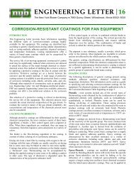
USING PERFORMANCE TABLES<br />
The performance tables in this bulletin are designed to provide<br />
performance ranges for groups of wheel diameters with common<br />
outlet sizes, based on direct drive operation at 3550 RPM.<br />
Through interpolation, a specific fan size can be selected for a<br />
given operating point at standard operating conditions. For example,<br />
to achieve 4000 CFM at 65” SP, the proper fan selection<br />
would be either Size 28510A, or Size 29010S, depending on<br />
desired wheel type. For more specific and accurate fan selection,<br />
refer to the fan-selection program in the nyb Electronic Catalog.<br />
SIZING NOMENCLATURE<br />
8–digit model number<br />
designates the wheel<br />
diameter, outlet size,<br />
wheel type, and nominal<br />
motor horsepower.<br />
280<br />
Wheel<br />
diameter<br />
Note: The last two digits<br />
showing motor horsepower<br />
are not required for<br />
Arrangement 1 <strong>Type</strong> <strong>HP</strong> <strong>Pressure</strong> <strong><strong>Blower</strong>s</strong>.<br />
EXAMPLE<br />
12 A<br />
Outlet<br />
size<br />
[inches]<br />
Wheel type<br />
A=aluminum<br />
S = steel/alloy<br />
50<br />
Nominal<br />
motor<br />
horsepower<br />
MAXIMUM SAFE SPEED<br />
Chart I details maximum safe speeds at 70˚F. When alloy<br />
construction is specified or when temperatures are involved,<br />
multiply the appropriate wheel safe speed shown in Chart I<br />
by the factor shown in Chart II. The unit safe speed at<br />
temperature is the lesser of the unit safe speed at 70˚F.<br />
[Chart I] and the wheel safe speed calculated at operating<br />
temperature and with the appropriate wheel material.<br />
CHART I<br />
MAXIMUM SAFE SPEEDS AT 70˚F.†<br />
Size Outlet Size Wheel<br />
Structure<br />
Arr. 4/8 Arr. 1<br />
270 - 290 04, 06, 08, 10, 12 3600 3600 3600<br />
300 - 320 06, 08, 10, 12, 14 3600 3600<br />
3600<br />
3200*<br />
330 - 350 08, 10, 12, 14 3600 3600 3200*<br />
360 - 380 10, 12, 14, 16 3600 3600 3200*<br />
* 300 - 320 with 12 and 14 outlet and 330 - 380 with all outlet sizes are<br />
limited due to low bearing life at higher speeds.<br />
† Maximum safe speeds apply only to wheels operated at or below the stated<br />
temperatures and free of material build-up, corrosion, or wear.<br />
Sizes 270-320 <strong>HP</strong>PB<br />
Temp. °F. INX 60 Aluminum Alloy 2205<br />
CHART II<br />
TEMPERATURE CORRECTION FACTORS FOR WHEEL SAFE SPEEDS<br />
Sizes 330-350 <strong>HP</strong>PB<br />
Temp. °F. INX 80 Aluminum Alloy 2205<br />
Sizes 360-380 <strong>HP</strong>PB<br />
Temp. °F. INX 80 Aluminum Alloy 2205<br />
70 1.0 1.0 1.0 70 1.0 1.0 1.0 70 1.0 1.0 0.97<br />
200 1.0 1.0 1.0 200 1.0 1.0 0.97 200 1.0 1.0 0.91<br />
300 1.0 — 1.0 300 1.0 — 0.93 300 1.0 — 0.88<br />
400 1.0 — 1.0 400 1.0 — 0.89 400 1.0 — 0.84<br />
500 1.0 — 0.97 500 1.0 — 0.86 500 1.0 — 0.81<br />
600 1.0 — 0.94 600 1.0 — 0.84 600 0.98 — 0.79<br />
PERFORMANCE<br />
Performance is based on actual cubic feet per minute<br />
[ACFM] at the blower inlet at standard density [.075 lbs./ft. 3 ]<br />
and static pressure at the blower outlet. Static pressure<br />
capabilities are shown in inches water gauge [”WG].<br />
Air density corrections are necessary for proper selection<br />
when air density varies from the standard .075 lbs./ft. 3 at<br />
70˚F. at sea level. This also occurs when negative static<br />
pressure exists [rarefication] on the inlet side of the fan.<br />
Multiply the required static pressure at conditions by the<br />
appropriate factors in Charts III, IV, and V to obtain corrected<br />
pressure for blower selection. <strong>Pressure</strong> and B<strong>HP</strong> will be<br />
reduced at conditions by the inverse of these factors.<br />
Multiply one factor by the other if temperature, altitude, and<br />
rarefication are non-standard. For example: If the installation<br />
is located at an altitude of 4000 feet, the gas temperature<br />
is 300˚F., and the inlet pressure is –40”WG, the correction<br />
factor is 1.84 [1.16 x 1.43 x 1.11].<br />
CHART III<br />
ALTITUDE [ft.]<br />
CORRECTIONS<br />
Alt. Factor<br />
0 1.00<br />
500 1.02<br />
1000 1.04<br />
1500 1.06<br />
2000 1.08<br />
2500 1.10<br />
3000 1.12<br />
3500 1.14<br />
4000 1.16<br />
4500 1.18<br />
5000 1.20<br />
6000 1.25<br />
7000 1.30<br />
8000 1.35<br />
9000 1.40<br />
10000 1.45<br />
CHART IV<br />
TEMPERATURE<br />
CORRECTIONS<br />
Temp.˚F. Factor<br />
0 .87<br />
20 .91<br />
40 .94<br />
60 .98<br />
70 1.00<br />
80 1.02<br />
100 1.06<br />
120 1.09<br />
140 1.13<br />
160 1.17<br />
180 1.21<br />
200 1.25<br />
300 1.43<br />
400 1.62<br />
500 1.81<br />
600 2.00<br />
CHART V<br />
RAREFICATION<br />
CORRECTIONS<br />
Neg. inlet<br />
pressure Factor<br />
“WG<br />
15 1.04<br />
20 1.05<br />
25 1.07<br />
30 1.08<br />
35 1.09<br />
40 1.11<br />
45 1.12<br />
50 1.14<br />
55 1.16<br />
60 1.17<br />
65 1.19<br />
70 1.21<br />
75 1.23<br />
85 1.26<br />
PAGE 6