Temperature and Altitude Affect Fan Selection - New York Blower
Temperature and Altitude Affect Fan Selection - New York Blower
Temperature and Altitude Affect Fan Selection - New York Blower

Create successful ePaper yourself
Turn your PDF publications into a flip-book with our unique Google optimized e-Paper software.
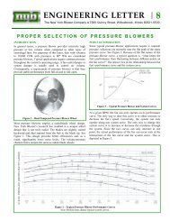
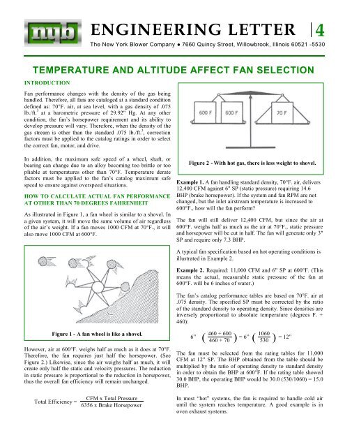
ENGINEERING LETTER 4The <strong>New</strong> <strong>York</strong> <strong>Blower</strong> Company ●7660 Quincy Street, Willowbrook, Illinois 60521 -5530TEMPERATURE AND ALTITUDE AFFECT FAN SELECTIONINTRODUCTION<strong>Fan</strong> performance changes with the density of the gas beingh<strong>and</strong>led. Therefore, all fans are cataloged at a st<strong>and</strong>ard conditiondefined as: 70°F. air, at sea level, with a gas density of .075lb./ft. 3 at a barometric pressure of 29.92" Hg. At any othercondition, the fan’s horsepower requirement <strong>and</strong> its ability todevelop pressure will vary. Therefore, when the density of thegas stream is other than the st<strong>and</strong>ard .075 lb./ft. 3 , correctionfactors must be applied to the catalog ratings in order to selectthe correct fan, motor, <strong>and</strong> drive.In addition, the maximum safe speed of a wheel, shaft, orbearing can change due to an alloy becoming too brittle or tooFigure 2 - With hot gas, there is less weight to shovel.pliable at temperatures other than 70°F. <strong>Temperature</strong> deratefactors must be applied to the fan’s catalog maximum safeExample 1. A fan h<strong>and</strong>ling st<strong>and</strong>ard density, 70°F. air, deliversspeed to ensure against overspeed situations.12,400 CFM against 6" SP (static pressure) requiring 14.6HOW TO CALCULATE ACTUAL FAN PERFORMANCE BHP (brake horsepower). If the system <strong>and</strong> fan RPM are notAT OTHER THAN 70 DEGREES FAHRENHEITchanged, but the inlet airstream temperature is increased to600°F., how will the fan perform?As illustrated in Figure 1, a fan wheel is similar to a shovel. Ina given system, it will move the same volume of air regardless The fan will still deliver 12,400 CFM, but since the air atof the air’s weight. If a fan moves 1000 CFM at 70°F., it will 600°F. weighs half as much as the air at 70°F., static pressurealso move 1000 CFM at 600°F.<strong>and</strong> horsepower will be cut in half. The fan will generate only 3"SP <strong>and</strong> require only 7.3 BHP.A typical fan specification based on hot operating conditions isillustrated in Example 2.Example 2. Required: 11,000 CFM <strong>and</strong> 6" SP at 600°F. (Thismeans the actual, measurable static pressure of the fan at600°F. will be 6 inches of water.)The fan’s catalog performance tables are based on 70°F. air at.075 density. The specified SP must be corrected by the ratioof the st<strong>and</strong>ard density to operating density. Since densities areinversely proportional to absolute temperature (degrees F. +460):Figure 1 - A fan wheel is like a shovel.460 + 600 10606”( 460 + 70 ) = 6” ( 530 ) = 12”However, air at 600°F. weighs half as much as it does at 70°F.Therefore, the fan requires just half the horsepower. (SeeThe fan must be selected from the rating tables for 11,000CFM at 12" SP. The BHP obtained from the table should beFigure 2.) Likewise, since the air weighs half as much, it willcreate only half the static <strong>and</strong> velocity pressures. The reductionmultiplied by the ratio of operating density to st<strong>and</strong>ard densityin order to obtain the BHP at 600°F. If the rating table showedin static pressure is proportional to the reduction in horsepower,thus the overall fan efficiency will remain unchanged.30.0 BHP, the operating BHP would be 30.0 (530/1060) = 15.0BHP.CFM x Total PressureIn most “hot” systems, the fan is required to h<strong>and</strong>le cold airTotal Efficiency = 6356 x Brake Horsepower until the system reaches temperature. A good example is inoven exhaust systems.
If Example 2 were such a case, the fan would require 30.0 BHPwhen operating at 70°F., <strong>and</strong> 15.0 BHP when the oven hadwarmed to 600°F. Very often a damper is furnished with the fanso that, during the warming-up period, the fan can be damperedto reduce the horsepower. Without the damper, a 30 HP motorwould be needed.Confusion can be avoided if the SP is specified at the temperatureit was calculated. In Example 2, the specifications should readeither:11,000 CFM <strong>and</strong> 6" SP at 600°F., or11,000 CFM for operation at 600°F. <strong>and</strong> 12" SP at 70°F.Table 1 gives correction factors used to convert from a nonst<strong>and</strong>arddensity to a st<strong>and</strong>ard density of 70°F. air. These factorsare merely the ratios of absolute temperatures. Multiply theactual static pressure by the specific temperature/altitude factorso st<strong>and</strong>ard catalog rating tables can be used. Divide the brakehorsepower from the catalog rating table by thetemperature/altitude factor to get BHP at conditions.Air<strong>Temperature</strong>°F.Table 1 - Corrections for <strong>Temperature</strong>FactorAir<strong>Temperature</strong>°F.Factor-50 0.77 275 1.39-25 0.82 300 1.430 0.87 325 1.48+20 0.91 350 1.5340 0.94 375 1.5860 0.98 400 1.6270 1.00 450 1.7280 1.02 500 1.81100 1.06 550 1.91120 1.09 600 2.00140 1.13 650 2.09160 1.17 700 2.19180 1.21 750 2.28200 1.25 800 2.38225 1.29 900 2.56250 1.34 1000 2.76<strong>Altitude</strong>Feet AboveSea LevelTable 2 - Corrections for <strong>Altitude</strong>Factor<strong>Altitude</strong>Feet AboveSea LevelFactor0 1.00 5000 1.20500 1.02 5500 1.221000 1.04 6000 1.251500 1.06 6500 1.272000 1.08 7000 1.302500 1.10 7500 1.323000 1.12 8000 1.353500 1.14 8500 1.374000 1.16 9000 1.404500 1.18 10000 1.45HOW TO CALCULATE ACTUAL FAN PERFORMANCEAT OTHER THAN SEA LEVELA fan operating at an altitude above sea level is similar to a fanoperating at air temperatures higher than 70°F.; it h<strong>and</strong>les airless dense than st<strong>and</strong>ard. Table 2 gives the ratio of st<strong>and</strong>ard airdensity at sea level to densities of 70°F. air at other altitudes.Example 3. Required: 5800 CFM at 6" SP at 5000 ft. altitude.70°F. air at sea level weighs 1.20 times as much as 70°F. air at5000 Ft. Therefore, at sea level, the SP is 1.2 x 6 = 7.20" SP.The fan would need to be selected for 5800 CFM at 7.2" SP at70°F. .075 density.When both heat <strong>and</strong> altitude are combined, the density of the airis modified by each, independently, so that the correction factorscan be multiplied together.Example 4. Required: 5800 CFM at 6" SP at 5000 ft. altitude at600°F. Air at 70°F. at sea level weighs 2.00 x 1.20 = 2.40 timesas much as 600°F. air at 5000 ft. altitude. At sea level <strong>and</strong> 70°F.,SP = 2.40 x 6 = 14.4" SP. Select a fan for 5800 CFM at 14.4"SP. Divide the brake horsepower in the rating table by 2.40 toobtain horsepower at 600°F. <strong>and</strong> 5000 ft. If the fan is to startcold, it will still be at 5000 ft. altitude. Therefore, to get the“cold” horsepower requirement, divide by 1.20, the altitudefactor only.DENSITY CHANGES FROM OTHER THAN HEAT ANDALTITUDE<strong>Fan</strong> densities may vary from st<strong>and</strong>ard for other reasons than heat<strong>and</strong> altitude. Moisture, gas, or mixtures of gases (other than air)are a few possibilities. In these cases, it is necessary to obtainthe actual density of the airstream gas by some other referencematerial. A similar factor, as shown in Table 1, is then createdusing the st<strong>and</strong>ard density of air .075 lb. per cubic foot divided bythe new density..075 lb./ft. 3Factor = special gas densityACFM-SCFM DEFINITIONThe terms ACFM <strong>and</strong> SCFM are often used in design work <strong>and</strong>cannot be used interchangeably.SCFM is St<strong>and</strong>ard Cubic Feet per Minute corrected to st<strong>and</strong>arddensity conditions. To determine the SCFM of the volume usedin Example 2, which was 11,000 CFM at 600°F., we wouldmultiply the CFM by the density ratios..03711000 x .075= 5500 SCFMThis indicates that if the weight of air at 600°F. were corrected tost<strong>and</strong>ard conditions its volume would be reduced to 5500 CFMACFM st<strong>and</strong>s for Actual Cubic Feet per Minute. It is the volumeof gas flowing through a system <strong>and</strong> is not dependent upondensity.The terms ACFM <strong>and</strong> SCFM are often used in system designwork where both quantities need to be known. It should beremembered, however, that since a fan h<strong>and</strong>les the same volumeof air at any density, ACFM should be used when specifying<strong>and</strong> selecting a fan.Page 2
FAN SAFE SPEED AND TEMPERATUREWhenever a fan is used to move air at temperatures substantiallyabove or below 70°F., care must be taken to ensure that the safespeeds of wheel <strong>and</strong> shaft are not exceeded, <strong>and</strong> that bearingtemperature <strong>and</strong> lubrication are satisfactory.The maximum safe speed of a particular fan must be determinedby calculations or actual tests. Safe speed depends entirely uponthe wheel <strong>and</strong> shaft assembly’s ability to withst<strong>and</strong> thecentrifugal forces created by its own weight. Highertemperatures can affect the wheel <strong>and</strong> shaft assembly’s ability towithst<strong>and</strong> these forces <strong>and</strong> therefore must be considered.Most metals become weaker at higher temperatures. Thisweakness is measurable in terms of yield <strong>and</strong> creep strength. Itcan be translated into formulas that accurately determine the safespeed of a wheel <strong>and</strong> shaft assembly in relation to its testedmaximum speed at st<strong>and</strong>ard conditions. Manufacturers providesafe speed reductions in their catalogs based on the alloy thatwas used to manufacture the wheel <strong>and</strong>/or shaft.Some metals withst<strong>and</strong> heat better than others. Certain grades ofstainless steel can be substituted to increase temperature limits.On the other h<strong>and</strong>, fan wheels constructed of aluminum shouldnever be operated above 200°F.For information regarding fiberglass reinforced plastic fanequipment, consult the appropriate product bulletin.Table 3 gives an indication of the speed derate factors for severaldifferent alloys. These are listed for reference purposes only.For a specific fan, consult the appropriate product bulletin.Table 3 - RPM Derate Factors By Material<strong>Temperature</strong>Stainless SteelMild Steel Aluminum°F.304L 316L 34770 1.0 1.0 1.0 1.0 1.0200 .97 .97 .88 .95 .95300 .95 -- .82 .92 .93400 .94 -- .78 .89 .90500 .93 -- .75 .86 .90600 .92 -- .73 .84 .90800 .80 -- -- .79 .861000 -- -- -- .75 .83The limiting temperature on any fan is the highest temperaturethat any component of the fan assembly will reach during anyoperating cycle. A fan in a process oven application may h<strong>and</strong>leair several hundred degrees above the highest temperature theoven reaches, especially during start-up. On such applications, atemperature indicator should be located in the fan inlet tocontrol the heat source <strong>and</strong> to keep the fan within its maximumsafe temperature. This is particularly true where burners arelocated on the inlet side of the fan. In all cases, the fan shouldremain in operation until the air is cooled to 180°F. or less toprevent “heat soaking” of the fan shaft which could cause sagging.Bearings must be kept cool; otherwise st<strong>and</strong>ard lubricants losetheir effectiveness <strong>and</strong> bearing failures are likely. For axial fans,where the bearings are located in the airstream, care must betaken to ensure proper lubrication. Special fan <strong>and</strong> bearingdesigns, as well as high temperature lubricants, are available toextend the operating range to higher temperatures.Arrangement 4 centrifugal fans, where the fan wheel is mountedon the motor shaft, should not be used above 180°F., unlessspecial provisions are made (i.e., a shaft cooler or heat shield) tokeep heat radiated from the housing from increasing motorbearing <strong>and</strong> winding temperatures.When fan bearings are located outside of the airstream, as inArrangement 1, 8, <strong>and</strong> 9 centrifugal fans, higher airstreamtemperatures are possible. Table 4 lists some typical maximumrecommended operating temperatures for fans using ball orroller bearings.A conventional fan using st<strong>and</strong>ard bearings <strong>and</strong> st<strong>and</strong>ard lubricantcan normally be operated to a maximum of approximately300°F. With the addition of a shaft cooler (Figure 3), thistemperature limitation can be extended to 650°F. The shaftcooler has the effect of absorbing <strong>and</strong> dissipating heat from theshaft while circulating air over the inboard bearing.Table 4 - Maximum <strong>Fan</strong> Inlet <strong>Temperature</strong>sArrangement 1 <strong>and</strong> 8 (Overhung Wheel)St<strong>and</strong>ard ConstructionWith Shaft CoolerWith Shaft Cooler <strong>and</strong> Heat GapWith Shaft Cooler, Heat Gap,Stainless Wheel, <strong>and</strong> Alloy Shaft300°F.650°F.800°F.1000°F.Arrangement 3 (Wheel Suspended Between Bearings)St<strong>and</strong>ard ConstructionArrangement 4 (Wheel on Motor Shaft)St<strong>and</strong>ard ConstructionEnclosed Bearing <strong>Fan</strong>s (Axial <strong>Fan</strong>s)Arrangement 4Arrangement 9With Special V-Belts with 2.0 S.F.Arrangement 9 Duct <strong>Fan</strong>With Heat-<strong>Fan</strong> ConstructionArrangement 3Arrangement 4Plenum <strong>Fan</strong>sFigure 3 – Shaft Color200°F.180°F.105°F.120°F.200°F.600°F.105°F.105°F.Page 3
With the addition of a heat gap (Figure 4) the temperaturelimitation can be extended to 800°F. since the fan pedestal isisolated from the hot fan housing. For specific applications,consult the appropriate product bulletin. Also, recognize thatthese limitations apply only to bearings <strong>and</strong> that wheel <strong>and</strong>shaft limitations must be treated independently.All of the foregoing is based on the use of st<strong>and</strong>ard lubricants.When high-temperature lubricants are required, the type oflubricant <strong>and</strong> the frequency of relubrication are normally muchmore critical.When the fan shaft is heated to the point that it exp<strong>and</strong>s morethan the structure to which it is attached, one expansion bearing<strong>and</strong> one fixed bearing should be furnished. The fixed bearing islocated on the drive end of the fan while the floating bearing islocated next to the fan. This arrangement, however, is notcritical <strong>and</strong> may vary by manufacturer.When the fan is h<strong>and</strong>ling air below 70°F., there is the possibilityof other problems. Below -30 to -50°F., ordinary steel is toobrittle. Aluminum wheels or wheels of steel containing at least5% nickel must be used, <strong>and</strong> shafts must be made of nickelbearingsteel. In addition, lubricants become stiff, or even solid inthese low-temperature applications. Exact operating conditionsshould be given to the fan manufacturer to relay to the bearingsupplier for proper selection.CALCULATING “HOT” RESISTANCE FOR SYSTEMSFigure 5 shows a system that operates at the same temperaturethroughout. If the inlet temperature is known, the fan may beselected from the fan capacity tables <strong>and</strong> the rated horsepower <strong>and</strong>static pressure corrected by the temperature correction factorfrom Table 1. However, what happens to the system that the fanwas operating against? If a fixed system, which originally wascalculated for st<strong>and</strong>ard air, was subjected to the same temperatureincrease as the fan, then system static pressure will change <strong>and</strong> beidentical to the fan static pressure change. The result is that if afan <strong>and</strong> system operate together the flow will remain unchanged.(See Figure 6.) Unfortunately, this example assumes that theentire system is being subjected to the same temperature change,which is not always the case.Figure Figure 4 – 4 “Heat – “Heat Gap” Gap” betweenfan <strong>and</strong>fan <strong>and</strong> bearing.Figure 6 – <strong>Fan</strong>-system curve relationshipwith fan <strong>and</strong> system at the same temperature.Figure 5 – A system with the same temperature throughout.Page 4
Figure 7 shows a system in which different temperatures areinvolved. The fan will not h<strong>and</strong>le the same volume of air whenoperating hot as it does when cold. If the burner is on, the fanwill h<strong>and</strong>le 1430 ACFM against an actual static pressure of 1.2inches. This is arrived at by adding the filter, burner, <strong>and</strong> nozzleresistance, neglecting for the sake of simplicity any externalresistance from additional ductwork. The fan would be selectedfrom the capacity tables on the basis of 1430 CFM at 1.72inches static pressure (300°F. correction factor times 1.2inches).If the burner is turned off while the fan continues to operate atthe same RPM, it is necessary to determine the systemcharacteristic curve <strong>and</strong> plot its intersection with the fan todetermine how much air the fan would move <strong>and</strong> at what staticpressure. To accomplish this we must assume an arbitrarycapacity, such as 1000 CFM at 70°F. The filter louver resistancewould be the same, cold or hot, at .3 inches 70°F. The burnerresistance would remain unchanged with temperature since it mustbe assumed that air expansion takes place after the highvelocity section of the burner. The nozzles will vary inresistance directly as the density changes <strong>and</strong> inversely as thesquare of the flow. The nozzle would then have a resistance coldat 1000 CFM of:1000.5” x ( 1430 ) 2 x 1.43 = .35”Summing these resistances yields the cold resistance at 1000CFM of 1 .05"SP. This new system point <strong>and</strong> correspondingcurve are then plotted against a fan curve at st<strong>and</strong>ard conditionssuch that the resulting intersection will be the final operatingpoint of the cold system. Using an actual fan as an example,the resulting flow would be 1220 CFM at 1.5 inches staticpressure. (See Figure 8.)Figure 8 - <strong>Fan</strong>-system curve relationship withfan at different temperatures.Figure 7 - A system with different temperatures.Page 5
FAN LOCATION IN HOT PROCESS SYSTEMSFigure 9 shows how a fan may be located more economically inone part of a system, as contrasted to another. Suppose 10,000CFM is to be heated from 70°F. to 600°F. Obviously, the heaterwill require the same 3-inch pressure differential whether thefan is to push the air into, or pull the air out of, the heater.A fan pushing air into the heater would be specified to h<strong>and</strong>le10,000 CFM at 70°F. against 3 inches of static pressure at70°F. One possible selection is a fan with a 27-inch wheeldiameter, Class I design utilizing a 71 / 2 HP motor.The alternative fan, pulling air from the heater, would bespecified to h<strong>and</strong>le 20,000 ACFM at 600°F. against 3" SP at600°F. It would be selected from the capacity tables for 20,000CFM at 6" SP. One suitable choice is a fan with a 3 61 / 2-inchwheel diameter, Class II design utilizing a 15 HP motor. (Note:26 HP, from the tables, at 70°F., divided by temperaturecorrection factor, is 13 HP at 600°F.) This example illustrateswhy it is usually more economical to locate the fan at thecoolest part of the system. In this case, the “push” fan mightcost half as much as the “pull” fan.Figure 9 - The importance of fan location.Form 607 GAW