handling fans - New York Blower
handling fans - New York Blower
handling fans - New York Blower

Create successful ePaper yourself
Turn your PDF publications into a flip-book with our unique Google optimized e-Paper software.
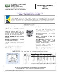
AIR-HANDLING FANSAXIAL FLOWDuct FansTubeaxial FansVaneaxial FansTubular AcoustaFoil ®PROPELLERPropeller FansFansAIRFOIL/BACKWARD INCLINEDSingle-Width AcoustaFoil/PLR FansDouble-Width AcoustaFoil FansClass IV FansHIGH CAPACITYAF-Forty FansPRESSURE BLOWERSPressure <strong>Blower</strong>sType HP Pressure <strong>Blower</strong>sPACKAGED FANSGeneral Purpose FansGPA FansJunior FansROOF VENTILATORSRoof Ventilators - Hooded/ UpblastDUST AND MATERIAL-HANDLING FANSRADIAL TIPNEW YORK BLOWERRTS FansSeries 60 FansCATALOG INDEXGENERAL INDUSTRIALCompact GI FansSeries 20 GI FansSeries 30 GI FansSeries 45 GI FansCORROSION-RESISTANT FANSFRPGeneral-Purpose Fume ExhaustersFume ExhaustersRadial Fume ExhaustersPressure <strong>Blower</strong>sTubeaxial FansSPECIAL PURPOSE PRODUCTSHEATING EQUIPMENTUnit HeatersSTEELfin CoilsFAN COMPONENTSPlug FansAir KitsPlenum FansFC DWDI FansAcF/PLR ComponentsACCESSORIESDAMPERS, INLET BOXESOutlet DampersInlet Boxes and Inlet-Box DampersMISCELLANEOUSSilencersYour <strong>New</strong> <strong>York</strong> <strong>Blower</strong> Representative® Registered trademark of The <strong>New</strong> <strong>York</strong> <strong>Blower</strong> Company, Willowbrook, IL
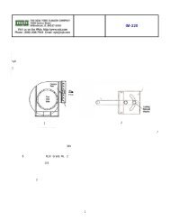
OUTLET DAMPER DIMENSIONSNotes: 1. Control arm located on inlet side of fan. 2. Control arm swings 45° each side of centerline.3. Mounting holes on 4” centers from centerline. 4. Dimensions not to be used for construction unless certified.ACOUSTAFOIL/PLR, GENERAL PURPOSE, AF*, RTS* FANS - DIMENSIONS [INCHES]SizeB E MNo. holes per flangeDamper Inside AreaDia.Top and Bottom(ft 2 ) Weight (lbs)AcF/PLR, AC DFAF, RTSSidesHolesGPSW DWSW DWSW DWSW DWSW DW SW DW10 -- 133/8 101/8 -- 5/8 113/8 5 -- 3 81/8 -- 3 1 -- 5/16 0.61 -- 15 --12 -- 153/4 113/8 -- 5/8 133/4 5 -- 33/8 93/8 -- 3 3 -- 5/16 0.86 -- 20 --13 -- 171/4 123/8 -- 5/8 151/4 5 -- 33/4 103/8 -- 5 3 -- 5/16 1.05 -- 25 --15 -- 187/8 133/8 -- 5/8 167/8 5 -- 37/8 113/8 -- 5 3 -- 5/16 1.28 -- 30 --16 -- 21 1/8 143/4 -- 3/4 185/8 5 -- 41/2 121/4 -- 5 3 -- 7/16 1.50 -- 38 --18 -- 23 163/8 271/4 3/4 201/2 5 10 37/8 137/8 243/4 5 3 5 7/16 1.89 3.41 44 7920 24 25 171/2 291/2 3/4 221/2 5 10 41/8 15 27 7 3 7 7/16 2.25 4.09 56 8222 27 273/8 193/8 325/8 3/4 247/8 8 10 133/4 167/8 301/8 7 3 7 7/16 2.81 5.06 65 8424 30 303/8 21 1/2 361/4 7/8 273/8 10 10 151/4 181/2 331/4 7 5 7 7/16 3.40 6.16 79 10227 33 331/4 233/8 391/2 7/8 301/4 10 10 141/8 203/8 361/2 9 5 9 7/16 4.15 7.49 96 12430 36 361/2 255/8 431/2 7/8 331/2 10 10 151/2 225/8 401/2 9 5 9 7/16 5.12 9.23 118 15233 40 397/8 277/8 475/8 7/8 367/8 10 10 143/4 247/8 445/8 9 5 11 7/16 6.21 11.22 143 18536 44 443/4 311/2 531/4 11/8 403/4 10 10 165/8 271/2 491/4 11 7 11 9/16 7.61 13.70 175 22540 49 487/8 343/8 583/8 11/8 447/8 10 10 161/8 303/8 543/8 11 7 13 9/16 9.27 16.69 180 27444 54 535/8 371/2 64 11/8 495/8 10 10 157/8 331/2 60 13 7 15 9/16 11.33 20.39 186 32549 60 585/8 407/8 701/8 11/8 545/8 10 10 153/4 367/8 661/8 15 9 17 9/16 13.75 24.77 226 39454 66 643/8 443/4 771/8 11/8 603/8 10 10 153/4 403/4 731/8 15 9 17 9/16 16.82 30.31 276 48260 73 707/8 49 843/4 11/8 667/8 10 10 16 45 803/4 17 11 19 9/16 20.61 37.12 338 82366 -- 771/2 531/2 927/8 11/8 731/2 10 10 161/4 491/2 887/8 19 11 21 9/16 24.95 44.94 408 99673 -- 851/4 583/4 1021/4 11/8 81 1/4 10 10 163/4 543/4 981/4 21 13 25 9/16 30.54 54.97 499 1217* The dimensions shown here are for <strong>fans</strong> without evases. Consult nyb for the dimensions of dampers to be used on the discharges of evases.M and D are outside dimensions to match fan M and D dimensions. Tolerance: ± 1/8”GENERAL INDUSTRIAL FANS - DIMENSIONS [INCHES]Size A B C D E F MTotalFlangeHolesDia.HolesDamperInside area(ft 2 )Weight(lbs)14 103/4 103/8 3/4 81/4 7 33/8 77/8 8 7/16 0.41 1317 125/8 12 3/4 101/8 7 33/4 91/2 12 7/16 0.62 2019 131/8 123/4 7/8 101/8 7 4 93/4 12 7/16 0.63 2522 16 133/4 7/8 13 8 33/4 103/4 12 7/16 0.91 2926 18 153/8 7/8 15 7 4 123/8 16 7/16 1.22 3829 197/8 17 7/8 167/8 10 43/8 14 16 7/16 1.56 4833 213/4 185/8 7/8 183/4 10 81/2 155/8 16 7/16 1.95 6036 233/4 201/4 7/8 203/4 10 91/4 171/4 20 7/16 2.39 7340 267/8 23 11/8 227/8 10 105/8 19 24 9/16 2.91 8945 293/4 253/8 11/8 253/4 10 115/8 213/8 24 9/16 3.70 11350 323/4 277/8 11/8 283/4 10 105/8 237/8 24 9/16 4.63 14157 365/8 31 1/8 11/8 325/8 10 183/8 271/8 32 9/16 5.99 15164 401/2 341/2 11/8 361/2 10 171/4 301/2 32 9/16 7.56 16271 443/8 375/8 11/8 403/8 10 187/8 335/8 36 9/16 9.24 17378 481/4 407/8 11/8 441/4 10 201/2 367/8 40 9/16 11.12 20985 521/4 441/8 11/8 481/4 10 261/8 401/8 44 9/16 13.22 247M and D are outside dimensions to match fan M and D dimensions. Tolerance: ± 1/8”MATERIAL SPECIFICATIONSDamper case and flangesSizes 10 - 15 AcF/PLR: 12 gaugeAll others: 7 gaugeVanes14 gauge 10 gauge 7 gauge40-73 SW 10-36 SW 60-73 DW30-54 DW 18-27 DW49-73 AF/RTS 24-44 AF/RTS57-85 GI 14-50 GIVane Rods5/8” diameter all SW, GI and18-40 DW dampers3/4” diameter 44-73 DW dampersControl arm and linkage bars1/4” x 11/4” steel
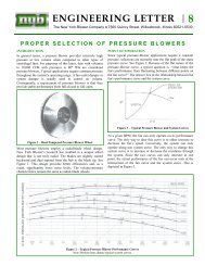
INLET BOXES AND INLET-BOX DAMPERSAvailable on these Arrangement 1, 4, 8, 9, 9F, and 10 <strong>fans</strong>:GENERAL PURPOSE FANSACOUSTAFOIL/PLR FANSCLASS IV FANSAF FANSRTS FANSGI FANSINLET BOXESAn inlet box is often used to accomplish a 90° turn intothe fan inlet. The use of a properly designed inlet box willprovide predictable minimum entry losses normallyassociated with a 90° turn at the fan inlet .. . see page 4for correction factors.The inlet box is designed to attach to the inlet flange ofthe fan. A support leg with mounting plate is standard onall inlet boxes . . . see dimension tables on page 2. Whena fan with inlet box is furnished complete with a unitarybase or isolation base, the base must be extended tomeet the support leg. See the separate Unitary Basesand Isolation Bases price list. The inlet box/support legassembly is not intended to support additional weightfrom ductwork or any other system components.Inlet boxes can also be equipped with drains and boltedcleanout doors.INLET-BOX POSITIONSPosition of inlet boxis determined fromdrive side of fan.Inlet box positions135°, 180°, and225° often requirespecial constructionto avoid interferencewith the fan supportstructure. Whenother accessoriessuch as an inlet-boxdamper or unitarybase are required, aspecial layout isnecessary ... consultnyb.INLET-BOX DAMPERSA parallel-blade inlet-box damper will control airflow byspinning the air into the fan. Reducing airflow by meansof an inlet-box damper saves horsepower, similar to anoutlet damper.Parallel-blade inlet-box dampers are available with thefollowing bearing options for the maximum temperatureshown:Notes:Standard aluminum sleeve bushings . . . . . . .300°F.Optional stainless-steel bushings . . . . . . . .1000°F.Optional stuffing-box construction . . . . . . . .1000°F.Optional ball-bearing construction . . . . . . . . 800°F.1. Maximum safe operating temperature ofthe fan may be lower than inlet-boxdamper limits.2. High-temperature paint is furnished foroperation above 300°F.3. Stainless-steel vanes and vane rods arefurnished for operation above 800°F.Inlet boxes and inlet-box dampers are normally shippedseparate from the fan . . . refer to separate Installationand Maintenance Instructions for further information.12345Catalog Sheet CS-721September 2002
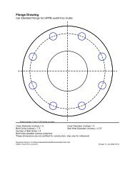
INLET BOXES FORGENERAL PURPOSE FANS,ACOUSTAFOIL/PLR FANS,CLASS IV FANS, AF FANS,RTS FANS1. Refer to page 3 for rectangular flangedimensions.2. Round flange dimensions on inlet boxmatch fan inlet flange dimensions.3. Base-bar dimensions match fan pedestalbase-bar dimension T.4. Dimensions are in inches.5. Dimensions not to be used for construtionunless certified.DIMENSIONS [inches]Fan size Fan Base hole diameterGP, inlet GP CL. IV Wt.AF,C E X Y ZAF,GaugeAcF/PLR area AcF/PLR, w/HDI [lbs.]RTSRTSCl. IV [ft.] Cl. IV Option18 -- 2.181 271/2 15 101/8 103/4 211/2 9/16 -- 9/16 12 8320 24 2.578 307/16 169/16 111/8 109/16 221/4 9/16 3/4 9/16 12 9822 27 3.341 331/2 181/4 121/4 115/8 241/2 9/16 3/4 3/4 12 11324 30 3.939 37 201/8 139/16 123/16 263/8 3/4 3/4 3/4 12 14027 33 4.746 401/2 22 147/8 127/8 283/8 3/4 3/4 3/4 12 16830 36 5.894 451/8 241/2 169/16 1311/16 307/8 3/4 1 3/4 10 24233 40 7.117 495/8 27 183/16 169/16 355/8 3/4 1 3/4 10 28836 44 8.781 551/8 30 201/16 177/16 383/8 7/8 1 1 10 34740 49 10.499 601/4 323/4 22 183/8 411/4 7/8 1 1 10 41944 54 13.028 671/8 361/2 247/16 195/16 445/8 7/8 1 1 10 51449 60 15.830 74 401/4 27 203/8 481/4 7/8 1 1 10 61954 66 19.228 815/8 443/8 297/8 243/4 557/8 1 1 1 10 73260 73 23.848 903/4 493/8 33 263/16 601/2 1 1 1 10 87666 -- 28.767 993/4 541/4 361/4 275/8 651/4 1 -- 1 10 92673 -- 35.454 1103/4 601/4 401/8 291/4 703/4 1 -- 1 10 1129Tolerance: ± 1/8”INLET BOXES FORGI FANSFAN¢HEIGHT(2)BASEHOLES1. Refer to page 3 for rectangular flangedimensions.2. Round flange dimensions on inlet boxmatch fan inlet flange dimensions.3. Base-bar dimensions match fan pedestalbase-bar dimension T.4. Dimensions are in inches.5. Dimensions not to be used for construtionunless certified.FAN¢HEIGHT(2)BASEHOLESDIMENSIONS [inches]Fan Fan inlet Base Wt.C E X Y ZGa.size area [ft. 2 ] hole dia. [lbs.]224 .921 193/4 101/2 87/8 8 171/2 9/16 12 64264 1.227 223/4 121/8 101/8 9 193/4 3/4 12 81294 1.576 257/8 133/4 111/2 95/8 213/4 3/4 12 102334 1.968 29 151/2 123/4 103/8 233/4 3/4 12 126364 2.405 321/8 171/8 141/8 131/8 281/8 7/8 12 159404 2.885 351/8 183/4 151/2 137/8 301/4 7/8 12 203454 3.687 397/8 211/4 181/2 141/2 337/8 7/8 12 255504 4.586 441/2 233/4 199/16 159/16 36 1 12 310574 5.939 505/8 271/8 213/4 167/8 40 1 10 435644 7.466 565/8 301/4 2411/16 181/16 441/8 1 10 522714 9.168 627/8 335/8 277/16 195/16 481/8 1 10 620784 11.044 69 367/8 301/16 207/16 517/8 1 10 722854 13.095 751/4 401/4 323/4 211/2 555/8 1 10 836Page 2Tolerance: ± 1/8”
INLET BOX DAMPERS FORGENERAL PURPOSE FANS,ACOUSTAFOIL/PLR FANS,CLASS IV FANS, AF FANS,RTS FANS, GI FANS1. A and B are inside dimensions.2. Control arm (1/4” x 1-1/4” bar), formanual or automatic operation, suppliedon side away from fan.3. Control arm swings 45° each side ofcenterline.4. Damper flange is 7-gauge steel withholes on 4” centers from centerlines.5. Stuffing-box damper furnished withpacking boxes on vane rods onlinkage side, and with caps on the sideopposite the linkage.6. Specify fan rotation.7. Dimensions are in inches.8. Dimensions not to be used for constructionunless certified.2-1/4”BALL BRG. ONLY2-3/4” STD.3-3/4” STUFF BOX4-1/2” BALL BRG.DIMENSIONS [inches]GENERAL PURPOSE FANS, ACOUSTAFOIL/PLR FANS,CLASS IV FANS, AF FANS, RTS FANSDamperFlange holesFan Sizeinlet Number Wt.A B F G H J NGP, AcF/ AF, area Top and Dia. [lbs.]SidePLR, Cl. IV RTS [ft. 2 ] bottom18 -- 2.17 25 121/2 141/8 27 281/4 141/2 153/4 14 6 9/16 7120 24 2.67 273/4 137/8 10 293/4 31 157/8 171/8 14 6 9/16 8122 27 3.23 301/2 151/4 167/8 321/2 333/4 171/4 181/2 18 6 9/16 9124 30 3.96 333/4 167/8 217/8 361/4 38 193/8 211/8 18 10*/6† 9/16 10327 33 4.75 37 181/2 205/8 391/2 411/4 21 223/4 18 10 9/16 11730 36 5.91 411/4 205/8 223/4 433/4 451/2 231/8 247/8 22 10 9/16 13333 40 7.11 451/4 225/8 275/8 473/4 491/2 251/8 267/8 26 10 9/16 15236 44 8.77 501/4 251/8 271/4 523/4 541/2 275/8 293/8 26 14*/10† 9/16 17340 49 10.50 55 271/2 323/8 571/2 591/4 30 313/4 30 14 9/16 19744 54 13.03 611/4 305/8 357/8 633/4 651/2 331/8 347/8 34 14 9/16 22849 60 15.82 671/2 333/4 357/8 70 713/4 361/4 38 34 18 9/16 26454 66 19.27 741/2 371/4 393/8 77 783/4 393/4 411/2 38 18 9/16 30060 73 23.78 823/4 413/8 47 851/4 87 437/8 455/8 42 22 9/16 34566 -- 28.75 91 451/2 503/4 931/2 951/4 48 493/4 46 26 9/16 40373 -- 35.42 101 501/2 525/8 1031/2 1051/4 53 543/4 50 26 9/16 465* Inlet box † Inlet-box damper Tolerance: ± 1/8”DIMENSIONS [inches] - GI FANSTO OUTSIDE OFCONTROL ARM1” STD.1” STUFF BOX2-1/2” BALL BRG.DamperFlange holesFan inlet Number Wt.A B F G H J NSize area Top and Dia. [lbs.]Side[ft. 2 ]bottom224 1.76 221/2 111/4 127/8 241/2 253/4 131/4 141/2 14 6 7/16 62264 2.35 26 13 145/8 28 291/4 15 161/4 14 6 7/16 73294 3.02 291/2 143/4 163/8 311/2 323/4 163/4 18 14 6 7/16 85334 3.78 33 161/2 207/8 35 361/4 181/2 193/4 18 10*/6† 7/16 98364 4.63 361/2 181/4 197/8 381/2 393/4 201/4 211/2 18 10 7/16 110404 5.56 40 20 221/8 421/2 441/4 221/2 241/4 22 10 9/16 122454 7.19 451/2 223/4 247/8 48 493/4 251/4 27 26 10 9/16 145504 8.94 503/4 253/8 271/2 531/4 55 277/8 295/8 26 14 9/16 170574 11.58 573/4 287/8 337/8 601/4 62 313/8 331/8 30 14 9/16 201644 14.56 643/4 323/8 341/2 671/4 69 347/8 365/8 34 14 9/16 236714 17.88 713/4 357/8 38 741/4 76 383/8 401/8 38 18 9/16 268784 21.53 783/4 393/8 443/8 811/4 83 417/8 435/8 42 18 9/16 308854 25.68 86 43 481/4 881/2 901/4 451/2 471/4 46 22 9/16 352* Inlet box † Inlet-box damperPage 3Tolerance: ± 1/8”AirflowCLOSE (CCW FAN)OPEN (CW FAN)OPEN (CCW FAN)CLOSE (CW FAN)11/16” DIA. HOLE