Create successful ePaper yourself
Turn your PDF publications into a flip-book with our unique Google optimized e-Paper software.
BULLETIN 631OCTOBER, 2009SINGLE AND DOUBLEAIR KITSDOUBLE AIR KITS• Capacities to 100,000 CFM• Pressures to 6”WG• Temperatures to 1000°F.SINGLE AIR KITS• Capacities to 84,000 CFM• Pressures to 6”WG• Temperatures to 1000°F.THE NEW YORK BLOWER COMPANY7660 Quincy StreetWillowbrook, IL 60527-5530Visit us on the Web: http://www.nyb.comPhone: (800) 208-7918 Email: nyb@nyb.com
AIR KITS<strong>Air</strong> <strong>Kits</strong> are ideal for applications where even air distributionis critical <strong>and</strong> where plenum construction <strong>and</strong> space limitationsfavor slower speed, center-hung fan designs.Sizes 24 to 44 housing.Riveted-wheel constructionSizes 12 to 22.Welded-wheel constructionSizes 24 to 44.DESIGN FEATURES•Two models to choose from:<strong>Single</strong> <strong>Air</strong> <strong>Kits</strong> in Sizes 12” to 44” for capacities to84,000 CFM.<strong>Double</strong> <strong>Air</strong> <strong>Kits</strong> in Sizes 12” to 33” for capacities to100,000 CFM.• Pressures to 6”WG.•Operating temperatures to:800°F. with st<strong>and</strong>ard wheels.1000°F. with stainless-steel wheels.• Forward-curved wheel:<strong>Double</strong> width-double inlet for maximum capacity.Slow speeds for quiet operation <strong>and</strong> economical shaftdiameters.Time-tested operating clearances for ease of installation<strong>and</strong> system expansion at operating temperature.• Suitable for clockwise <strong>and</strong> counterclockwise applications.CONSTRUCTION FEATURES•Housing—continuously welded, heavy-gauge steel. Sizes12” to 22” have streamlined venturi inlets pressed intohousing sides.•Wheels—double width-double inlet with optimized number<strong>and</strong> spacing of forward-curved blades. Riveted constructionin Sizes 12” to 22”, welded construction inSizes 24” to 44”.•Balance—all wheels receive a centrifugal precisionbalanceprior to shipment.•Finish—high-temperature, industrial-grade coating suitablefor applications at 1000°F.•Shafting—turned, ground, <strong>and</strong> polished shafting isstraightened to close tolerance to minimize “run-out” <strong>and</strong>ensure smooth operation.5-PART SIZING NOMENCLATUREEXAMPLEX 12 B 23 – 2Wheeldiameter[inches].X = Non-st<strong>and</strong>ard <strong>Air</strong> Kit.No letter = St<strong>and</strong>ard <strong>Air</strong> Kit.Currentdesignsequence.Shaftdiameter[sixteenthsof an inch].1= <strong>Single</strong> <strong>Air</strong> Kit.2 = <strong>Double</strong> <strong>Air</strong> Kit.Copyright © 2009 by The <strong>New</strong> <strong>York</strong> <strong>Blower</strong> Company. ® Registered trademark of The <strong>New</strong> <strong>York</strong> <strong>Blower</strong> Company.PAGE 2
ACCESSORIESMODIFICATIONS•ACCESS DOORFlush-bolted access door allows for system inspection<strong>and</strong> ease of wheel removal. Closely spaced studs holdbolted access door firmly against gasketing to minimizeleakage. With housing in clockwise Top Horizontal discharge,door available at 6, 9, <strong>and</strong> 12 o’clock positions.•SHAFT-COOLER ASSEMBLYIncludes cast-aluminum wheel, cooler cone, <strong>and</strong> metalguard. Dissipates heat prior to bearings.Recommended for applications 300°F. <strong>and</strong> above.• SHAFTINGHigh-quality, hot-rolled, turned, ground, <strong>and</strong> polishedof the appropriate alloy. Keyways <strong>and</strong> turndowns perspecification.•SPECIAL-ALLOY CONSTRUCTION<strong>Air</strong>stream components can be constructed of a widerange of alternate alloys for temperature <strong>and</strong> corrosionresistance including 304, 316, <strong>and</strong> 347 stainless steel.• BEARINGSPillow-block ball bearings pre-selected by shaft size forextended service life. Bearing pair includes one fixed<strong>and</strong> one expansion bearing to allow for thermal growthof the shaft.•STRAIGHTENING VANESInstalled in <strong>Air</strong> Kit inlets. Straightening vanes eliminatethe need for baffles in closed plenums by preventing thespinning of air at the inlet.•OTHER ACCESSORIESAlso available from nyb are drive components such asmotors <strong>and</strong> v-belt drives as well as a variety of preventative-maintenanceproducts including vibration detectors<strong>and</strong> bearing-temperature detectors.Shaftcoolerassembly.<strong>Air</strong> Kit withstraightening vanes.Access doorat 9 o’clock position.ELECTRONIC CATALOGA complete <strong>New</strong> <strong>York</strong> <strong>Blower</strong> Catalog on one CD. No more manual calculations <strong>and</strong>bulky product catalogs. A critical tool for all system-designers <strong>and</strong> engineers who select<strong>and</strong> specify air-moving equipment.SELECTION BENEFITSCATALOG CONTENTSFast, accurate fan selection.Fan-selection program.• Automatic altitude, temperature, • Complete product catalog in PDF including<strong>and</strong> density corrections.drawings, dimensions, <strong>and</strong> design specifications.Sound levels by octave b<strong>and</strong>.Sample guide specifications.Fan-performance curves.<strong>New</strong> <strong>York</strong> <strong>Blower</strong> Engineering Letters.Multiple model <strong>and</strong> size choices.Installation <strong>and</strong> Maintenance Manuals.• Metric or English units. • Listing of <strong>New</strong> <strong>York</strong> <strong>Blower</strong> representatives.To obtain your copy of <strong>New</strong> <strong>York</strong> <strong>Blower</strong>’s Electronic Catalog contact your local <strong>New</strong> <strong>York</strong><strong>Blower</strong> representative or go to www.nyb.com <strong>and</strong> click on Selection Software.PAGE 3
PLENUM DESIGNThe capacity tables on pages 7, 8, <strong>and</strong> 9 are based on laboratory tests of <strong>Air</strong> <strong>Kits</strong> withoutplenums [no restriction to airflow]. When <strong>Air</strong> <strong>Kits</strong> are mounted in restricted areas, the performancemay be affected. The following plenum information will assist the system designer inidentifying <strong>and</strong> applying the appropriate correction factors to obtain the desired catalog rating.OPEN PLENUM <strong>Air</strong> enters from more than one direction.CHART IOPEN PLENUM FACTORSDo not use for closed plenums.A in % ofwheel diameterMultiplyRPM by BHP by33 1 ⁄3% or more 1.00 1.0030% 1.01 1.0325% 1.04 1.1320% 1.10 1.3315% or less Poor design<strong>Double</strong><strong>Air</strong> KitA 2A AAA<strong>Single</strong><strong>Air</strong> KitCLOSED PLENUM <strong>Air</strong> enters from only one direction.<strong>Air</strong> Kit performance willchange due to restriction atthe inlet or spinning of airinto inlet. Spinning can beeliminated by centering faninlets in plenum, by designingbaffles as shown, or byinstalling optional straighteningvanes.When Z dimension isgreater than two timeswheel diameter, considerplenum as open type.BEST DESIGNSC = D, fan inlet is centered in airflow.ZCDCPOOR DESIGNSFan inlets not centered <strong>and</strong> no baffles used.DCDZGOOD DESIGNSFans not centered in airflow but vanes or bafflesinstalled to balance airflow into inlets.ZZZZZZZOutletvelocityCHART IIVELOCITY PRESSURESVelocitypressureOutletvelocityVelocitypressure800 .040 2600 .4221000 .063 2800 .4891200 .090 3000 .5601400 .122 3200 .6381600 .160 3400 .7211800 .202 3600 .8082000 .250 3800 .9002200 .302 4000 .9982400 .360 4200 1.100CLOSED PLENUM EXAMPLEAssume: 3600 fpm fan outlet velocity, 4” staticpressure, A = 33 1 ⁄3% wheel diameter.A in % ofwheel diameterVP =SPVelocityPressuredividedbyStaticPressureCHART IIICLOSED PLENUM CORRECTION FACTORS33 1 ⁄3%40% 60%RPM BHP RPM BHP RPM BHP.1 1.02 1.10 1.02 1.07 1.01 1.03.2 1.04 1.15 1.04 1.11 1.02 1.06.3 1.06 1.20 1.05 1.14 1.02 1.07.5 1.08 1.25 1.06 1.19 1.03 1.08.75 1.11 1.29 1.07 1.22 1.03 1.091.0 1.12 1.32 1.07 1.23 1.03 1.102.0 1.15 1.37 1.07 1.24 1.04 1.113.0 1.16 1.42 1.08 1.25 1.04 1.125.0 1.17 1.48 1.08 1.26 1.05 1.121. Velocity Pressure from Chart II at 3600 FPM = .8082. Velocity Pressure =.808 = .2Static Pressure 4.03. From Chart III multiply RPM by 1.04 <strong>and</strong> multiply BHP by 1.15PAGE 4
AIR KIT ENGINEERINGGENERAL<strong>Air</strong> <strong>Kits</strong> are an integral part of the ovens <strong>and</strong> dryers inwhich they are installed. As such, <strong>New</strong> <strong>York</strong> <strong>Blower</strong> salesrepresentatives work closely with OEM project engineersin assessing requirements <strong>and</strong> meeting critical performance<strong>and</strong> dimensional specifications. Because of thewide variety of plenum designs <strong>and</strong> <strong>Air</strong> Kit configurationsavailable final selection should be made using <strong>New</strong> <strong>York</strong><strong>Blower</strong>’s Electronic Catalog software.SINGLE OR DOUBLE AIR KITSThe choice of a single or double fan arrangement mustbe made to determine specific fan capabilities. Spaceavailability, uniform air distribution, performance requirements,<strong>and</strong> past plenum designs must all be consideredin the choice of single or double <strong>Air</strong> <strong>Kits</strong>.CORRECTION FACTORSFan performance is based on actual cubic feet per minute[ACFM] at the fan inlet at st<strong>and</strong>ard density [.075 lbs./ft. 3 ]<strong>and</strong> static pressure at the fan outlet. Static pressurecapabilities are shown in inches water gauge [”WG].<strong>Air</strong>-density corrections are necessary for proper selectionwhen air density varies from the st<strong>and</strong>ard .075 lbs./ft. 3 at70°F. at sea level. Multiply the required static pressure atoperating conditions by the appropriate factors in ChartsIV <strong>and</strong> V to obtain the corrected static pressure for st<strong>and</strong>ardconditions. Pressure <strong>and</strong> BHP will be reduced atconditions by the inverse of these factors. Multiply onefactor by the other if both temperature <strong>and</strong> altitude arenon-st<strong>and</strong>ard. For example, if the installation is located atan altitude of 4000 feet <strong>and</strong> the gas temperature is300°F., the correction factor is 1.66 [1.16 x 1.43].CHART IVALTITUDE [ft.]CORRECTIONSAltitude Factor0 1.00500 1.021000 1.041500 1.062000 1.082500 1.103000 1.123500 1.144000 1.164500 1.185000 1.205500 1.236000 1.25CHART VTEMPERATURECORRECTIONSTemp. °F. Factor0 .8770 1.00100 1.06150 1.15200 1.25250 1.34300 1.43400 1.62500 1.81600 2.00800 2.23900 2.561000 2.76MATERIALS OF CONSTRUCTIONSt<strong>and</strong>ard, mild-steel, <strong>Air</strong> Kit construction is generally satisfactoryfor temperatures up to 800°F. 304 <strong>and</strong> 316stainless steel is available if desired.Between 800°F. <strong>and</strong> 1000°F. mild-steel housings aresatisfactory; however, wheels must be constructed ofstainless steel with hubs of cast iron to limit growth.Chart VI gives the factors to use in correcting maximumwheel <strong>and</strong> shaft safe speeds at 70°F. given in Chart VII<strong>and</strong> curves on pages 11 to 14. The safe speed of thecomplete <strong>Air</strong> Kit is the lower of the corrected wheel <strong>and</strong>shaft speeds.Temp.°F.CHART VIAIR KIT WHEEL AND SHAFTTEMPERATURE DERATESWheelShaftSteel 304 316 347 Steel 31670 1.00 1.00 1.00 1.00 1.00 0.96200 0.96 0.93 0.96 0.96 0.99 0.95300 0.92 0.88 0.92 0.93 0.98 0.94400 0.89 0.84 0.89 0.91 0.97 0.93500 0.86 0.80 0.85 0.89 0.96 0.92600 0.83 0.78 0.84 0.87 0.94 0.91700 0.80 0.75 0.82 0.86 0.92 0.90800 0.67 0.74 0.80 0.84 0.89 0.89900 — — 0.79 0.83 — 0.871000 — — 0.78 0.81 — 0.86HEAT FANSFans h<strong>and</strong>ling hot airstreams must be kept in operationafter system shutdown until the airstream cools below200°F. to prevent damage to the fan. The fan wheel orshaft might otherwise distort due to “heat-soaking”. Theoptional shaft cooler is only effective while rotating.Contact nyb when the application involves temperaturechanges greater than 20°F. per minute.Gas <strong>and</strong> oil burners should be placed such that the air isthoroughly mixed before entering the fan inlet. Placingthe burner so that a very hot stream of air enters one faninlet could cause unusually high temperature <strong>and</strong> fan failure.High-limit temperature controls should be placed atthe fan inlet or inlets.PAGE 5
AIR KIT ENGINEERING AND SELECTIONBEARING EXPANSIONSteel shafts exp<strong>and</strong> .0000067 [316 stainless steel =.000009] inches per inch of shaft length per degreeFahrenheit. This is 1 ⁄2” for a 10-foot-long shaft heated600°F. Therefore, whenever an <strong>Air</strong> Kit h<strong>and</strong>les high temperatureair, allowances must be made to avoid bindingthe bearings <strong>and</strong> causing premature bearing failure.St<strong>and</strong>ard pillow-block bearings do not provide for expansion<strong>and</strong> can only be used in low-temperature applicationsor in unusual applications where the bearingsupports have the same expansion characteristics as theshaft.Expansion bearings with limited expansion capability areavailable but most do not offer the degree of expansionrequired for these applications.nyb offers expansion bearings specifically designed foruse with <strong>Air</strong> <strong>Kits</strong>. Bearing pairs include one expansion<strong>and</strong> one fixed bearing [drive end]. The expansion bearingincludes a special high-heat key to allow for thermalexpansion.SHAFTINGAny rotating body will exhibit severe vibration when operatedat a particular speed called the critical speed. Safespeeds as shown in this bulletin are based on 80% of thiscritical speed which is dependent on:Bearing centersLocation <strong>and</strong> weight ofShaft material [SAE 1040] drive sheaveShaft diameter[s]Location <strong>and</strong> weight ofTemperature of operation wheelsThe pre-calculated safe speeds given in Chart VII arebased on st<strong>and</strong>ard dimensions as shown. It is usuallypossible to design oven construction so that bearing supports<strong>and</strong> cabinet dimensions meet st<strong>and</strong>ard <strong>Air</strong> Kit dimensions.Any variation from st<strong>and</strong>ard dimensions will requirea change in safe speeds as indicated on pages 11-14.<strong>Air</strong> Kit shafting must be high quality, hot rolled, turned,ground <strong>and</strong> polished of the appropriate alloy. Expansion<strong>and</strong> contraction in oven <strong>and</strong> dryer work aggravates anylooseness in the wheel-shaft fit. Cold rolled shafting isnot acceptable. <strong>Air</strong> Kit shafting is straightened after allmachining to a maximum runout of .002 inches.PROCEDURES STEPS EXAMPLE:HOW TO SELECT AN AIR KITSelect an <strong>Air</strong> Kit for an oven requiring 8000 CFM at 3”WG at 70°F. withoperating temperature of 700°F., 4” walls approximately 4 1 ⁄2 feet apartin a closed-plenum design.Determine <strong>Air</strong> Kit size <strong>and</strong> if oneor two fans are to be used.Determine plenum design <strong>and</strong>bearing-center distance.Correct wheel safe speed for maximumtemperature.Check wheel safe speed for maximumtemperature.Select shaft size <strong>and</strong> check shaftspeed at operating temperature.Determine if coolers are required.Final selection <strong>and</strong> operating BHP.There are three possible selections: 1. <strong>Double</strong> Size 12 <strong>Air</strong> Kit at 2564 OV,1483 RPM at 7.24 BHP. 2. <strong>Double</strong> Size 15 <strong>Air</strong> Kit at 2000 OV, 1174 RPMat 6.06 BHP. 3. <strong>Single</strong> Size 18 <strong>Air</strong> Kit at 2492 OV, 948 RPM at 5.93 BHP.Selection 1 has a high BHP <strong>and</strong> OV. Selection 3 is more efficient but OV isfairly high. The <strong>Double</strong> combination of selection 2 gives the best air distributionacross oven <strong>and</strong> is efficient. Use a <strong>Double</strong> Size 15 <strong>Air</strong> Kit.Using a predesigned <strong>Air</strong> Kit package from page 10, the st<strong>and</strong>ard wall-to-walldimension for a <strong>Double</strong> Size 15 <strong>Air</strong> Kit is 54” [62” – 8”].From Chart II, VP/SP = .25/3 = .08. The A dimension for a <strong>Double</strong> Size 15<strong>Air</strong> Kit is 5” or 33 1 ⁄3% of the 15” wheel diameter. From Chart III use .1 as theclosest VP/SP to .08.1174 RPM x 1.02 = 1197 RPM6.06 BHP x 1.10 = 6.67 BHP [st<strong>and</strong>ard air 70°F./.075 lb./ft. 3 ]Chart VII shows that a Size 15 wheel has a maximum safe speed of 1780RPM at 70°F. Using temperature correction factor from Chart VI at 700°F.1780 RPM x .80 = 1424 RPMMaximum safe speed at 700°F....well above the required 1197 RPM.Required speed is 1197 RPM. Chart VII shows that a 15B39-2 <strong>Air</strong> Kit with4” wall has a maximum shaft speed of 1555 RPM at 70°F. Using the correctionfactor from Chart VI at 700°F.:1555 RPM x .92 = 1430 RPM at 700°F.,well above the 1197 RPM required.Because the application is above 300°F. shaft coolers are required.St<strong>and</strong>ard 15B39-2 <strong>Air</strong> Kit with shaft-cooler assemblies, BHP at operatingtemperature of 700°F. is 6.67 ÷ 2.12 [Chart V] = 3.15 BHP.PAGE 6
SIZE 12Wheel diameter: 12.3"Wheel circumference: 3.21'Maximum safe speed = 2180 RPMOutlet area: 1.56 sq. ft.CFMOV1⁄4"SP 1⁄2"SP 3⁄4"SP 1"SP 1 1 ⁄2"SP 2"SP 2 1 ⁄2"SP 3"SP 4"SP 5"SP 6"SPRPM BHP RPM BHP RPM BHP RPM BHP RPM BHP RPM BHP RPM BHP RPM BHP RPM BHP RPM BHP RPM BHP1500 962 449 0.13 603 0.22 740 0.322000 1282 499 0.24 625 0.34 742 0.45 852 0.582500 1603 563 0.40 668 0.51 768 0.64 864 0.78 1042 1.09 1203 1.433000 1923 637 0.65 726 0.77 813 0.91 896 1.06 1056 1.39 1206 1.77 1346 2.163500 2244 717 0.99 792 1.11 866 1.26 941 1.42 1083 1.78 1221 2.18 1350 2.60 1472 3.054000 2564 800 1.44 864 1.57 932 1.73 996 1.89 1125 2.28 1252 2.70 1371 3.15 1483 3.62 1705 4.664500 2885 886 2.01 941 2.14 999 2.31 1059 2.49 1174 2.89 1290 3.34 1399 3.81 1505 4.31 1707 5.37 1904 6.555000 3205 972 2.72 1022 2.87 1074 3.04 1126 3.23 1233 3.65 1338 4.12 1438 4.60 1536 5.12 1730 6.26 1913 7.48 2083 8.735500 3526 1060 3.59 1105 3.75 1151 3.92 1199 4.12 1295 4.56 1389 5.03 1485 5.55 1578 6.10 1758 7.29 1925 8.50 2091 9.846000 3846 1149 4.63 1189 4.80 1231 4.98 1274 5.18 1362 5.63 1453 6.15 1539 6.68 1625 7.24 1791 8.45 1956 9.78 2116 11.26500 4167 1238 5.86 1276 6.04 1313 6.22 1352 6.43 1434 6.90 1515 7.42 1597 7.98 1677 8.56 1836 9.83 1987 11.2 2141 12.6SIZE 15Wheel diameter: 15.0"Wheel circumference: 3.93'Maximum safe speed = 1780 RPMOutlet area: 2.00 sq. ft.CFMOV1⁄4"SP 1⁄2"SP 3⁄4"SP 1"SP 1 1 ⁄2"SP 2"SP 2 1 ⁄2"SP 3"SP 4"SP 5"SP 6"SPRPM BHP RPM BHP RPM BHP RPM BHP RPM BHP RPM BHP RPM BHP RPM BHP RPM BHP RPM BHP RPM BHP2000 1000 368 0.16 484 0.27 587 0.382600 1300 410 0.28 509 0.40 597 0.53 681 0.673200 1600 458 0.45 545 0.59 623 0.74 697 0.90 832 1.24 959 1.613800 1900 511 0.68 589 0.85 661 1.02 727 1.20 849 1.58 964 1.99 1071 2.41 1173 2.854400 2200 565 0.98 638 1.18 702 1.38 762 1.58 875 2.00 981 2.44 1078 2.89 1175 3.39 1356 4.425000 2500 623 1.37 689 1.60 750 1.83 805 2.06 910 2.52 1006 2.99 1098 3.49 1189 4.02 1359 5.13 1516 6.295600 2800 683 1.86 742 2.12 799 2.38 850 2.63 950 3.14 1038 3.65 1127 4.20 1207 4.74 1369 5.94 1514 7.156200 3100 744 2.46 798 2.75 849 3.03 899 3.31 993 3.88 1079 4.45 1160 5.03 1239 5.63 1385 6.86 1528 8.18 1661 9.536800 3400 807 3.18 855 3.50 904 3.82 951 4.13 1037 4.74 1118 5.35 1197 5.98 1269 6.60 1409 7.92 1542 9.29 1675 10.87400 3700 869 4.04 914 4.38 959 4.72 1003 5.07 1086 5.74 1164 6.41 1237 7.08 1307 7.75 1441 9.16 1571 10.6 1690 12.18000 4000 932 5.04 974 5.41 1015 5.78 1057 6.15 1135 6.88 1209 7.60 1278 8.31 1349 9.08 1475 10.5 1598 12.1 1711 13.6SIZE 18Wheel diameter: 18.3"Wheel circumference: 4.77'Maximum safe speed = 1470 RPMOutlet area: 3.21 sq. ft.CFMOV1⁄4"SP 1⁄2"SP 3⁄4"SP 1"SP 1 1 ⁄2"SP 2"SP 2 1 ⁄2"SP 3"SP 4"SP 5"SP 6"SPRPM BHP RPM BHP RPM BHP RPM BHP RPM BHP RPM BHP RPM BHP RPM BHP RPM BHP RPM BHP RPM BHP3000 935 283 0.21 388 0.364000 1246 311 0.38 396 0.55 474 0.74 546 0.955000 1558 346 0.62 419 0.83 487 1.04 550 1.27 670 1.806000 1869 385 0.96 451 1.21 511 1.46 568 1.72 675 2.29 774 2.907000 2181 427 1.42 487 1.72 540 2.00 591 2.29 688 2.90 779 3.57 866 4.28 947 5.028000 2492 471 2.02 526 2.36 575 2.69 621 3.01 710 3.69 793 4.40 874 5.16 948 5.93 1092 7.629000 2804 515 2.77 566 3.16 613 3.54 656 3.91 736 4.64 814 5.41 888 6.21 958 7.04 1095 8.83 1222 10.710000 3115 561 3.70 609 4.14 651 4.56 692 4.97 769 5.80 839 6.62 909 7.49 975 8.36 1103 10.2 1227 12.3 1344 14.511000 3427 607 4.81 652 5.31 692 5.77 730 6.24 801 7.13 869 8.05 934 8.97 996 9.91 1116 11.9 1229 13.9 1345 16.212000 3738 655 6.15 696 6.68 734 7.20 771 7.72 839 8.72 902 9.70 962 10.7 1021 11.7 1135 13.8 1245 16.0 1346 18.213000 4050 702 7.71 741 8.30 777 8.87 812 9.44 876 10.5 937 11.6 993 12.6 1051 13.7 1156 15.9 1260 18.2 1359 20.6SIZE 22Wheel diameter: 22.3"Wheel circumference: 5.82'Maximum safe speed = 1205 RPMOutlet area: 5.00 sq. ft.CFMOV1⁄4"SP 1⁄2"SP 3⁄4"SP 1"SP 1 1 ⁄2"SP 2"SP 2 1 ⁄2"SP 3"SP 4"SP 5"SP 6"SPRPM BHP RPM BHP RPM BHP RPM BHP RPM BHP RPM BHP RPM BHP RPM BHP RPM BHP RPM BHP RPM BHP5000 1000 246 0.42 321 0.67 387 0.966500 1300 276 0.72 339 1.02 396 1.34 449 1.70 548 2.488000 1600 309 1.15 365 1.51 415 1.89 462 2.28 552 3.16 632 4.07 710 5.109500 1900 345 1.75 397 2.19 442 2.62 484 3.06 563 3.99 638 5.02 710 6.13 775 7.2611000 2200 383 2.54 430 3.06 472 3.55 511 4.05 583 5.09 651 6.19 717 7.38 777 8.56 894 11.212500 2500 421 3.55 466 4.15 505 4.73 541 5.29 607 6.42 669 7.60 729 8.85 789 10.2 896 12.9 1003 16.014000 2800 461 4.82 502 5.50 539 6.14 574 6.80 636 8.05 693 9.32 750 10.7 802 12.0 907 15.0 1006 18.2 1097 21.515500 3100 501 6.36 540 7.13 575 7.87 607 8.57 666 9.97 721 11.4 773 12.8 825 14.3 920 17.4 1014 20.8 1101 24.217000 3400 542 8.21 578 9.07 612 9.90 642 10.70 699 12.2 751 13.8 800 15.3 848 16.9 938 20.1 1026 23.6 1110 27.318500 3700 583 10.4 617 11.3 649 12.3 678 13.10 732 14.8 782 16.5 830 18.2 874 19.8 960 23.3 1044 27.0 1123 30.820000 4000 624 13.0 657 14.0 687 15.0 715 16.00 768 17.8 816 19.7 859 21.4 903 23.2 984 26.9 1064 30.8 1139 34.7Performance shown is for <strong>Single</strong> <strong>Air</strong> <strong>Kits</strong> with outlet ducts <strong>and</strong> without inlet ducts. For <strong>Double</strong> <strong>Air</strong> <strong>Kits</strong>, multiply CFM <strong>and</strong> BHP by 2. BHP does not include belt losses.PAGE 7
SIZE 24Wheel diameter: 24.5"Wheel circumference: 6.40'Maximum safe speed = 1090 RPMOutlet area: 6.23 sq. ft.CFMOV1⁄4"SP 1⁄2"SP 3⁄4"SP 1"SP 1 1 ⁄2"SP 2"SP 2 1 ⁄2"SP 3"SP 4"SP 5"SP 6"SPRPM BHP RPM BHP RPM BHP RPM BHP RPM BHP RPM BHP RPM BHP RPM BHP RPM BHP RPM BHP RPM BHP6000 963 223 0.44 294 0.75 359 1.117800 1252 248 0.74 308 1.09 362 1.50 414 1.929600 1541 276 1.14 330 1.57 377 2.01 421 2.51 507 3.5511400 1830 307 1.73 357 2.25 400 2.72 438 3.23 514 4.42 586 5.6613200 2119 339 2.53 385 3.03 426 3.66 461 4.19 530 5.47 593 6.82 656 8.25 718 9.7715000 2408 373 3.50 414 4.08 452 4.75 487 5.44 550 6.73 609 8.20 667 9.80 722 11.4 830 14.816800 2697 409 4.71 445 5.42 482 6.07 514 6.88 574 8.31 629 9.81 680 11.5 731 13.2 831 16.818600 2987 445 6.21 478 7.08 511 7.71 542 8.48 600 10.3 651 11.8 701 13.5 749 15.4 839 19.2 927 23.220400 3276 481 8.05 512 8.98 543 9.75 572 10.5 627 12.4 678 14.2 724 15.9 767 17.8 852 21.8 937 26.3 1016 30.522200 3565 518 10.2 547 11.1 575 12.1 603 12.9 655 14.7 705 17.0 749 18.7 791 20.6 870 24.8 950 29.5 1023 34.124000 3854 556 12.8 583 13.7 608 14.9 634 15.7 684 17.5 732 19.9 775 22.1 815 23.9 891 28.2 965 33.0 1038 38.0SIZE 27Wheel diameter: 27.0"Wheel circumference: 7.06'Maximum safe speed = 990 RPMOutlet area: 7.60 sq. ft.CFMOV1⁄4"SP 1⁄2"SP 3⁄4"SP 1"SP 1 1 ⁄2"SP 2"SP 2 1 ⁄2"SP 3"SP 4"SP 5"SP 6"SPRPM BHP RPM BHP RPM BHP RPM BHP RPM BHP RPM BHP RPM BHP RPM BHP RPM BHP RPM BHP RPM BHP7000 921 201 0.52 278 0.949300 1224 218 0.87 281 1.33 340 1.8811600 1526 241 1.38 295 1.92 345 2.51 393 3.1713900 1829 266 2.10 316 2.74 359 3.39 402 4.11 479 5.6516200 2132 293 3.05 338 3.79 379 4.54 415 5.30 487 6.97 554 8.81 619 10.818500 2434 322 4.29 364 5.14 400 5.97 436 6.86 500 8.63 561 10.6 620 12.6 678 14.920800 2737 351 5.84 390 6.80 425 7.74 457 8.71 517 10.7 573 12.7 629 14.9 681 17.2 784 22.323100 3039 381 7.76 418 8.83 450 9.87 480 10.9 537 13.1 590 15.3 642 17.6 689 20.0 786 25.3 875 30.825400 3342 411 10.1 446 11.2 477 12.4 506 13.6 558 15.9 608 18.2 657 20.7 702 23.2 791 28.6 876 34.4 957 40.627700 3645 442 12.9 474 14.1 504 15.4 532 16.6 582 19.1 629 21.7 675 24.3 718 27.0 802 32.6 880 38.5 959 45.030000 3947 473 16.1 503 17.4 532 18.8 559 20.2 607 22.9 652 25.7 695 28.4 736 31.3 815 37.1 892 43.4 966 50.0SIZE 30Wheel diameter: 30.0"Wheel circumference: 7.85'Maximum safe speed = 890 RPMOutlet area: 9.27 sq. ft.CFMOV1⁄4"SP 1⁄2"SP 3⁄4"SP 1"SP 1 1 ⁄2"SP 2"SP 2 1 ⁄2"SP 3"SP 4"SP 5"SP 6"SPRPM BHP RPM BHP RPM BHP RPM BHP RPM BHP RPM BHP RPM BHP RPM BHP RPM BHP RPM BHP RPM BHP8000 863 179 0.58 248 1.0511000 1187 193 0.99 252 1.58 305 2.21 350 2.8714000 1510 212 1.61 264 2.32 310 3.06 353 3.84 430 5.5417000 1834 237 2.50 281 3.33 323 4.21 362 5.11 433 6.99 496 8.9720000 2157 265 3.75 302 4.66 339 5.65 374 6.68 440 8.80 500 11.0 555 13.3 609 15.823000 2481 295 5.45 326 6.38 359 7.48 391 8.63 452 11.0 507 13.4 560 16.0 609 18.6 704 24.326000 2805 327 7.64 353 8.58 382 9.76 411 11.0 467 13.7 520 16.4 568 19.1 617 22.1 704 27.9 784 34.229000 3128 360 10.4 381 11.3 406 12.5 433 13.9 484 16.8 534 19.8 581 22.8 624 25.8 707 32.1 785 38.8 858 45.732000 3452 393 13.7 412 14.7 433 15.9 457 17.4 504 20.4 549 23.6 594 27.0 636 30.3 716 37.1 790 44.1 863 51.835000 3776 426 17.8 443 18.8 462 20.1 482 21.5 526 24.7 569 28.2 611 31.8 651 35.4 726 42.6 798 50.2 865 57.838000 4099 460 22.6 476 23.7 492 24.9 510 26.4 549 29.7 590 33.5 629 37.2 666 41.0 740 49.0 808 56.9 873 65.1SIZE 33Wheel diameter: 33.0"Wheel circumference: 8.63'Maximum safe speed = 810 RPMOutlet area: 11.3 sq. ft.CFMOV1⁄4"SP 1⁄2"SP 3⁄4"SP 1"SP 1 1 ⁄2"SP 2"SP 2 1 ⁄2"SP 3"SP 4"SP 5"SP 6"SPRPM BHP RPM BHP RPM BHP RPM BHP RPM BHP RPM BHP RPM BHP RPM BHP RPM BHP RPM BHP RPM BHP10000 885 159 0.68 220 1.3313500 1195 169 1.11 224 1.81 270 2.66 312 3.6317000 1504 185 1.81 232 2.56 274 3.44 313 4.47 382 6.8120500 1814 205 2.83 245 3.63 283 4.58 319 5.65 383 8.08 441 10.924000 2124 229 4.27 261 5.09 295 6.10 328 7.21 389 9.79 442 12.6 494 15.9 540 19.327500 2434 256 6.20 281 7.01 310 8.07 339 9.21 397 11.9 447 14.8 496 18.1 541 21.6 623 29.431000 2743 284 8.69 304 9.51 328 10.6 354 11.8 406 14.5 455 17.6 502 21.0 543 24.5 624 32.5 697 41.334500 3053 312 11.8 329 12.6 349 13.7 372 14.9 419 17.8 465 21.0 510 24.5 550 28.1 627 36.4 698 45.4 765 55.438000 3363 341 15.6 356 16.5 372 17.5 392 18.8 434 21.7 477 25.0 519 28.6 558 32.4 631 40.6 701 50.0 764 59.841500 3673 370 20.1 383 21.0 397 22.1 414 23.4 451 26.3 491 29.7 529 33.4 568 37.4 639 45.9 706 55.4 766 65.345000 3982 399 25.4 411 26.5 423 27.6 437 28.8 471 31.8 507 35.3 543 39.1 579 43.1 648 51.9 710 61.3 772 71.9Performance shown is for <strong>Single</strong> <strong>Air</strong> <strong>Kits</strong> with outlet ducts <strong>and</strong> without inlet ducts. For <strong>Double</strong> <strong>Air</strong> <strong>Kits</strong>, multiply CFM <strong>and</strong> BHP by 2. BHP does not include belt losses.PAGE 8
SIZE 36Wheel diameter: 36.5"Wheel circumference: 9.55'Maximum safe speed = 735 RPMOutlet area: 13.9 sq. ft.CFMOV1⁄4"SP 1⁄2"SP 3⁄4"SP 1"SP 1 1 ⁄2"SP 2"SP 2 1 ⁄2"SP 3"SP 4"SP 5"SP 6"SPRPM BHP RPM BHP RPM BHP RPM BHP RPM BHP RPM BHP RPM BHP RPM BHP RPM BHP RPM BHP RPM BHP12000 866 141 0.81 199 1.5316200 1169 150 1.34 199 2.11 242 3.0420400 1472 166 2.19 206 3.07 244 4.06 279 5.0924600 1775 184 3.44 218 4.38 252 5.52 283 6.71 342 9.1928800 2077 206 5.18 234 6.16 263 7.33 291 8.65 345 11.5 395 14.433000 2380 230 7.50 253 8.53 277 9.76 302 11.1 352 14.3 398 17.4 441 20.6 483 24.737200 2683 255 10.5 273 11.5 295 12.8 317 14.3 361 17.4 405 21.1 445 24.7 484 28.141400 2986 281 14.2 296 15.3 314 16.6 333 18.1 374 21.4 414 25.2 453 29.4 489 33.3 559 41.4 625 52.045600 3289 307 18.8 319 19.9 334 21.2 352 22.8 388 26.3 424 29.9 461 34.4 496 38.8 563 47.6 625 56.9 684 68.649800 3592 333 24.2 344 25.4 357 26.8 372 28.3 405 31.9 438 35.9 471 40.1 505 45.0 568 54.9 627 64.0 684 74.454000 3895 359 30.6 369 31.9 380 33.3 393 34.9 423 38.5 453 42.6 484 47.0 515 51.8 576 62.4 632 73.0 687 82.8SIZE 40Wheel diameter: 40.3"Wheel circumference: 10.5'Maximum safe speed = 665 RPMOutlet area: 16.9 sq. ft.CFMOV1⁄4"SP 1⁄2"SP 3⁄4"SP 1"SP 1 1 ⁄2"SP 2"SP 2 1 ⁄2"SP 3"SP 4"SP 5"SP 6"SPRPM BHP RPM BHP RPM BHP RPM BHP RPM BHP RPM BHP RPM BHP RPM BHP RPM BHP RPM BHP RPM BHP14000 831 125 0.9019000 1128 132 1.49 177 2.40 217 3.6224000 1424 144 2.39 183 3.48 217 4.59 250 6.0229000 1721 159 3.72 191 4.85 223 6.25 251 7.62 306 10.934000 2018 177 5.56 204 6.78 231 8.19 258 9.87 307 13.1 354 17.139000 2315 197 8.04 218 9.28 242 10.8 266 12.5 312 16.3 355 19.9 394 24.244000 2611 218 11.2 235 12.5 256 14.1 277 15.8 320 19.9 359 24.2 397 28.3 432 32.849000 2908 239 15.2 254 16.5 271 18.1 290 20.0 328 24.0 366 28.7 401 33.6 434 38.0 499 48.754000 3205 261 20.1 273 21.5 288 23.1 306 25.0 340 29.3 374 33.9 408 39.3 439 44.5 500 54.5 558 67.4 612 81.859000 3501 283 25.9 294 27.4 307 29.1 321 31.0 353 35.4 384 40.1 416 45.6 446 51.3 505 62.9 559 73.9 612 88.664000 3798 305 32.8 315 34.4 326 36.1 339 38.0 367 42.5 397 47.7 426 52.9 454 58.8 511 71.8 561 83.3 613 96.3SIZE 44Wheel diameter: 44.5"Wheel circumference: 11.6'Maximum safe speed = 600 RPMOutlet area: 20.6 sq. ft.CFMOV1⁄4"SP 1⁄2"SP 3⁄4"SP 1"SP 1 1 ⁄2"SP 2"SP 2 1 ⁄2"SP 3"SP 4"SP 5"SP 6"SPRPM BHP RPM BHP RPM BHP RPM BHP RPM BHP RPM BHP RPM BHP RPM BHP RPM BHP RPM BHP RPM BHP16000 777 113 1.0022800 1107 119 1.76 160 2.86 196 4.3329600 1438 131 2.98 165 4.31 197 5.71 226 7.3936400 1768 146 4.85 174 6.25 203 7.98 228 9.74 277 13.643200 2098 164 7.53 187 9.02 211 10.8 235 12.8 279 17.0 320 21.650000 2428 185 11.2 203 12.8 224 14.6 245 16.7 285 21.5 321 26.2 357 31.2 391 37.556800 2759 206 16.0 221 17.6 238 19.6 256 21.8 292 26.7 328 32.3 360 37.6 391 42.9 451 56.963600 3089 228 22.1 240 23.7 255 25.8 270 28.0 303 33.1 335 38.9 367 45.4 396 51.5 452 63.6 505 79.770400 3419 250 29.5 261 31.3 272 33.3 286 35.6 315 41.0 345 46.7 374 53.4 403 60.6 454 73.6 506 88.1 554 10677200 3750 273 38.5 282 40.5 292 42.5 304 44.9 330 50.4 356 56.6 383 63.0 410 70.5 461 85.9 507 99.6 554 11684000 4080 295 49.3 304 51.4 312 53.5 322 55.9 346 61.5 370 67.8 394 74.6 419 81.6 468 98.3 513 115 555 130Performance shown is for <strong>Single</strong> <strong>Air</strong> <strong>Kits</strong> with outlet ducts <strong>and</strong> without inlet ducts. For <strong>Double</strong> <strong>Air</strong> <strong>Kits</strong>, multiply CFM <strong>and</strong> BHP by 2. BHP does not include belt losses.PLUG FANSCapacities to 74,000 CFM, 20”WG.For alternate system designs, <strong>New</strong> <strong>York</strong> <strong>Blower</strong>offers an extensive line of space-saving Plug Fansfeaturing high-efficiency backwardly inclinedwheels for a wide variety of OEM applications...static pressures to 20”WG...temperatures to1300°F....12” to 49” wheel diameters.PAGE 9
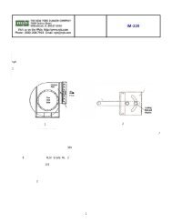
STANDARD AIR KITSF1"BWA M 2A M ABF6"F1"BAWMABF6"Dimensions in inches.B = wall thickness = 4” or 6”See page 15 for detail onF dimensions.Dimensions not to be usedfor construction unless certified.<strong>Double</strong><strong>Air</strong> Kit<strong>Single</strong><strong>Air</strong> KitBearing centersJShaftHBearing centersJShaftHDOUBLE AIR KITS SINGLE AIR KITSSize A F† MCHART VIIW H J Shaft diameterKeyways Bearings Shaft safe RPM ‡ Wheelsafe4” wall 6” wall 4” wall 6” wall 4” wall 6” wall Wheel Bearings4” wall 6” wall RPM ‡12B23-1 4 1 ⁄4 2 1 ⁄2 15 31 1 ⁄2 35 1 ⁄2 43 1 ⁄2 47 1 ⁄2 34 38 1 7 ⁄16 1 7 ⁄16 3⁄8 x 3 ⁄16 SPM* *218015B23-1 5 2 1 ⁄2 17 35 39 47 51 37 1 ⁄2 41 1 ⁄2 1 7 ⁄16 1 7 ⁄16 3⁄8 x 3 ⁄16 SPM* *178018B27-1 6 1 ⁄4 2 1 ⁄2 21 1 ⁄2 42 46 54 58 44 1 ⁄2 48 1 ⁄2 1 11 ⁄16 1 11 ⁄16 3⁄8 x 3 ⁄16 SPM* *147022B35-1 7 3 ⁄4 3 28 1 ⁄2 52 56 65 69 55 59 2 3 ⁄16 2 3 ⁄16 1⁄2 x 1 ⁄4 SPM* *120524B43-1 8 1 ⁄4 3 36 60 1 ⁄2 64 1 ⁄2 73 1 ⁄2 77 1 ⁄2 63 1 ⁄2 67 1 ⁄2 2 11 ⁄16 2 3 ⁄16 1⁄2 x 1 ⁄4 SPM* *109027B47-1 9 3 39 3 ⁄4 65 3 ⁄4 69 3 ⁄4 78 3 ⁄4 82 3 ⁄4 68 3 ⁄4 72 3 ⁄4 2 15 ⁄16 2 3 ⁄16 1⁄2 x 1 ⁄4 SPM* *99030B47-1 10 3 44 72 76 85 89 75 79 2 15 ⁄16 2 3 ⁄16 1⁄2 x 1 ⁄4 SPM* *89033B55-1 11 3 48 3 ⁄8 78 3 ⁄8 82 3 ⁄8 91 3 ⁄8 95 3 ⁄8 81 3 ⁄8 85 3 ⁄8 3 7 ⁄16 2 7 ⁄16 5⁄8 x 5 ⁄16 SPM* *81036B63-1 12 4 53 1 ⁄2 85 1 ⁄2 89 1 ⁄2 100 1 ⁄2 104 1 ⁄2 89 1 ⁄2 93 1 ⁄2 3 15 ⁄16 2 11 ⁄16 5⁄8 x 5 ⁄16 MPD* *73540B63-1 13 4 59 93 97 108 112 97 101 3 15 ⁄16 2 11 ⁄16 5⁄8 x 5 ⁄16 MPD* *66544B71-1 14 4 65 1 ⁄4 101 1 ⁄4 105 1 ⁄4 116 1 ⁄4 120 1 ⁄4 105 1 ⁄4 109 1 ⁄4 4 7 ⁄16 2 11 ⁄16 5⁄8 x 5 ⁄16 MPD* *60012B27-2 4 1 ⁄4 2 1 ⁄2 15 55 59 67 71 57 1 ⁄2 61 1 ⁄2 1 11 ⁄16 1 11 ⁄16 3⁄8 x 3 ⁄16 SPM 1210 1070 218012B35-2 4 1 ⁄4 3 15 55 59 68 72 58 62 2 3 ⁄16 2 3 ⁄16 1⁄2 x 1 ⁄4 SPM 1670 1480 218012B43-2 4 1 ⁄4 4 15 55 59 70 74 59 63 2 11 ⁄16 2 11 ⁄16 5⁄8 x 5 ⁄16 MPD 2260 2000 218015B31-2 5 2 1 ⁄2 17 62 66 74 78 64 1 ⁄2 68 1 ⁄2 1 15 ⁄16 1 15 ⁄16 1⁄2 x 1 ⁄4 SPM 1140 1025 178015B39-2 5 3 17 62 66 75 79 65 69 2 7 ⁄16 2 7 ⁄16 5⁄8 x 5 ⁄16 SPM 1555 1390 178015B47-2 5 3 17 62 66 75 79 65 69 2 15 ⁄16 2 3 ⁄16 1⁄2 x 1 ⁄4 SPM* *178018B35-2 6 1 ⁄4 3 21 1 ⁄2 76 80 89 93 79 83 2 3 ⁄16 2 3 ⁄16 1⁄2 x 1 ⁄4 SPM 810 740 147018B43-2 6 1 ⁄4 4 21 1 ⁄2 76 80 91 95 80 84 2 11 ⁄16 2 11 ⁄16 5⁄8 x 5 ⁄16 MPD 1110 1010 147018B55-2 6 1 ⁄4 3 21 1 ⁄2 76 80 89 93 79 83 3 7 ⁄16 2 7 ⁄16 5⁄8 x 5 ⁄16 SPM 1575 1435 147022B43-2 7 3 ⁄4 4 28 1 ⁄2 96 100 111 115 100 104 2 11 ⁄16 2 11 ⁄16 5⁄8 x 5 ⁄16 MPD 660 615 120522B47-2 7 3 ⁄4 3 28 1 ⁄2 96 100 109 113 99 103 2 15 ⁄16 2 3 ⁄16 1⁄2 x 1 ⁄4 SPM 675 625 120522B55-2 7 3 ⁄4 3 28 1 ⁄2 96 100 109 113 99 103 3 7 ⁄16 2 7 ⁄16 5⁄8 x 5 ⁄16 SPM 990 920 120522B63-2 7 3 ⁄4 4 28 1 ⁄2 96 100 111 115 100 104 3 15 ⁄16 2 11 ⁄16 5⁄8 x 5 ⁄16 MPD 1190 1100 120524B47-2 8 1 ⁄4 3 36 113 117 126 130 116 120 2 15 ⁄16 2 3 ⁄16 1⁄2 x 1 ⁄4 SPM 520 490 109024B55-2 8 1 ⁄4 3 36 113 117 126 130 116 120 3 7 ⁄16 2 7 ⁄16 5⁄8 x 5 ⁄16 SPM 670 630 109024B63-2 8 1 ⁄4 4 36 113 117 128 132 117 121 3 15 ⁄16 2 11 ⁄16 5⁄8 x 5 ⁄16 MPD 815 765 109024B71-2 8 1 ⁄4 4 36 113 117 128 132 117 121 4 7 ⁄16 2 11 ⁄16 5⁄8 x 5 ⁄16 MPD 970 910 109024B79-2 8 1 ⁄4 4 1 ⁄2 36 113 117 129 133 117 1 ⁄2 121 1 ⁄2 4 15 ⁄16 2 15 ⁄16 3⁄4 x 3 ⁄8 MPD 1100 1030 109027B47-2 9 3 39 3 ⁄4 123 1 ⁄2 127 1 ⁄2 136 1 ⁄2 140 1 ⁄2 126 1 ⁄2 130 1 ⁄2 2 15 ⁄16 2 3 ⁄16 1⁄2 x 1 ⁄4 SPM 420 395 99027B55-2 9 3 39 3 ⁄4 123 1 ⁄2 127 1 ⁄2 136 1 ⁄2 140 1 ⁄2 126 1 ⁄2 130 1 ⁄2 3 7 ⁄16 2 7 ⁄16 5⁄8 x 5 ⁄16 SPM 540 510 99027B63-2 9 4 39 3 ⁄4 123 1 ⁄2 127 1 ⁄2 138 1 ⁄2 142 1 ⁄2 127 1 ⁄2 131 1 ⁄2 3 15 ⁄16 2 11 ⁄16 5⁄8 x 5 ⁄16 MPD 660 625 99027B71-2 9 4 39 3 ⁄4 123 1 ⁄2 127 1 ⁄2 138 1 ⁄2 142 1 ⁄2 127 1 ⁄2 131 1 ⁄2 4 7 ⁄16 2 11 ⁄16 5⁄8 x 5 ⁄16 MPD 790 745 99027B79-2 9 4 1 ⁄2 39 3 ⁄4 123 1 ⁄2 127 1 ⁄2 139 1 ⁄2 143 1 ⁄2 128 132 4 15 ⁄16 2 15 ⁄16 3⁄4 x 3 ⁄8 MPD 905 855 99027B87-2 9 4 1 ⁄2 39 3 ⁄4 123 1 ⁄2 127 1 ⁄2 139 1 ⁄2 143 1 ⁄2 128 132 5 7 ⁄16 2 15 ⁄16 3⁄4 x 3 ⁄8 MPD 1035 975 99030B55-2 10 3 44 136 140 149 153 139 143 3 7 ⁄16 2 7 ⁄16 5⁄8 x 5 ⁄16 SPM 425 400 89030B63-2 10 4 44 136 140 151 155 140 144 3 15 ⁄16 2 11 ⁄16 5⁄8 x 5 ⁄16 MPD 520 495 89030B71-2 10 4 44 136 140 151 155 140 144 4 7 ⁄16 2 11 ⁄16 5⁄8 x 5 ⁄16 MPD 625 595 89030B79-2 10 4 1 ⁄2 44 136 140 152 156 140 1 ⁄2 144 1 ⁄2 4 15 ⁄16 2 15 ⁄16 3⁄4 x 3 ⁄8 MPD 720 685 89030B87-2 10 4 1 ⁄2 44 136 140 152 156 140 1 ⁄2 144 1 ⁄2 5 7 ⁄16 2 15 ⁄16 3⁄4 x 3 ⁄8 MPD 820 785 89033B63-2 11 4 48 3 ⁄8 148 3 ⁄4 152 3 ⁄4 163 3 ⁄4 167 3 ⁄4 152 3 ⁄4 156 3 ⁄4 3 15 ⁄16 2 11 ⁄16 5⁄8 x 5 ⁄16 MPD 430 410 81033B71-2 11 4 48 3 ⁄8 148 3 ⁄4 152 3 ⁄4 163 3 ⁄4 167 3 ⁄4 152 3 ⁄4 156 3 ⁄4 4 7 ⁄16 2 11 ⁄16 5⁄8 x 5 ⁄16 MPD 520 495 81033B79-2 11 4 1 ⁄2 48 3 ⁄8 148 3 ⁄4 152 3 ⁄4 164 3 ⁄4 168 3 ⁄4 153 1 ⁄4 157 1 ⁄4 4 15 ⁄16 2 15 ⁄16 3⁄4 x 3 ⁄8 MPD 600 575 81033B87-2 11 4 1 ⁄2 48 3 ⁄8 148 3 ⁄4 152 3 ⁄4 164 3 ⁄4 168 3 ⁄4 153 1 ⁄4 157 1 ⁄4 5 7 ⁄16 2 15 ⁄16 3⁄4 x 3 ⁄8 MPD 690 655 810† F dimensions shown in detail on page 15. Safe speed of shaft exceeds safe speed of wheel. ‡ Safe speeds are given at 70°F. See Chart VI, page 5, for temperature correction.*PAGE 10
NON-STANDARD AIR KITSWhen the system plenum cannot be designedto accommodate pre-designed, st<strong>and</strong>ard <strong>Air</strong><strong>Kits</strong> [from Chart VII], <strong>Air</strong> <strong>Kits</strong> with nonst<strong>and</strong>ardshaft sizes <strong>and</strong> wheel bores may beselected using the shaft safe speed curves onpages 11 to 14.F1"BWA M 2A M ABFKF1"BAWMABFKThe curves show maximum shaft safe speedsat 70°F. for all possible bearing-center distances<strong>and</strong> <strong>Air</strong> Kit combinations. Final selectionsmust be corrected for operating temperature.Curves are based on proper spacing of fansbetween walls [A on each side <strong>and</strong> 2A betweenfans]. Curves cannot be extended to obtainselections not shown.Bearing centersJHShaft<strong>Double</strong> <strong>Air</strong> KitBearing centersJShaftH<strong>Single</strong> <strong>Air</strong> KitSee page 4 for A dimension criteria.See page 15 for F, K, <strong>and</strong> M dimension criteria.HOW TO SELECT A NON-STANDARD AIR KITPROCEDURES STEPS EXAMPLESummary.<strong>Air</strong> Kit size <strong>and</strong> model have been selected from the example on page 6.Plenum effect has been calculated <strong>and</strong> speed <strong>and</strong> BHP determined. Wheelsafe speed at 700°F had been checked.Calculate bearing-center distance.Select shaft size <strong>and</strong> check shaftsafe speed at operating temperature.Final selection.Inside wall-to-wall distance is 54”. Wall thickness is 4” for a total W of 62”.Use F dimension from Chart VII for <strong>Double</strong> <strong>Air</strong> Kit with closest W dimension.F = 3”. Bearing centers for using curves is 65”.Using the X15B-2 graph, draw a horizon line from 65” <strong>and</strong> a vertical line from1197 RPM. Correct selection is the curve that is above the intersection point...15B35-2 with a maximum safe speed of 1310 at 70°F. [continue the horizontalline], 1310 x .92 [Chart VI @700°F.] = 1205 RPM.An X15B35-2 <strong>Air</strong> Kit with cooler wheels.120X12B-1 SINGLE AIR KIT120X12B-2 DOUBLE AIR KIT110110Bearing centers [Inches]10090807060504012B47-112B43-112B39-112B35-112B31-112B27-112B23-1Bearing centers [Inches]1009080706012B23-212B27-212B31-212B35-212B47-212B43-212B39-2305020400 500 600 700 800 900 1000 1100 1200 1300 1400 1500 1600 1700 1800 1900 2000 2100 2200Shaft safe speed [RPM]40400 500 600 700 800 900 1000 1100 1200 1300 1400 1500 1600 1700 1800 1900 2000 2100 2200Shaft safe speed [RPM]PAGE 11
NON-STANDARD AIR KITS120X15B-1 SINGLE AIR KIT120X15B-2 DOUBLE AIR KIT110100110Bearing centers [Inches]908070605015B35-115B31-115B23-115B47-115B43-115B39-115B27-1Bearing centers [Inches]10090807015B27-215B31-215B39-215B35-215B47-215B43-240306015B23-220300 400 500 600 700 800 900 1000 1100 1200 1300 1400 1500 1600 1700 1800Shaft safe speed [RPM]50300 400 500 600 700 800 900 1000 1100 1200 1300 1400 1500 1600 1700 1800Shaft safe speed [RPM]130X18B-1 SINGLE AIR KIT130X18B-2 DOUBLE AIR KIT120110120Bearing centers [Inches]1009080706018B63-118B55-118B47-118B43-118B39-118B35-118B31-118B27-1Bearing centers [Inches]110100908018B31-218B35-218B39-218B43-218B47-218B63-218B55-250407018B27-230200 300 400 500 600 700 800 900 1000 1100 1200 1300 1400 1500Shaft safe speed [RPM]60200 300 400 500 600 700 800 900 1000 1100 1200 1300 1400 1500Shaft safe speed [RPM]130X22B-1 SINGLE AIR KIT130X22B-2 DOUBLE AIR KIT12011022B63-1120Bearing centers [Inches]10090807022B35-122B31-122B43-122B39-122B55-122B47-1Bearing centers [Inches]11010022B43-222B47-222B55-222B63-222B39-222B31-222B35-26022B27-1905040200 300 400 500 600 700 800 900 1000 1100 1200 1300Shaft safe speed [RPM]80200 300 400 500 600 700 800 900 1000 1100 1200 1300Shaft safe speed [RPM]PAGE 12
NON-STANDARD AIR KITS130X24B-1 SINGLE AIR KIT130X24B-2 DOUBLE AIR KIT12024B71-112511024B63-1Bearing centers [Inches]100908024B47-124B43-124B39-124B55-1Bearing centers [Inches]12011511024B43-224B47-224B55-224B63-224B71-2706010550300 400 500 600 700 800 900 1000 1100Shaft safe speed [RPM]100300 400 500 600 700 800 900 1000 1100Shaft safe speed [RPM]130X27B-1 SINGLE AIR KIT130X27B-2 DOUBLE AIR KIT12027B71-1Bearing centers [Inches]110100908027B43-127B39-127B47-127B55-127B63-1Bearing centers [Inches]12512011527B43-227B47-227B55-227B63-227B71 -27060200 300 400 500 600 700 800 900 1000Shaft safe speed [RPM]110200 300 400 500 600 700 800 900 1000Shaft safe speed [RPM]140X30B-1 SINGLE AIR KIT140X30B-2 DOUBLE AIR KIT13030B79-130B87-212030B71-1135Bearing centers [Inches]110100908030B47-130B43-130B63-130B55-1Bearing centers [Inches]13012530B63-230B71-230B79-230B55-27060300 400 500 600 700 800 900Shaft safe speed [RPM]120400 450 500 550 600 650 700 750 800 850 900Shaft safe speed [RPM]PAGE 13
NON-STANDARD AIR KITS140X33B-1 SINGLE AIR KIT33B79-1180X33B-2 DOUBLE AIR KIT13033B73-1170Bearing centers [Inches]1201101009033B47-133B43-133B55-133B63-1Bearing centers [Inches]16015033B79-233B87-233B96-28014033B63-233B71-270300 400 500 600 700 800 900Shaft safe speed [RPM]130300 400 500 600 700 800 900Shaft safe speed [RPM]170X36B-1 SINGLE AIR KIT180X40B-1 SINGLE AIR KIT16036B96-117040B96-115036B87-116040B87-1Bearing centers [Inches]14013012011010036B63-136B55-136B79-136B71-1Bearing centers [Inches]15014013012011010040B63-140B55-140B79-140B71-1909080300 400 500 600 700 800Shaft safe speed [RPM]80300 400 500 600 700Shaft safe speed [RPM]180170X44B-1 SINGLE AIR KIT44B96-1SPECIFICATIONSSTANDARD SHEET GAUGE, WHEEL WEIGHTS [RPM]Bearing centers [Inches]16015014013012011010044B55-144B79-144B71-144B63-144B87-19080300 350 400 450500 550 600Shaft safe speed [RPM]SizeHousingWheelSide ScrollBack Frontplate plateBladesWeightInletcone12 16 16 14 14 18 24 —15 14 14 14 14 18 29 —18 14 14 12 14 18 50 —22 14 14 12 14 18 100 —24 11 12 10 12 16 151 1627 11 12 10 10 16 185 1630 11 12 7 10 16 235 1433 10 12 7 10 16 268 1436 10 10 7 10 12 565 1440 10 10 7 10 12 652 1444 10 10 1 ⁄4 7 12 816 14PAGE 14
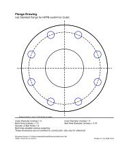
DRAWINGS/DIMENSIONS [INCHES] Not to be used for construction unless certified.HOUSINGSBEARINGSMBCSIZES12-22WDDDGGAHEFESizeBC D DD E G M W12 11 1 ⁄2 10 1 ⁄8 15 12 1 ⁄2 7 1 ⁄4 8 7 ⁄8 15 12 1 ⁄415 13 1 ⁄2 12 7 ⁄8 17 15 1 ⁄8 9 1 ⁄4 11 1 ⁄8 17 1518 14 16 1 ⁄4 21 1 ⁄2 18 1 ⁄2 11 1 ⁄2 13 7 ⁄8 21 1 ⁄2 18 1 ⁄422 18 1 ⁄2 19 5 ⁄8 25 1 ⁄4 22 1 ⁄2 14 1 ⁄8 16 7 ⁄8 28 1 ⁄2 24 1 ⁄2SIZES24-44MWDGBECShaftsizeBearingtypeCBA B C D E F G H1 7 ⁄16 SPM 2 3 ⁄8 8 1 ⁄4 6 1 ⁄4 2 1 ⁄4 1 1 ⁄4 3⁄4 3⁄4 4 1 ⁄21 11 ⁄16 SPM 2 3 ⁄8 8 3 ⁄4 6 1 ⁄2 2 3 ⁄8 1 1 ⁄4 3⁄4 3⁄4 4 5 ⁄82 3 ⁄16 SPM 3 1 ⁄8 11 1 ⁄4 8 1 ⁄2 2 3 ⁄4 1 1 ⁄2 3⁄4 7⁄8 5 15 ⁄162 7 ⁄16 SPM 3 1 ⁄8 11 1 ⁄2 8 5 ⁄8 3 1 1 ⁄2 7⁄8 7⁄8 6 1 ⁄162 11 ⁄16 MPD 3 1 ⁄2 13 9 3 1 ⁄2 2 15 ⁄16 1 1 ⁄8 72 15 ⁄16 MPD 3 1 ⁄2 13 9 3 1 ⁄2 2 15 ⁄16 1 1 ⁄4 7 1 ⁄4TYPICAL BEARING MOUNTING DETAILWheel/cone gap must be largeenough to account for shaft expansionDSizeBC D E G M WStudcircleInlet cone24 18 3 ⁄4 21 3 ⁄4 25 15 1 ⁄2 18 5 ⁄8 36 26 7 ⁄8 29 1 ⁄827 20 3 ⁄4 24 27 1 ⁄2 17 1 ⁄4 20 5 ⁄8 39 3 ⁄4 29 5 ⁄8 31 3 ⁄430 23 26 5 ⁄8 30 1 ⁄2 19 1 ⁄8 22 7 ⁄8 44 33 35 1 ⁄833 25 1 ⁄2 29 1 ⁄2 33 3 ⁄4 21 1 ⁄4 25 3 ⁄8 48 3 ⁄8 36 1 ⁄4 38 3 ⁄836 28 1 ⁄4 32 5 ⁄8 37 3 ⁄8 23 5 ⁄8 28 1 ⁄8 53 1 ⁄2 39 7 ⁄8 42 3 ⁄840 31 1 ⁄8 36 41 1 ⁄8 26 31 59 43 7 ⁄8 46 1 ⁄844 34 3 ⁄8 39 3 ⁄4 45 1 ⁄2 28 3 ⁄4 34 1 ⁄4 65 1 ⁄4 48 5 ⁄8 51 1 ⁄8Plenum wallShaft-cooler guardShaft-cooler wheelKF1/ 2"Tolerance: ± 1 ⁄8”SHAFT COOLERSCExpansionbearingShaftcoolerconeHousingWheelFixedbearingTurndown 1" insideShaftcoolerplenum wallconeD B AEGap must be large enough so thatturndown does not contactbearing after expansion6- 1 / 2" diameter holesBore* A B C D E1 - 2 3 ⁄16 14 12 3 ⁄4 2 1 ⁄4 11 2 3 ⁄42 7 ⁄16 - 2 15 ⁄16 18 3 ⁄8 17 1 ⁄8 3 1 ⁄8 15 1 ⁄4 3 3 ⁄43 7 ⁄16 - 3 15 ⁄16 23 1 ⁄8 21 7 ⁄8 3 1 ⁄2 20 4 1 ⁄24 7 ⁄16 - 5 7 ⁄16 25 5 ⁄8 24 3 ⁄8 3 3 ⁄4 22 1 ⁄2 5 1 ⁄2* Shaft-cooler bore should be same as wheel bore.Tolerance: ± 1 ⁄8”Optional preselected bearings are available with nyb <strong>Air</strong> <strong>Kits</strong>.However, it is recognized that some customers may have bearingspecifications other than available through nyb. The detail shownhere provides dimension information <strong>and</strong> a suitable method of construction.The F dimensions for St<strong>and</strong>ard <strong>Air</strong> <strong>Kits</strong> are given in Chart VII,page 10.F = Nominal width of bearing bar.K = Shaft extension for drive is based on placing sheave as close tobearing bar as possible. Speeds in Chart VII <strong>and</strong> on curvespages 11-14 are based on 1 ⁄2” maximum.PAGE 15
COMPLETE SELECTION OFAIR-MOVING EQUIPMENTThe <strong>New</strong> <strong>York</strong> <strong>Blower</strong> Company offersthous<strong>and</strong>s of different types, models, <strong>and</strong>sizes of air-moving equipment. Contactyour nyb representative for assistance inidentifying the best fan for your application.AIR-HANDLING[AXIAL]For the ideal h<strong>and</strong>ling of cleanto moderately dirty airstreams.Commercial <strong>and</strong> industrial HVAC,drying <strong>and</strong> cooling systems, fumeextraction, <strong>and</strong> process-heatremoval are typical applications.FIBERGLASSREINFORCEDPLASTIC [FRP]Choice of performance <strong>and</strong> duty forcorrosive gas streams. Applicationsinclude chemical process, wastewatertreatment, laboratory hood exhaust,<strong>and</strong> tank aeration.DUST/MATERIALHANDLINGWide range of duty availablewith unique fan lines capableof h<strong>and</strong>ling light dust to heavymaterial. Typical applicationsinclude dust-collection <strong>and</strong>high-pressure process alongwith material-conveying.AIR-HANDLING[CENTRIFUGAL]Designed for clean to moderatelydirty gas streams. Commercial<strong>and</strong> industrial HVAC, processcooling, light material-conveying,heat removal, <strong>and</strong> dryer exhaustare just a few of the numeroussample applicationsCUSTOM PRODUCTSDesigned for unique applications. Variety of configurations,temperatures, flows, <strong>and</strong> pressures. Wide range ofmodifications <strong>and</strong>accessories areavailable tomeet the mostdem<strong>and</strong>ingspecifications.Leading the industry forward since 1889ROOF VENTILATORSIncluding both hooded <strong>and</strong> upblast ventilators,propeller fans, <strong>and</strong> centrifugal roof exhausters.These units are ideal for industrial, commercial,<strong>and</strong> institutional applications.HEATINGPRODUCTSIndustrial-duty steamunit heaters with steamheating coils are availablefor facility heating <strong>and</strong>process-heat transfer.PROCESS/FANCOMPONENTSPlug fans, plenum fans, wheels, inlet cones,<strong>and</strong> housings for a wide variety of OEMapplications. Process/fan components areused in air-h<strong>and</strong>ling units, ovens, dryers,freezer tunnels, <strong>and</strong> filtration systems.