CW-S-0001 - STI - Specified Technologies Inc
CW-S-0001 - STI - Specified Technologies Inc
CW-S-0001 - STI - Specified Technologies Inc

Create successful ePaper yourself
Turn your PDF publications into a flip-book with our unique Google optimized e-Paper software.
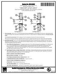
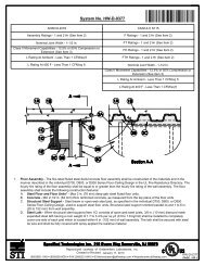
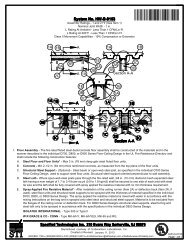
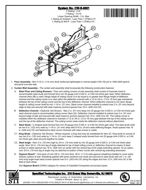
F Rating - 2 Hr<br />
T Rating - 1/2 Hr<br />
Linear Opening Width - 2 In. Max<br />
L Rating At Ambient - Less Than 1 CFM/Lin Ft<br />
L Rating At 400°F - Less Than 1 CFM/Lin Ft<br />
Ì89<strong>CW</strong>SÇÂ!ÈAOÇ#--lÎ<br />
2C<br />
2G<br />
2C<br />
2F<br />
3B<br />
2A<br />
3C<br />
2E<br />
3C<br />
1<br />
2A<br />
2H<br />
2D<br />
2E<br />
2G<br />
1. Floor Assembly - Min 4-1/2 in. (114 mm) thick reinforced lightweight or normal weight (100-150 pcf or 1600-2400 kg/m3)<br />
structural concrete slab.<br />
2. Curtain Wall Assembly - The curtain wall assembly shall incorporate the following construction features:<br />
A. Steel Floor and Ceiling Runners - Floor and ceiling runners of wall assembly shall consist of channels sized to<br />
accommodate steel studs and formed from min 25 gauge (min 0.025 in. or 0.64 mm thick) galv steel. When deflection<br />
channel (Item 2B) is used, flange height of ceiling runner is to be equal to or greater than flange height of deflection<br />
channel and the ceiling runner is to nest within the deflection channel with a 1/2 to 3/4 in. (13 to 19 mm) gap maintained<br />
between the top of the ceiling runner and the top of the deflection channel. When deflection channel is not used, flange<br />
height of ceiling runner shall be min 1-1/4 in. (31 mm). Steel runner channel installed to extend max 2 in. (51 mm) beyond<br />
edge of slab and secured with steel masonry anchors spaced max 16 in. (406 mm) OC.<br />
B. Deflection Channel - (Optional, Not Shown) - Max 2 in. (51 mm) deep min 25 gauge (min 0.025 in. or 0.64 mm thick) galv<br />
steel channel sized to accommodate ceiling runner (Item 2A). Deflection channel installed to extend max 2 in. (51 mm)<br />
beyond edge of slab and secured with steel masonry anchors spaced max 16 in. (406 mm) OC. The ceiling runner is<br />
installed within the deflection channel to maintain a 1/2 to 3/4 in. (13 to 19 mm) gap between the top of the ceiling runner<br />
and the top of the deflection channel. The ceiling runner nests inside the deflection channel without attachment.<br />
C. Steel Studs - C-shaped studs formed from min 25 gauge (min 0.025 in. or 0.64 mm thick) galv steel. The steel studs shall<br />
be min 6 in. (152 mm) wide by 1-1/4 in. (31 mm) deep with 5/16 in. (8 mm) wide stiffening flanges. Studs spaced max 16<br />
in. (406 mm) OC and fastened to steel runner channels with steel screws or welds.<br />
C1. King Studs - (Optional, Not Shown) - Where required, a king stud may be substituted for Item 2C. King studs to consist of<br />
two min 6 in. (152 mm) wide by 1-1/4 in. (31 mm) deep C-shaped studs formed from min 25 gauge (min 0.025 in. or 0.64<br />
mm thick) galv steel secured together by welds.<br />
C2. Steel Angle - Nom 3 in. (76 mm) high by 3/4 in. (19 mm) wide by min 25 gauge (min 0.025 in. or 0.64 mm thick) steel<br />
angle. Nom 3/4 in. (19 mm) leg of angle attached to top of steel ceiling runner or deflection channel by means of steel<br />
screws or welds spaced max 16 in. (406 mm) on center with the vertical leg of the angle extending upward. As an option,<br />
nom 3/4 in. (19 mm) leg of angle may be attached to bottom of floor runner with vertical leg extending downward.<br />
D. Gypsum Board* - One layer of nom 5/8 in. (16 mm) thick, 48 in. (1.2 m) wide gypsum sheathing installed to cover entire<br />
exterior surface of wall. Sheathing applied with joints centered over studs and secured to steel studs with min 1 in. (25<br />
mm) long bugle head steel screws spaced max 8 in. (203 mm) OC along the edges and max 12 in. (305 mm) OC in the<br />
field of each sheet.<br />
See Gypsum Board (CKNX) category for names of Classified Companies and product types.<br />
Reproduced courtesy of Underwriters Laboratories, <strong>Inc</strong>.<br />
Created or Revised: March 13, 2013<br />
(800)992-1180 (908)526-8000 FAX (908)231-8415 E-Mail:techserv@stifirestop.com Website:www.stifirestop.com<br />
R<br />
<strong>CW</strong>-S-<strong>0001</strong><br />
PAGE 1 OF 2
D1. Cementitious Backer Units* - As an alternate to the gypsum sheathing (Item 2D), nom 1/2 in. or 5/8 in. (13 or 16 mm)<br />
thick square-edge boards attached to studs with 1-1/4 in. (31 mm) long corrosion resistant self-tapping wafer-head steel<br />
screws spaced 6 in. (152 mm) OC. Joints covered with glass fiber mesh tape.<br />
UNITED STATES GYPSUM CO - Type DCB<br />
D2. Joint Opening - (Not Shown)- As an option in Items 2D and 2D1, a max 3/4 in. (19 mm) wide horizontal joint backed by<br />
deflection channel (Item 2B) may be included. The top edge of the horizontal joint shall align with the bottom edge of the<br />
concrete floor slab. Horizontal joint opening in Item 2D or 2D1 sealed with nom 1/2 in. (13 mm) thickness of sealant ( Fill,<br />
Void or Cavity Material*) over optional foam backer rod.<br />
SPECIFIED TECHNOLOGIES INC - Pensil 300 Sealant or SpecSeal Series SIL300 Sealant<br />
E. Batts and Blankets* - Any glass fiber insulation bearing the UL Classification Marking as to fire resistance or surface<br />
burning characteristics, of a width and thickness to completely fill stud cavity. Insulation batts friction fit to completely fill all<br />
stud cavities of curtain wall above the top of the fill material (Item 3B) and below the forming material (Item 3A).<br />
See Batts and Blankets (BZJZ) category for names of manufacturers.<br />
F. Gypsum Board* - One layer of nom 5/8 in. (16 mm) thick, 48 in. (1.2 m) wide gypsum board applied with joints centered<br />
over studs. Gypsum board secured to steel studs on interior surface of curtain wall with min 1 in. (25 mm) long bugle head<br />
steel screws spaced max 8 in. (203 mm) OC along the edges and max 12 in. (305 mm) OC in the field of each sheet.<br />
Gypsum board installed to cover interior surface of wall above the top of the fill material (Item 3C) for a min distance of<br />
4-1/2 in. (114 mm). Gypsum board is optional below floor assembly.<br />
See Gypsum Board (CKNX) category for names of Classified Companies and product types.<br />
G. Framed Window - Metal-framed window with nom 1 in. (25 mm) thick (double pane) transparent heat-strengthened or<br />
tempered glass panels. Sill of window to be min 4-1/2 in. (114 mm) above top of floor slab. Vertical separation between<br />
window punch-outs to be min 36 in. (914 mm). Top of window to be min 24 in. (610 mm) below bottom of floor slab.<br />
H. Exterior Insulation and Finish System (EIFS) - Nom 2 in. (51 mm) thick extruded polystyrene Foamed Plastic*<br />
insulation bearing the UL Classification Marking, attached over sheathing and finished with coating system, or Portland<br />
cement or synthetic stucco systems, in accordance with manufacturer's instructions.<br />
See Foamed Plastic (BRYX or CCVW) category for names of Classified companies.<br />
I. Siding, Brick or Stucco - (Not Shown) - Aluminum siding, steel siding, brick veneer or stucco installed over gypsum<br />
sheathing or cementitious backer units and meeting the requirements of local code agencies. Brick veneer wall attached to<br />
studs with corrugated metal wall ties attached to each stud with steel screws.<br />
J. Glass Fiber Reinforced Concrete (GFRC) Panels - (Not Shown) - Min 1/2 in. (13 mm) thick glass fiber reinforced<br />
concrete (GFRC) panels installed over gypsum sheathing or cementitious backer units and meeting the requirements of<br />
local code agencies.<br />
3. Safing System - The safing system shall incorporate the following construction features:<br />
A. Impaling Pins - (Optional, Not Shown) - No. 12 gauge steel pins swaged to nom 2 by 2 in. (51 by 51 mm) galv steel base<br />
plate. Steel base plates secured to edge of concrete slab by means of min 1 in. (25 mm) long steel concrete screws.<br />
Impaling pins to be spaced max 16 in. (406 mm) on center.<br />
B. Forming Material* - Nom 4 pcf (64 kg/m3) density mineral wool batt insulation. Batt sections to be cut to a min width<br />
equal to thickness of floor assembly and stacked to a thickness which is 25 percent greater than the width of linear gap<br />
between the gypsum sheathing and the edge of the concrete floor to attain a min 20 percent compression in the thickness<br />
direction when installed. The forming material is installed cut-edge-first into linear gap between edge of floor slab, steel<br />
angle (Item 2C2) and sheathing material such that its top surface is flush with the top surface of the floor assembly. As an<br />
option when Item 3A is used, the batt sections can be impaled on 12 AWG pins and secured by means of nom 1-1/2 in.<br />
(38 mm) diam steel clinch shields. As an alternate to the optional impaling pin, when the steel angle is fastened to the<br />
bottom of the steel floor runner, a steel screw may be driven through the steel angle and safing insulation against the floor<br />
slab to secure batt sections.<br />
THERMAFIBER INC - SAF<br />
C. Fill, Void or Cavity Material* - Spray - Min 1/8 in. (3.2 mm) wet thickness (min 1/16 in. or 1.6 mm dry thickness) of fill<br />
material spray-applied at interface of steel floor runner and gypsum sheathing with min 1/2 in. (13 mm) overlap and at<br />
interface of steel floor runner and concrete floor with min 1/2 in. (13 mm) overlap.<br />
SPECIFIED TECHNOLOGIES INC - SpecSeal AS200 Elastomeric Spray or SpecSeal Fast Tack Spray<br />
*Bearing the UL Classification Mark<br />
Reproduced courtesy of Underwriters Laboratories, <strong>Inc</strong>.<br />
Created or Revised: March 13, 2013<br />
(800)992-1180 (908)526-8000 FAX (908)231-8415 E-Mail:techserv@stifirestop.com Website:www.stifirestop.com<br />
R<br />
<strong>CW</strong>-S-<strong>0001</strong><br />
PAGE 2OF<br />
2