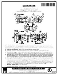
HW-D-0088 - STI - Specified Technologies Inc
HW-D-0088 - STI - Specified Technologies Inc
HW-D-0088 - STI - Specified Technologies Inc

Create successful ePaper yourself
Turn your PDF publications into a flip-book with our unique Google optimized e-Paper software.
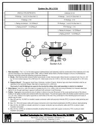
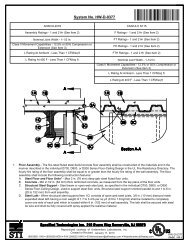
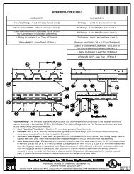
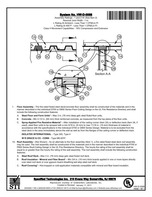
Assembly Ratings - 1 and 2 Hr (See Item 2)<br />
Nominal Joint Width - 1 in.<br />
L Rating At Ambient - Less Than 1 CFM/Lin Ft<br />
L Rating At 400°F - Less Than 1 CFM/Lin Ft<br />
Class II Movement Capabilities - 19% Compression and Extension<br />
Ì74<strong>HW</strong>DÇÂxÈAOÇ!+-=Î<br />
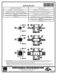
1A<br />
1B<br />
A<br />
1B<br />
3B<br />
3C<br />
1C<br />
A<br />
1C<br />
2C<br />
2A<br />
2C<br />
1A<br />
1B<br />
1A<br />
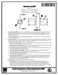
Section A-A<br />
2B<br />
1C<br />
3B<br />
2B<br />
2A<br />
2C<br />
3C<br />
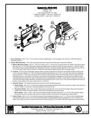
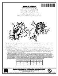
1. Floor Assembly - The fire-rated fluted steel deck/concrete floor assembly shall be constructed of the materials and in the<br />
manner described in the individual D700 or D800 Series Floor-Ceiling Design in the UL Fire Resistance Directory and shall<br />
include the following construction features:<br />
A. Steel Floor and Form Units* - Max 3 in. (76 mm) deep galv steel fluted floor units.<br />
B. Concrete - Min 2-1/2 in. (64 mm) thick reinforced concrete, as measured from the top plane of the floor units.<br />
C. Spray-Applied Fire Resistive Material* - After installation of the ceiling runner (Item 2A) or deflection track (Item 3A, if<br />
used), steel floor units to be sprayed with a min 5/16 in. (8 mm) to max 11/16 in. (18 mm) thickness of material in<br />
accordance with the specifications in the individual D700 or D800 Series Design. Material is to be excluded from the<br />
steel deck in the area immediately above the wall as well as from the flanges of the ceiling runner or deflection track.<br />
ISOLATEK INTERNATIONAL - Type 300, Type II<br />
W R GRACE & CO - CONN - Type MK-6/HY<br />
1A. Roof Assembly - (Not Shown) - As an alternate to the floor assembly (Item 1), a fire rated fluted steel deck roof assembly<br />
may be used. The roof assembly shall be constructed of the materials and in the manner described in the individual P700 or<br />
P800 Series Roof-Ceiling Design in the UL Fire Resistance Directory. The hourly fire rating of the roof assembly shall be<br />
equal to or greater than the hourly fire rating of the wall assembly. The roof assembly shall include the following construction<br />
features:<br />
A. Steel Roof Deck - Max 3 in. (76 mm) deep galv steel fluted roof deck.<br />
B. Roof Insulation - Mineral and Fiber Board* - Min 3/4 in. (19 mm) thick boards applied in one or more layers directly<br />
over steel roof deck or over gypsum board sheathing laid atop steel roof deck.<br />
C. Roof Covering* - Hot-mopped or cold-application materials compatible with mineral and fiber board insulation.<br />
Reproduced courtesy of Underwriters Laboratories, <strong>Inc</strong>.<br />
Created or Revised: January 11, 2011<br />
(800)992-1180 (908)526-8000 FAX (908)231-8415 E-Mail:techserv@stifirestop.com Website:www.stifirestop.com<br />
R<br />
<strong>HW</strong>-D-<strong>0088</strong><br />
PAGE 1 OF 3
D. Spray-Applied Fire Resistive Material* - After installation of the ceiling runner (Item 2A) or deflection track (Item 3A, if<br />
used), steel roof deck to be sprayed with a max 3/4 in. (19 mm) thickness of spray applied fire resistive material as<br />
specified in the individual P700 or P800 Series Roof-Ceiling design. Material is to be excluded from the steel deck in the<br />
area immediately above the wall as well as from the flanges of the ceiling runner or deflection track.<br />
ISOLATEK INTERNATIONAL - Type 300, Type II<br />
W R GRACE & CO - CONN - Type MK-6/HY<br />
2. Wall Assembly - The 1 or 2 hr fire-rated gypsum board/stud wall assembly shall be constructed of the materials and in the<br />
manner described in the individual U400 or V400 Series Wall and Partition Design in the UL Fire Resistance Directory and<br />
shall include the following construction features:<br />
A. Steel Floor and Ceiling Runners - Floor and ceiling runners of wall assembly shall consist of galv steel channels sized<br />
to accommodate steel studs . Ceiling runner to be provided with min 1-1/4 in. (32 mm) to max 2 in. (51 mm) flanges.<br />
When deflection channel (Item 3A) is used, flange height of ceiling runner is to be equal to or greater than flange height<br />
of deflection channel and the ceiling runner is to nest within the deflection channel with a 1/2 in. (13 mm) to 3/4 in. (19<br />
mm) gap maintained between the top of the ceiling runner and the top of the deflection channel. When deflection channel<br />
is not used, ceiling runner installed perpendicular to direction of fluted steel deck prior to the application of spray-applied<br />
fire resistive material and secured to valleys with steel masonry anchors or welds spaced max 24 in. (610 mm) OC.<br />
A1. Light Gauge Framing* - Slotted Ceiling Runner - As an alternate to the ceiling runner in Item 2A, ceiling runner to<br />
consist of galv steel channel with slotted flanges sized to accommodate steel studs (Items 2B). Slotted ceiling runner<br />
installed perpendicular to direction of fluted steel deck prior to the application of spray-applied fire resistive material and<br />
secured to valleys with steel masonry anchors spaced max 24 in. (610 mm) OC. When slotted ceiling runner is used,<br />
deflection channel (Item 3A) shall not be used.<br />
BRADY CONSTRUCTION INNOVATIONS INC, DBA SLIPTRACK SYSTEMS - SLP-TRK<br />
CALIFORNIA EXPANDED METAL PRODUCTS CO - CST<br />
CLARKDIETRICH BUILDING SYSTEMS - Type SLT, SLT-H<br />
MARINO/WARE, DIV OF WARE INDUSTRIES INC - Type SLT<br />
METAL-LITE INC - The System<br />
SCAFCO STEEL STUD MANUFACTURING CO<br />
STEELER INC - Steeler Slotted Ceiling Runner<br />
TELLING INDUSTRIES L L C - True-Action Deflection Track<br />
THE STEEL NETWORK INC - VertiTrack VT, series,250VT, 362VT, 400VT, 600VT and 800VT<br />
A2. Light Gauge Framing* - Notched Ceiling Runner - As an alternate to the ceiling runners in Items 2A through 2A2,<br />
notched ceiling runners to consist of C-shaped galv steel channel with notched return flanges sized to accommodate<br />
steel studs (Item 2B). Notched ceiling runner installed perpendicular to direction of fluted steel floor deck prior to the<br />
application of spray-applied fire resistive material and secured to valleys with steel masonry anchors spaced max 24 in.<br />
OC. When notched ceiling runner is used, deflection channel (Item 3A) shall not be used.<br />
OLMAR SUPPLY INC - Type SCR<br />
B. Studs - Steel studs to be min 3-1/2 in. (89 mm) wide. Studs cut 1/2 in. (13 mm) to 3/4 in. (19 mm) less in length than<br />
assembly height with bottom nesting in and secured to floor runner. When slotted ceiling runner (Item 2A1) is used, steel<br />
studs secured to slotted ceiling runner with No. 8 by 1/2 in. (13 mm) long wafer head steel screws at midheight of slot on<br />
each side of wall. When deflection channel (Item 3A) is used, steel studs attached to ceiling runner with sheet metal<br />
screws located 1/2 in. (13 mm) below the bottom of the deflection channel. When deflection channel is not used, studs to<br />
nest in ceiling runner without attachment. Stud spacing not to exceed 24 in. (610 mm) OC.<br />
B1. Light Gauge Framing* -Slotted Studs - Slotted steel stud to be used in conjunction with Light Gauge Framing* -Floor<br />
and Ceiling Runners (Item 2A1). Slotted steel studs to be min 3-1/2 in. (89 mm) wide. Slotted steel studs cut 1/2 in. to<br />
3/4 in. (13 to 19 mm) less in length than assembly height with bottom nesting in and secured to both ceiling and floor<br />
runners. Ceiling runner secured to preformed slot within steel stud by means of No. 10 by 3/4 in. (19 mm) long low profile<br />
head steel screw. Floor runner attached to bottom of steel stud by means of No. 8 by 1/2 in. (13 mm) long pan head steel<br />
screw. Slotted steel stud spacing not to exceed 24 in. (610 mm) OC.<br />
STEELER INC - Steeler Slotted Stud<br />
Reproduced courtesy of Underwriters Laboratories, <strong>Inc</strong>.<br />
Created or Revised: January 11, 2011<br />
(800)992-1180 (908)526-8000 FAX (908)231-8415 E-Mail:techserv@stifirestop.com Website:www.stifirestop.com<br />
R<br />
<strong>HW</strong>-D-<strong>0088</strong><br />
PAGE 2OF<br />
3
C. Gypsum Board* - Gypsum board sheets installed to a min total 5/8 in. (16 mm) or 1-1/4 in. (32 mm) thickness on each<br />
side of wall for 1 and 2 hr fire rated assemblies, respectively. Wall to be constructed in the individual U400 Series Design<br />
in the UL Fire Resistance Directory, except that a max 1 in. (25 mm) gap shall be maintained between the top of the<br />
gypsum board and the bottom surface of the steel floor or roof deck. The screws attaching the gypsum board to the<br />
studs along the top of the wall shall be located 1 in. (25 mm) below the bottom of the ceiling runner. No gypsum board<br />
attachment screws shall be driven into the ceiling runner or into the optional deflection channel.<br />
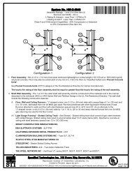
The hourly fire rating of the joint system is equal to the hourly fire rating of the wall.<br />
3. Joint System - Max separation between bottom of floor or roof deck and top of gypsum board (at time of installation<br />
of joint system) is 1 in. (25 mm). The joint system is designed to accommodate a max 18.75 percent compression or<br />
extension from its installed width. The joint system shall consist of forming and fill materials, with or without a deflection<br />
channel (Item 2A), as follows:<br />
A. Deflection Channel - (Optional, Not Shown) - Max 2 in. (51 mm) deep min 24 gauge galv steel channel sized to<br />
accommodate ceiling runner (Item 2A). Deflection channel installed perpendicular to direction of fluted steel deck prior to the<br />
application of spray-applied fire resistive material and secured to steel floor or roof deck valleys with steel masonry anchors<br />
fasteners or welds spaced max 24 in. (610 mm) OC. The ceiling runner is installed within the deflection channel to maintain a<br />
1/2 in. (13 mm) to 3/4 in. (19 mm) gap between the top of the ceiling runner and the top of the deflection channel. The ceiling<br />
runner nests inside the deflection channel without attachment.<br />
B. Forming Material* - Min 5-5/8 in. (143 mm) or 7 in. (178 mm) thickness of 4 pcf (64 kg/m3) mineral wool batt insulation for 1<br />
and 2 hr fire rated assemblies, respectively, cut to the shape of the fluted deck and installed into the flutes of the steel floor or<br />
roof deck between the top of the deflection channel and the steel floor or roof deck. The mineral wool batt insulation is to be<br />
compressed min 14.3 percent in thickness such that it is flush with the gypsum board surface on both sides of the wall.<br />
Additional sections of mineral wool batt insulation are compressed 50 percent in thickness and installed cut edge first to<br />
completely fill the gap above the top of the gypsum board. The forming material shall be installed flush with both surfaces of<br />
wall.<br />
IIG MINWOOL L L C - MinWool-1200 Safing<br />
ROCK WOOL MANUFACTURING CO - Delta Board<br />
ROCKWOOL MALAYSIA SDN BHD - SAFE<br />
ROXUL INC - SAFE<br />
THERMAFIBER INC - Type SAF<br />
C. Fill, Void or Cavity Material*-Sealant - Min 1/8 in. (3.2 mm) wet thickness or 1/16 in. (1.6 mm) dry thickness of fill<br />
material spray applied on each side of the wall in the flutes of the steel floor or roof deck and between the top of the wall<br />
and the bottom of the steel floor or roof deck and overlap a min 1/2 in. (13 mm) onto gypsum board and a min 2 in. (51<br />
mm) onto the spray applied material on both sides of wall.<br />
SPECIFIED TECHNOLOGIES INC - SpecSeal AS200 Elastomeric Spray<br />
*Bearing the UL Classification Mark<br />
Reproduced courtesy of Underwriters Laboratories, <strong>Inc</strong>.<br />
Created or Revised: January 11, 2011<br />
(800)992-1180 (908)526-8000 FAX (908)231-8415 E-Mail:techserv@stifirestop.com Website:www.stifirestop.com<br />
R<br />
<strong>HW</strong>-D-<strong>0088</strong><br />
PAGE 3 OF 3