W-L-3248 - STI - Specified Technologies Inc
W-L-3248 - STI - Specified Technologies Inc
W-L-3248 - STI - Specified Technologies Inc

Create successful ePaper yourself
Turn your PDF publications into a flip-book with our unique Google optimized e-Paper software.
System No. W-L-<strong>3248</strong><br />
Ì78WL0Ç@PÈAQÇ',,LÎ<br />
ANSI/UL1479 (ASTM E814)<br />
F Ratings - 1 and 2 Hr (See Item 1)<br />
T Ratings - 3/4 and 1 Hr (See Item 2)<br />
CAN/ULC S115<br />
F Ratings - 1 and 2 Hr (See Item 1)<br />
FT Ratings - 3/4 and 1 Hr (See Item 2)<br />
FH Ratings - 1 and 2 Hr (See Item 1)<br />
FTH Ratings - 3/4 and 1 Hr (See Item 2)<br />
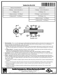
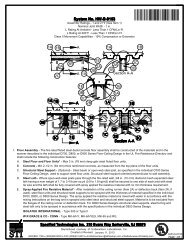
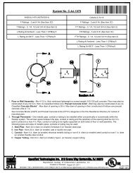
1. Wall Assembly - The 1 or 2 hr fire rated gypsum board/stud wall assembly shall be constructed of the materials<br />
and in the manner described within the individual U300, U400, V400 or W400 Series Wall and Partition Designs<br />
in the UL Fire Resistance Directory and shall incorporate the following construction features:<br />
A. Studs - Wall framing shall consist of either wood studs or steel channel studs. Wood studs to consist of nom<br />
2 by 4 in. (51 by 102 mm) lumber spaced max 16 in. (406 mm) OC. Steel studs to be min 3-1/2 in. (89 mm)<br />
wide and spaced max 24 in. (610 mm) OC.<br />
B. Gypsum Board* - Thickness, type, number of layers and fasteners as specified in the individual Wall and<br />
Partition Design. Opening in gypsum board to accommodate firestop device may be square or rectangular.<br />
Min distance between periphery of through opening and edge of two-piece steel plate (Item 3) is 1 in. (25<br />
mm).<br />
The hourly F and FH Ratings of the firestop system are dependent upon the hourly rating of the wall<br />
in which it is installed.<br />
2. Cables - Cables may represent a 0 to 100 percent visual fill within the loading area for each firestop device<br />
module. Cables to be rigidly supported on both sides of the wall assembly. Any combination of the following<br />
types of cables may be used:<br />
A. Max 100 pair No. 24 AWG (or smaller) copper conductor telecommunication cable with polyvinyl chloride<br />
(PVC) jacketing and insulation.<br />
B. Max 350 kcmil single copper conductor power cable with XLPE jacket and insulation<br />
C. Max 7/C No. 12 AWG copper conductor control cable with PVC or XLPE jacket and insulation.<br />
D. Max 3/C No. 10 AWG metal clad or armored cable with steel or aluminum jacket.<br />
E. Max 3/C No. 8 AWG NM cable (Romex) with PVC insulation and jacket.<br />
Reproduced courtesy of Underwriters Laboratories, <strong>Inc</strong>.<br />
Created or Revised: July 12, 2012<br />
(800)992-1180 (908)526-8000 FAX (908)231-8415 E-Mail:techserv@stifirestop.com Website:www.stifirestop.com<br />
R<br />
W-L-<strong>3248</strong><br />
PAGE 1OF<br />
2
F. Max four pair No. 22 AWG (or smaller) copper conductor data cable with polyvinyl chloride (PVC) jacketing<br />
and insulation.<br />
G. Max RG/U coaxial cable with fluorinated ethylene insulation and jacketing.<br />
H. Fiber optic cable with polyvinyl chloride (PVC) or polyethylene (PE) jacket and insulation having a max diam<br />
of 5/8 in. (16 mm).<br />
I. Max four pair No. 24 AWG (or smaller) copper conductor data cable with plenum rated jacket and insulation.<br />
When the hourly rating of the wall assembly is 1 hr, the T, FT and FTH Ratings are 3/4 hr. When the<br />
hourly rating of the wall assembly is 2 hr, the T, FT and FTH Ratings are 3/4 hr when Item 2A, 2B, 2C,<br />
2D or 2E is used. Otherwise, the T, FT and FTH Ratings are 1 hr.<br />
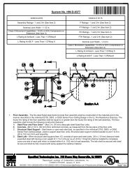
3. Firestop Device* - Firestop device consists of a 3 by 3 by 10-1/2 in. (76 by 76 by 267 mm) long galv steel tube<br />
with an intumescent material lining. Firestop device to be installed in accordance with the accompanying<br />
installation instructions. Prior to installation within wall, attachment screws and lid removed from device to<br />
capture grouped cables. After installation of cables, lid replaced and reattached with same screws. Device slid<br />
along cables into wall such that lid is on top and ends project an equal distance from the approximate centerline<br />
of the wall assembly. Two-piece steel plate supplied by manufacturer installed on each side of wall according to<br />
manufacturer\'s instructions. Steel plate incorporates an insulation gasket material installed prior to installation<br />
of steel plates. Steel plates fastened to gypsum board layers with nom 1/8 in. (3.2 mm) diam steel hollow-wall<br />
anchors in conjunction with nom 1 in. (25 mm) steel fender washers. Steel plates may be aligned or offset on<br />
each side of the wall to cover opening with min 1 in. (25 mm) overlap beyond periphery of through opening.<br />
SPECIFIED TECHNOLOGIES INC - EZ PATH Series 33 Fire Rated Pathway<br />
3A. Firestop Device* - Extension Module - (Optional, Not Shown) - Module attached to ends of 3 by 3 by 10-1/2<br />
in. (76 by 76 by 267 mm) long firestop device (Item 3) to increase its length to facilitate installation in thicker<br />
walls. Each module consists of a 3 by 3 by 6 in. (76 by 76 by 152 mm) long galv steel tube with an intumescent<br />
material lining. Extension module to be installed in accordance with the accompanying installation instructions.<br />
When module is used, firestop device (Item 3) and extension module(s) secured in place by means of steel wall<br />
plates installed with gasketing material supplied with product. Steel wall plates installed on both sides of wall<br />
and secured to each device or extension module(s) by means of steel set screws provided with wall plates.<br />
Firestop device and extension module(s) assembly to be installed with ends projecting an equal distance<br />
beyond each surface of the wall assembly.<br />
SPECIFIED TECHNOLOGIES INC - EZ PATH Extension<br />
*Bearing the UL Classification Mark<br />
Reproduced courtesy of Underwriters Laboratories, <strong>Inc</strong>.<br />
Created or Revised: July 12, 2012<br />
(800)992-1180 (908)526-8000 FAX (908)231-8415 E-Mail:techserv@stifirestop.com Website:www.stifirestop.com<br />
R<br />
W-L-<strong>3248</strong><br />
PAGE 2 OF 2