FC-2158 - STI - Specified Technologies Inc
FC-2158 - STI - Specified Technologies Inc
FC-2158 - STI - Specified Technologies Inc

You also want an ePaper? Increase the reach of your titles
YUMPU automatically turns print PDFs into web optimized ePapers that Google loves.
Ì80<strong>FC</strong>0Ç5ZÈAKÇ+;,FÎ<br />
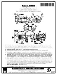
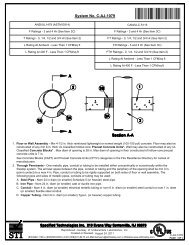
F Ratings - 1 and 2 Hr (See Item 1)<br />
T Ratings - 1 and 2 Hr (See Item 1)<br />
L Rating At Ambient - Less Than 1 CFM/sq ft<br />
L Rating At 400 F - Less Than 1 CFM/sq ft<br />
4 5D 1A<br />
3 5D<br />
1B<br />
1D<br />
5A<br />
5B<br />
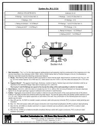
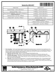
1. Floor-Ceiling Assembly - The 1 hr fire-rated solid or trussed lumber joist floor-ceiling assembly shall be constructed of the<br />
materials and in the manner specified in the individual L500 Series Floor-Ceiling Designs in the UL Fire Resistance Directory.<br />
The 2 hr fire-rated wood joist floor-ceiling assembly shall be constructed of the materials and in the manner specified in Design<br />
Nos. L505, L511 or L536 in the UL Fire Resistance Directory. The F and T Ratings of the firestop system are equal to the<br />
rating of the floor-ceiling assembly. The general construction features of the floor-ceiling assembly are summarized below:<br />
A. Flooring System - Lumber or plywood subfloor with finish floor of lumber, plywood or Floor Topping Mixture* as specified in<br />
the individual Floor-Ceiling Design. Diam of opening hole-sawed in flooring shall be max 1 in. (25 mm) larger than diam of<br />
through penetrant (Item 3) or branch piping (Item 4). As an option, the opening for the branch piping (Item 4) may be<br />
rectangular, 8 in. by 12 in. (204 by 305 mm) max, for 1 hr rated assemblies only. Cutout to be patched on underside of<br />
subfloor using one layer of min 3/4 in. (19 mm) thick plywood or min 5/8 in. (16 mm) thick gypsum wallboard (Item 1C) sized<br />
to lap min 2 in. (51 mm) beyond each edge of rectangular cutout. Diam of opening hole sawed through patch to accommodate<br />
branch piping (Item 4) to be max 1 in. (25 mm) larger than diam of branch piping. Patch split into two pieces at opening<br />
hole-sawed for branch piping. Two pieces positioned around branch piping, with cut edges tightly-butted, and screw attached<br />
to the underside of subfloor using 1-1/4 in. (32 mm) long Type S steel screws spaced max 6 in. (152 mm) OC.<br />
B. Wood Joists* - For 1 hr fire-rated floor-ceiling assemblies nom 10 in. (254 mm) deep (or deeper) lumber, steel or<br />
combination lumber and steel joists, trusses or Structural Wood Members* with bridging as required and with ends<br />
firestopped. For 2 hr fire-rated floor-ceiling assembly, nom 2 by 10 in. (51 by 254 mm) lumber joists spaced 16 in. (406 mm)<br />
OC with nom 1 by 3 in. (25 by 76 mm) lumber bridging with ends firestopped.<br />
C. Furring Channels - Not Shown)-Resilient galv steel furring installed perpendicular to wood joists between first and second<br />
layers of gypsum board (Item 1D) in 2 hr fire-rated assembly.<br />
D. Gypsum Board* - Nom 4 ft (1.2 m) wide by 5/8 in. (16 mm) thick as specified in the individual Floor-Ceiling Design. First<br />
layer of gypsum board nailed to wood joists. Second layer of gypsum board (2 hr fire-rated assembly) screw-attached to<br />
furring channels. Diam of opening shall be max 1 in. (25 mm) larger than nom diam of through penetrant (Item 3).<br />
Reproduced courtesy of Underwriters Laboratories, <strong>Inc</strong>.<br />
Created or Revised: November 27, 2012<br />
(800)992-1180 (908)526-8000 FAX (908)231-8415 E-Mail:techserv@stifirestop.com Website:www.stifirestop.com<br />
R<br />
F-C-<strong>2158</strong><br />
PAGE 1 OF 3
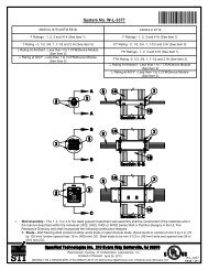
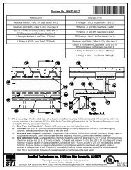
2. Chase Wall - (Optional, not shown)-The through-penetrant (Item 3) may be routed through a 1 or 2 hr fire-rated single, double or<br />
staggered wood stud/gypsum board chase wall constructed of the materials and in the manner specified in the individual U300<br />
Series Wall and Partition Designs in the UL Fire Resistance Directory and which includes the following construction features:<br />
A. Studs - Nom 2 by 6 in. (51 by 152 mm) or double nom 2 by 4 in. (51 by 102 mm) lumber studs.<br />
B. Sole Plate - Nom 2 by 6 in. (51 by 152 mm) or parallel 2 by 4 in. (51 by 102 mm) lumber plates, tightly butted. Diam of<br />
opening hole-sawed in sole plate to be max 1 in. (25 mm) larger than diam of through penetrant (Item 3).<br />
C. Top Plate - The double top plate shall consist of two nom 2 by 6 in. (51 by 152 mm) or two sets of parallel 2 by 4 in. (51 by<br />
102 mm) lumber plates, tightly butted. Diam of opening shall be max 1 in. (25 mm) larger than diam of through penetrant (Item<br />
3).<br />
D. Gypsum Board* - Thickness, type, number of layers and fasteners shall be as specified in the individual Wall or Partition<br />
Design.<br />
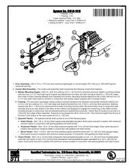
3. Through-Penetrant - One nonmetallic pipe to be centered within the firestop system. Pipe to be rigidly supported on both sides<br />
of floor-ceiling assembly. The annular space between pipe and periphery of opening shall be min 0 in. (point contact) to max 1/2<br />
in. (0 to 13 mm). Pipe may be installed with continuous point contact where it passes through gypsum board ceiling. The<br />
following types and sizes of nonmetallic pipes may be used:<br />
A. Polyvinyl Chloride (PVC) Pipe - Nom 4 in. (102 mm) diam (or smaller) Schedule 40 cellular or solid core PVC pipe for use in<br />
closed (process or supply) or vented (drain, waste or vent) piping system.<br />
B. Chlorinated Polyvinyl Chloride (CPVC) Pipe - Nom 4 in. (102 mm) diam (or smaller) SDR17 CPVC pipe for use in closed<br />
(process or supply) or vented (drain, waste or vent) piping system.<br />
C. Acrylonitrile Butadiene Styrene (ABS) Pipe - Nom 4 in. (102 mm) diam (or smaller) Schedule 40 cellular or solid core ABS<br />
pipe for use in closed (process or supply) or vented (drain, waste or vent) piping system.<br />
4. Branch Piping - (Optional)-One nonmetallic pipe with or without nom 4 in. (102 mm) diam (or smaller) toilet flange (not shown)<br />
connected to through penetrant (Item 3) within concealed space above ceiling and centered within opening in subfloor. The<br />
annular space between pipe and periphery of opening shall be min 0 in. (point contact) to max 1/2 in. (0 to 13 mm). Branch piping<br />
may terminate in a max 4 in. (102 mm) diam toilet flange that corresponds to the type of branch piping. The following types and<br />
sizes of nonmetallic pipes may be used:<br />
A. Polyvinyl Chloride (PVC) Pipe - Nom 4 in. (102 mm) diam (or smaller) Schedule 40 cellular or solid core PVC pipe for use in<br />
closed (process or supply) or vented (drain, waste or vent) piping system.<br />
B. Chlorinated Polyvinyl Chloride (CPVC) Pipe - Nom 4 in. (102 mm) diam (or smaller) SDR17 CPVC pipe for use in closed<br />
(process or supply) or vented (drain, waste or vent) piping system.<br />
C. Acrylonitrile Butadiene Styrene (ABS) Pipe - Nom 4 in. (102 mm) diam (or smaller) Schedule 40 cellular or solid core ABS<br />
pipe for use in closed (process or supply) or vented (drain, waste or vent) piping system.<br />
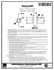
5. Firestop System - The details of the firestop system shall be as follows:<br />
A. Fill, Void or Cavity Material* - Wrap Strip - Nom 1/8 or 1/4 in. (3.2 or 6 mm) thick intumescent material faced on both sides<br />
with a plastic film, supplied in 1-1/2 in. or 2 in. (38 or 51 mm) wide strips. Nom 1-1/2 in. or 2 in. (38 or 51 mm) wide strips<br />
tightly wrapped around through penetrant (Item 3) with the edges butted against the underside of the gypsum board ceiling<br />
(Item 1D) or top plate of chase wall (Item 2C) around the entire perimeter of the hole-sawed opening. For nom 1/2 in. to 2 in.<br />
(13 to 51 mm) diam pipes, a min of one layer of wrap strip is required. For nom 2-1/2 in. to nom 4 in. (64 to 102 mm) diam<br />
pipes, a min of two layers of wrap strip is required. Each layer of wrap strip to be installed with butted seams, butted seams in<br />
successive layers to be staggered or aligned. Wrap strip layer(s) secured together with masking tape.<br />
SPECIFIED TECHNOLOGIES INC - SpecSeal RED Wrap Strip, SpecSeal RED2, SpecSeal BLU Wrap Strip or SpecSeal<br />
BLU2 Wrap Strip<br />
Reproduced courtesy of Underwriters Laboratories, <strong>Inc</strong>.<br />
Created or Revised: November 27, 2012<br />
(800)992-1180 (908)526-8000 FAX (908)231-8415 E-Mail:techserv@stifirestop.com Website:www.stifirestop.com<br />
R<br />
F-C-<strong>2158</strong><br />
PAGE 2OF<br />
3
B. Steel Collar - Collar fabricated from coils of precut 0.016 in. (0.4 mm) thick (30 MSG) galv sheet steel available from wrap<br />
strip manufacturer. Collar shall be nom 1-1/2 in. or 2 in. (38 or 51 mm) deep dependent upon wrap strip width with 1 in. (25<br />
mm) wide by 2 in. (51 mm) long anchor tabs for attachment to underside of ceiling or top plate. Retainer tabs, 3/4 in. (19 mm)<br />
wide tapering down to 1/4 in. (6 mm) wide and located opposite the anchor tabs, folded 90 degrees toward through penetrant<br />
surface to maintain the annular space and to retain the wrap strips. Collar wrapped around wrap strips and through-penetrant<br />
with a 1 in. (25 mm) wide overlap along its perimeter joint and secured with a min 1/2 in. (13 mm) wide by 0.028 in. (0.7 mm)<br />
thick stainless steel hose clamp at the mid-height of the steel collar. As an alternate to the steel hose clamp, the steel collar<br />
may be secured together by means of three No. 8 steel sheet metal screws. The length of the steel screws is dependent upon<br />
the number of layers of wrap strip used within the steel collar. For steel collars incorporating a single layer of wrap strip, the<br />
length of the steel screws shall be 1/4 in. (6 mm) long. For steel collars incorporating two or more layers of wrap strip, the<br />
length of the steel screws shall be 3/8 in. (10 mm) long. Collar secured to the bottom of ceiling with min 3/16 in. (4.8 mm)<br />
diam by 2 in. (51 mm) long toggle bolts in conjunction with min 1/4 in. by 1-1/4 in. (6 by 32 mm) steel fender washers. Collar<br />
secured to bottom of chase wall top plate with min 3/4 in. (19 mm) long steel wood screws in conjunction with min 1/4 in. by 1<br />
in. (6 by 25 mm) steel fender washers, respectively. The number of screws is dependent upon the nom diam of the through<br />
penetrant. Two screws, symmetrically located, are required for nom 1/2 in. through 2 in. (13 to 51 mm) diam<br />
through-penetrants. Three screws, symmetrically located, are required for nom 2-1/2 in. and 3 in. (64 to 76 mm) diam<br />
through-penetrants. Four screws, symmetrically located, are required for nom 3-1/2 in. and 4 in. (89 to 102 mm) diam<br />
through-penetrants. Steel collar is not required to be installed around branch piping at the underside of the flooring.<br />
C. Firestop Device* - (Not Shown)-As an alternate to Items 5A and 5B for through-penetrant (Item 3), a firestop device<br />
consisting of a steel collar lined with intumescent material and sized to fit the specific diam of the nonmetallic pipe may be<br />
used. Firestop device to be installed on underside of ceiling or top plate in accordance with the accompanying installation<br />
instructions.<br />
SPECIFIED TECHNOLOGIES INC - SpecSeal Firestop Collar, SpecSeal LCC Collar or SpecSeal SSC Collar<br />
D. Fill, Void or Cavity Material* -Sealant - Min 3/4 in. (19 mm) thickness of fill material applied within annular space around<br />
perimeter of through penetrant (Item 3) and branch piping (Item 4), flush with top surface of floor or top of chase wall sole<br />
plate. Min 1/2 in. (13 mm) diam bead applied at point contact locations at pipe/floor interface and the pipe/plate interface.<br />
SPECIFIED TECHNOLOGIES INC - SpecSeal Series Sealant or SpecSeal LCI Sealant<br />
*Bearing the UL Classification Mark<br />
Reproduced courtesy of Underwriters Laboratories, <strong>Inc</strong>.<br />
Created or Revised: November 27, 2012<br />
(800)992-1180 (908)526-8000 FAX (908)231-8415 E-Mail:techserv@stifirestop.com Website:www.stifirestop.com<br />
R<br />
F-C-<strong>2158</strong><br />
PAGE 3 OF 3