C-AJ-1198 - STI - Specified Technologies Inc
C-AJ-1198 - STI - Specified Technologies Inc
C-AJ-1198 - STI - Specified Technologies Inc

Create successful ePaper yourself
Turn your PDF publications into a flip-book with our unique Google optimized e-Paper software.
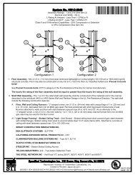
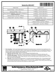
F Ratings - 2 and 3 Hr (See Items 2, 3D, 3E and 4B)<br />
T Rating - 0 Hr<br />
L Rating At Ambient - Less Than 1 CFM/Sq Ft<br />
L Rating At 400F - Less Than 1 CFM/Sq Ft<br />
W Rating - Class 1<br />
Ì72C<strong>AJ</strong>Ç+ÆÈADÇ+:(OÎ<br />
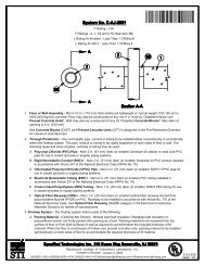
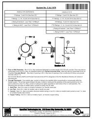
1. Floor or Wall Assembly - Min 4-1/2 in. (114 mm) thick reinforced lightweight or normal weight (100-150 pcf or 1600-2400<br />
kg/m3) concrete floor or min 5 in. (127 mm) thick reinforced lightweight or normal weight concrete wall. Wall may also be<br />
constructed of any UL Classified Concrete Blocks*. Floor may also be constructed of any UL Classified hollow core Precast<br />
Concrete Units*. Max diam of opening is 7 in. (178 mm) when floor is constructed of hollow-core precast concrete units.<br />
Otherwise, max diam of opening is 26 in. (660 mm).<br />
See Concrete Blocks (CAZT) and Precast Concrete Units (CFTV) categories in the Fire Resistance Directory for names of<br />
manufacturers.<br />
2. Steel Sleeve - (Optional, Not Shown) - Max 14 in. (356 mm) diam Schedule 10 (or heavier) steel pipe sleeve or max 14 in.<br />
(356 mm) diam No. 26 ga (or heavier) sheet steel with square flange spot-welded to the sleeve near its midheight and sized to<br />
be a min of 2 in. (51 mm) larger than the OD of the through penetrant. Sleeve cast or grouted into floor or wall flush with both<br />
surfaces of floor or wall. When steel sleeve is used, F Rating of firestop system is 2 Hr.<br />
3. Through Penetrant - One metallic pipe, conduit or tubing to be installed either concentrically or eccentrically within the firestop<br />
system. The annular space between pipes, conduits or tubing and periphery of opening shall be min 0 in. ( 0 mm, point<br />
contact) to max 2-1/4 in. (57 mm). Pipe, conduit or tubing to be rigidly supported on both sides of floor or wall assembly. The<br />
following types and sizes of metallic pipes, conduits or tubing may be used:<br />
A. Steel Pipe - Nom 24 in. (610 mm) diam (or smaller) Schedule 10 (or heavier) steel pipe. When steel sleeve is used, the<br />
max pipe diam is 12 in. (305 mm).<br />
B. Iron Pipe - Nom 24 in. (610 mm) diam (or smaller) cast or ductile iron pipe. When steel sleeve is used, the max pipe<br />
diam is 12 in. (305 mm).<br />
C. Conduit - Nom 4 in. (102 mm) diam (or smaller) steel electrical metallic tubing, nom 6 in. diam (or smaller) rigid steel<br />
conduit or nom 1 in. diam (or smaller) flexible steel conduit.<br />
D. Copper Tubing - Nom 6 in. (152 mm) diam (or smaller) Type L (or heavier) copper tubing. When max 6 in. (152 mm)<br />
diam copper tubing is used, F Rating is 2 hr. When max 4 in. (102 mm) diam copper tubing is used, F Rating is 3 hr.<br />
When steel sleeve is used, the max copper tubing diam is 4 in. (102 mm).<br />
E. Copper Pipe - Nom 6 in. (152 mm) diam (or smaller) Regular (or heavier) copper pipe. When max 6 in. (152 mm) diam<br />
copper pipe is used, F Rating is 2 hr. When max 4 in. (102 mm) diam copper pipe is used, F Rating is 3 hr. When<br />
steel sleeve is used, the max copper pipe diam is 4 in. (102 mm).<br />
Reproduced courtesy of Underwriters Laboratories, <strong>Inc</strong>.<br />
Created or Revised: November 26, 2008<br />
(800)992-1180 (908)526-8000 FAX (908)231-8415 E-Mail:techserv@stifirestop.com Website:www.stifirestop.com<br />
R<br />
C-<strong>AJ</strong>-<strong>1198</strong><br />
PAGE 1 OF 2
4. Firestop System - The firestop system shall consist of the following:<br />
A. Packing Material - Min 4 in. (102 mm) thickness of min 4 pcf (64 kg/m3) mineral wool batt insulation firmly packed into<br />
opening as a permanent form. Packing material to be recessed from top surface of floor or from both surfaces of wall to<br />
accommodate the required thickness of fill material. When floor is constructed of hollow-core precast concrete units<br />
the packing material is to be flush with the bottom surface of the floor and extend through the thickness of the<br />
floor except for the recess required at the top surface of the floor to accommodate the fill material.<br />
B. Fill, Void or Cavity Material* - Sealant - Fill material applied within the annulus, flush with top surface of floor or with both<br />
surfaces of wall. At the point contact location between penetrating item and concrete, a min 3/8 in. (10 mm) diam bead of fill<br />
material shall be applied at the concrete/penetrating item interface on the top surface of floor and on both surfaces of wall.<br />
When steel sleeve is used in concrete floor, a thin film of fill material shall be applied to cover edge of sleeve and to lap a<br />
min of 1/2 in. onto concrete. A min 1/4 in. (6 mm) thickness of sealant is required in the annulus for the 2 hr F Rating.<br />
A min 1/2 in. (13 mm) thickness of sealant is required in the annulus for the 3 hr F Rating.<br />
SPECIFIED TECHNOLOGIES INC - Pensil 300 Sealant or SpecSeal Series SIL300 Sealant for floors or walls and Pensil<br />
300 S/L Sealant or SpecSeal Series SIL300SL Sealant for floors only.<br />
*Bearing the UL Classification Mark<br />
Reproduced courtesy of Underwriters Laboratories, <strong>Inc</strong>.<br />
Created or Revised: November 26, 2008<br />
(800)992-1180 (908)526-8000 FAX (908)231-8415 E-Mail:techserv@stifirestop.com Website:www.stifirestop.com<br />
R<br />
C-<strong>AJ</strong>-<strong>1198</strong><br />
PAGE 2 OF 2