HW-D-0371 - STI - Specified Technologies Inc
HW-D-0371 - STI - Specified Technologies Inc
HW-D-0371 - STI - Specified Technologies Inc

You also want an ePaper? Increase the reach of your titles
YUMPU automatically turns print PDFs into web optimized ePapers that Google loves.
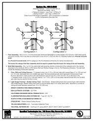
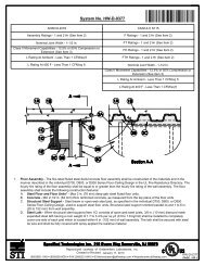
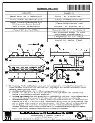
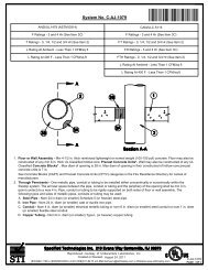
Assembly Ratings - 1 and 2 Hr (See Item 2)<br />
Nominal Joint Width - 3/4 in.<br />
L Rating At Ambient - Less Than 1 CFM/Lin Ft<br />
L Rating At 400°F - Less Than 1 CFM/Lin Ft<br />
Class II and III Movement Capabilities - 100% Compression or Extension<br />
Ì79<strong>HW</strong>DÇ#gÈAOÇ&
A2. Light Gauge Framing* - Vertical Deflection Ceiling Runner - As an alternate to the ceiling runner in Items 2A and 2A1.,<br />
vertical deflection ceiling runner to consist of galv steel channel with slotted vertical deflection clips mechanically fastened within<br />
runner. Slotted clips, provided with step bushings, for permanent fastening of steel studs. Vertical deflection ceiling runner<br />
secured to underside of concrete floor with steel fasteners spaced max 24 in. (610 mm) OC. When slotted ceiling runner is<br />
used, deflection channel (Item 3A) shall not be used.<br />
THE STEEL NETWORK INC - VertiTrack VTD362, VTD400, VTD600 and VTD800<br />
A3. Light Gauge Framing* - Clipped Ceiling Runner - As an alternate to the ceiling runner in Items 2A, 2A1 and 2A2, clipped<br />
runner to consist of galv steel channel with clips preformed in track flanges which positively engage the inside flange of the steel<br />
studs (Item 2B). Track sized to accommodate steel studs (Item 2B). Track flanges to be min 2-3/4 in. (70 mm). Clipped ceiling<br />
runner secured to underside of concrete floor with steel fasteners spaced max 24 in. (610 mm) OC. When clipped ceiling runner<br />
is used, deflection channel (Item 3A) shall not be used.<br />
TOTAL STEEL SOLUTIONS L L C - Snap Trak<br />
B. Studs - Steel studs to be min 3-1/2 in. (89 mm) wide. Studs cut min 3/4 in. (19 mm) less in length than assembly height with<br />
bottom nesting in and secured to floor runner. When deflection channel (Item 3A) is used, steel studs attached to ceiling runner<br />
with sheet metal screws located 1 in. (25 mm) below the bottom of the deflection channel. When deflection channel is not used,<br />
studs to nest in ceiling runner without attachment. When slotted ceiling runner (Item 2A1) is used, steel studs secured to slotted<br />
ceiling runner with No. 8 by 1/2 in. (13 mm) long wafer head steel screws at midheight of slot on each side of wall. When vertical<br />
deflection ceiling runner (Item 2A2) is used, steel studs secured to slotted vertical deflection clips, through the bushings, with<br />
steel screws at midheight of each slot. Stud spacing not to exceed 24 in. (610 mm) OC.<br />
C. Gypsum Board* - Gypsum board sheets installed to a min total thickness of 5/8 in. (16 mm) or 1-1/4 in. (32 mm) on each side<br />
of wall for 1 and 2 hr fire rated assemblies, respectively. Wall to be constructed in the individual U400 or V400 Series Design in<br />
the UL Fire Resistance Directory, except that a max 3/4 in. gap shall be maintained between the top of the gypsum board and<br />
the underside of the concrete floor. The screws attaching the gypsum board to the studs along the top of the wall shall be<br />
located 1 in. (25 mm) below the bottom of the ceiling runner. No gypsum board attachment screws shall be driven into the<br />
ceiling runner or into the optional deflection channel.<br />
The hourly fire rating of the joint system is equal to the hourly fire rating of the wall.<br />
3. Joint System - Max separation between bottom of floor and top of gypsum board (at time of installation of joint system) is<br />
3/4 in. (19 mm). The joint system is designed to accommodate a max 100 percent compression or extension from it's<br />
installed width. The joint system shall consist of forming and fill materials, with or without a deflection channel (Item 3A), as follows:<br />
A. Deflection Channel - (Optional, Not Shown)-Max 2 in. (51 mm) deep min 25 gauge galv steel channel sized to accommodate<br />
ceiling runner (Item 2A). Deflection channel secured to underside of concrete floor with steel fasteners spaced max 24 in. (610<br />
mm) OC. The ceiling runner is installed within the deflection channel to maintain a min 3/4 in. (19 mm) gap between the top of<br />
the ceiling runner and the top of the deflection channel. The ceiling runner nests inside the deflection channel without<br />
attachment.<br />
B. Forming Material* - Nom 3/16 in. (4.8 mm) thick by 4 in. (102 mm) high joint forming material profile installed on both sides of<br />
the wall assembly. Profile installed by first marking a line across the top of the wall 3 in. (76 mm) below the underside of the<br />
concrete floor. Joint profile material positioned with its top edge against the underside of the concrete floor, in line with the plane<br />
of the wall surface, with the bottom edge on the line scribed on the wall assembly. Bottom of the joint profile attached to the<br />
gypsum board with nom 1/2 in. (13 mm) long steel staples spaced not greater than 8 in. (203 mm) OC. Adjoining lengths of<br />
profile to overlap approx 3/4 in. (19 mm) at shiplapped ends.<br />
SPECIFIED TECHNOLOGIES INC - SpecSeal Speed Flex Joint Profile<br />
C. Fill, Void or Cavity Material* - Sealant - Min 1/8 in. (3.2 mm) wet thickness (min 1/16 in. or 1.6 mm dry thickness) of fill<br />
material spray applied to completely cover forming material on each side of the wall with a min 1/2 in. (13 mm) overlap onto the<br />
gypsum board and concrete floor on both sides of the wall.<br />
SPECIFIED TECHNOLOGIES INC - SpecSeal AS200 Elastomeric Spray<br />
*Bearing the UL Classification Mark<br />
Reproduced courtesy of Underwriters Laboratories, <strong>Inc</strong>.<br />
Created or Revised: June 28, 2011<br />
(800)992-1180 (908)526-8000 FAX (908)231-8415 E-Mail:techserv@stifirestop.com Website:www.stifirestop.com<br />
R<br />
<strong>HW</strong>-D-<strong>0371</strong><br />
PAGE 2OF<br />
2