ASSEMBLY & OPERATION MANUAL - Inspire Fitness
ASSEMBLY & OPERATION MANUAL - Inspire Fitness
ASSEMBLY & OPERATION MANUAL - Inspire Fitness

Create successful ePaper yourself
Turn your PDF publications into a flip-book with our unique Google optimized e-Paper software.
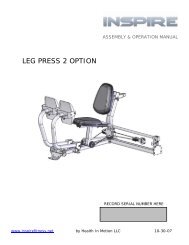
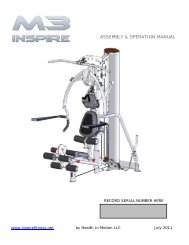
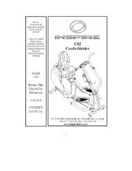
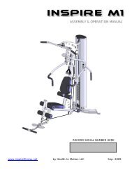
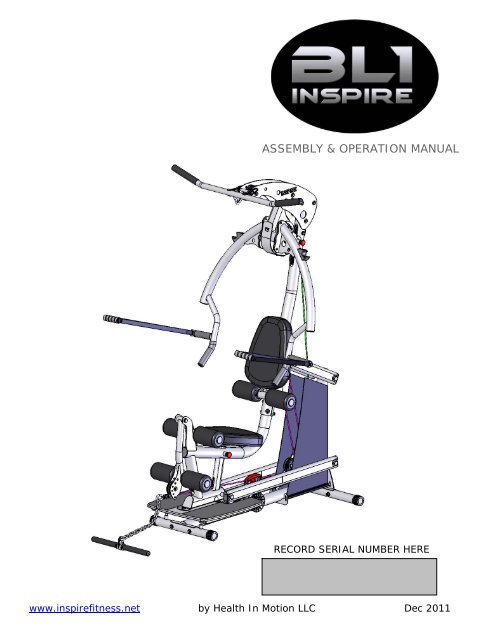
<strong>ASSEMBLY</strong> & <strong>OPERATION</strong> <strong>MANUAL</strong><br />
RECORD SERIAL NUMBER HERE<br />
www.inspirefitness.net by Health In Motion LLC Dec 2011
CONGRATULATIONS… You’ve just taken the first step to a healthier<br />
and stronger body. This home gym by <strong>Inspire</strong> offers the key to unlocking<br />
your body’s potential. Regular strength training on a home gym has been<br />
shown to deliver a host of benefits including: increased muscle tone,<br />
decreased body fat, improved energy levels, a reduction in stress, and<br />
improved cardiac output. Once again, congratulations, you are on your way<br />
to improving your self image, overall health and quality of life.<br />
BEFORE ASSEMBLING YOUR HOME GYM<br />
IMPORTANT: Read this entire manual before attempting to build or use<br />
this machine. This manual contains step by step instructions for proper<br />
assembly.<br />
Use the parts list included in this manual to verify that all parts are<br />
accounted for before assembly. If any parts are missing, contact the retailer<br />
of this home gym for replacement parts. Or, call <strong>Inspire</strong> at 877-738-1729<br />
Make sure that adequate room has been cleared before attempting to build<br />
your home gym. A rubber mat is recommended for use under your home<br />
gym to protect wood flooring or carpeting from damage during assembly<br />
and usage.<br />
This home gym is intended for indoor use only. In addition, garages and<br />
screened in porches are not recommended due to high humidity or dust.<br />
Certain parts including guide rods can form rust in a humid environment,<br />
resulting in impaired function.<br />
Service of your home gym should only be preformed by an authorized<br />
INSPIRE retailer. Service preformed by anyone else can result in loss of<br />
warranty. If you need help finding an authorized retailer, please contact us<br />
directly:<br />
<strong>Inspire</strong> <strong>Fitness</strong><br />
4945 East Hunter Avenue<br />
Anaheim, CA 92807<br />
Ph: 877-738-1729<br />
Fx: 714-738-1728<br />
www.inspirefitness.net
TABLE OF CONTENTS<br />
Section Description…………………………………………………….<br />
Page<br />
Important Safety Instructions………………………………………. 1<br />
Tools Required………………………………………………………………… 1<br />
Parts & Hardware List……………………………………………………. 2<br />
Assembly Instructions………………………………………………..…. 3-20<br />
Final Adjustments…………………………………………………………… 21<br />
Decal Reference……………………………………………………………… 22-23<br />
Accessories……………………………………………………………………… 24<br />
General Maintenance Information…….…………………………… 25<br />
Maintenance Schedule…….……………………………………………… 26<br />
Limited Warranty…………………………………………………………….. 27
IMPORTANT SAFETY INSTRUCTIONS<br />
Please read this entire manual and familiarize yourself with all decals and<br />
warnings before using this home gym.<br />
• WARNING! It is necessary to inspect this home gym regularly to<br />
maintain safety and proper function. Please use the maintenance schedule<br />
included towards the back of this manual. Immediately replace any and all<br />
defective or worn parts. Pay special attention to moving parts such as the<br />
cables and pulleys and connections to accessories. See General<br />
Maintenance section for complete details.<br />
• Use this home gym for its intended purpose as described in this Operation<br />
Manual or the exercise chart. Do not use attachments not recommended by<br />
the manufacturer.<br />
• Do not hang from press arm. The press arm is not designed to<br />
support human weight.<br />
• Make sure bystanders are at least 5 feet away from the home gym while<br />
it is in use.<br />
• Keep children off the home gym at all times.<br />
• Keep the home gym away from walls and clear of any obstructions and<br />
furniture.<br />
• Stop immediately if you experience shortness of breath, pain, or dizziness<br />
during your workout. <strong>Inspire</strong> strongly recommends consulting your doctor<br />
before starting an exercise program.<br />
TOOLS REQUIRED FOR <strong>ASSEMBLY</strong><br />
• Metric socket set (including 16mm, 17mm, 18mm, 19mm, and 24mm<br />
sockets)<br />
• 16mm, 17mm, 18mm, 19mm, and 24mm wrenches<br />
• Adjustable wrench<br />
• Tape Measure<br />
• Rubber Mallet<br />
PAGE 1
PARTS & HARDWARE LIST<br />
Part # Parts Description Q'ty Qty Rec'd Part# Hardware Description Q'ty Qty Rec'd<br />
1 Front Foot Assembly 1 77 Hex Bolt, M12*160 1<br />
2 Base Frame Assembly 1 79 Hex Bolt, M16*230 4<br />
3 Rear Foot Assembly 1 81 Hex Bolt, M10*70 6<br />
4 Shroud Mount Rod, Lower 2 82 Hex Bolt, M12*90 1<br />
5 Shroud Mount Bracket, Upper 1 83 Hex Bolt, M10*60 3<br />
6 Weight Selector Tube 1 85 Hex Bolt, M10*115 1<br />
7 Slider Assembly 1 86 Hex Bolt, M10*100 5<br />
8 Lower Arm 2 87 Hex Bolt, M10*40 2<br />
9 Upper Arm 2 88 Hex Bolt, M12*100 1<br />
10 Upper Main Frame Assembly 1 89 Hex Bolt, M12*80 1<br />
11 Lower Main Frame Assembly 1 90 Button Head Screw, M6*12 4<br />
13 Top Beam Plate 2 93 Button Head Screw, M6*75 1<br />
14 Press Arm Mount 1 94 Button Head Screw, M6*15 2<br />
16 Press Arm Mount Cover Plate 1 97 Button Head Screw, M10*90 4<br />
17 Lat Bar 1 98 Setscrew, M6*8 2<br />
18 Press Arm Assembly 1 99 Flathead Nut, φ17*23*M6 1<br />
20 Backpad Tilt Frame 1 100 Flat Head Nut, φ17*25.5*M6 2<br />
21 Roller Tube 3 102 Flat Head Screw, M10*15 2<br />
22 Pulley Bracket, Cable Tensioner 1 103 Philips Head Screw, M5*12 1<br />
23 Seat Stem 1 106 Cap Screw, M5*10 1<br />
24 Leg Extension Assembly 1 107 Flat washer, Φ10 24<br />
25 Revolving Straight Bar 1 108 Flat washer, Φ12 8<br />
26 Chain 1 111 Flat washer, Φ40*Φ16.5*2.5 8<br />
37 Pulley Assembly, Φ3 1/2" 11 112 Arc Washer, Φ10 16<br />
38L Shroud, Left 1 116 Lock Nut, M10 19<br />
38R Shroud, Right 1 117 Lock Nut, M12 4<br />
40 Step Bushing, Φ12 ID 8 118 Lock Nut, M16 4<br />
43 Large Plastic Washer 2 120 Allen Wrench, 3mm 1<br />
44 Foam Roller 6 121 Allen Wrench, 4mm 1<br />
45 Endcap, Roller Tube 6 122 4-Way Po Plug Wrench, 5mm 1<br />
47 Pop-Pin Shaft, 140 long 1 123 Allen Wrench, 6mm 1<br />
50 Lat Bar Holder 2<br />
51 Barrel Spacer, 1" Long 6<br />
52 Spacer Tube, 3" long 1<br />
53 Seat Pad 2<br />
65 Foot Plate Assembly 1<br />
68 Cable Assembly 1<br />
69 Cable Ball 2<br />
70 "U" Bracket, Cable End 2<br />
73 Spring Clip 3<br />
74 Adjustable Bumper 4<br />
PAGE 2
<strong>ASSEMBLY</strong> INSTRUCTIONS<br />
PAGE 3
STEP 1<br />
3<br />
Attach Front Foot Assembly (#1) to Base Frame Assembly (#2) using: Two (M10x70 Bolts)<br />
Attach Rear Foot Assembly (#3) to Base Frame Assembly (#2) using: Two (M10x70 Bolts)<br />
Wrench tighten all bolts now.<br />
Page 4 5/11
STEP 2<br />
Attach Slider Assembly (#7) to Weight Selector Tube(#6).<br />
Install M5x10 Screw (#106) into Weight Selector Stem (#6) and tighten.<br />
Insert two Step Bushings (#40) into the Weight Selector Tube (#6).<br />
Attach two 3 ½” Pulleys (#37) and two 1” long Barrel Spacers (#51)<br />
to Weight Selector Tube (#6) using:<br />
Two (M10x70 Bolts)<br />
Wrench Tighten Bolts Now.<br />
Page 5 12/11
STEP 3<br />
Attach Weight Selector Tube (#6) to Base Frame Assembly (#2) using:<br />
One (M12x90 Bolt)<br />
Wrench tighten bolt so there is a slight drag when moving Weight Selector<br />
Tube. Do not over tighten.<br />
Page 6 12/11
STEP 4<br />
Attach Lower Arms (#8) to Base Frame Assembly (#2) using:<br />
One (M16x230 Hex Bolt)<br />
Attach Upper Arms (#9) to Base Frame Assembly (#2) using:<br />
One (M16x230 Hex Bolt)<br />
Wrench Tighten bolts so there is a slight drag on the Arms when moved.<br />
Do not over tighten.<br />
Page 7 12/11
STEP 5<br />
11<br />
65<br />
Attach Lower Main Frame (#11) to Foot Plate (#65) using:<br />
Three (M10x60 Hex Bolt)<br />
Wrench Tighten Now.<br />
Page 8 5/11
STEP 6<br />
11<br />
8<br />
8<br />
Attach Lower Main Frame (#11) to Lower Arms (#8) using:<br />
One (M16x230 Hex Bolt)<br />
Wrench Tighten bolt so there is a slight drag when moving Lower Main Frame.<br />
Do not over tighten .<br />
Page 9 12/11
STEP 7<br />
9<br />
9<br />
11<br />
Attach Upper Main Frame (#10) to Lower Main Frame (#11) using:<br />
Four (M10*90 Allen Head Screws)<br />
Attach Upper Main Frame (#10) to Left & Right Upper Arms (#8 & #9) using:<br />
One (M16*230 Hex Bolt)<br />
Wrench tighten bolts now.<br />
Page 10 5/11
STEP 8<br />
10<br />
Attach Top Beam Plates (#13) and One 3 ½” Pulley (#37) to Upper Main Frame (#10) using:<br />
Four (M10*100 Hex Bolts)<br />
Two (1” Long barrel Spacers)<br />
Finger Tighten Only<br />
Attach Lat Bar Holders (#50) and One 3 ½” Pulley (#37) to Top Beam Plates (#13) Using:<br />
One (M10*115 Hex Bolt)<br />
One (M10*100 Hex Bolt)<br />
One (3” Spacer Tube)<br />
Two (1” Long barrel Spacers)<br />
Finger tighten bolts only. No not wrench tighten until after step 9.<br />
Page 11 12/11
117<br />
108<br />
STEP 9<br />
13<br />
108<br />
88<br />
14<br />
10<br />
47<br />
Attach Press Arm Mount (#14) to Top Beam Plates (#13) using: One (M12*100 Hex Bolt)<br />
Wrench Tighten bolt #88 so there is a slight drag when moving Press Arm Mount.<br />
Do not over tighten .<br />
Wrench tighten all bolts installed in Step 8.<br />
Attach Pop-Pin Shaft (#47) to Upper Main Frame (#10)<br />
Thread Completely and Wrench Tighten.<br />
Page 12 12/11
STEP 10<br />
18<br />
14<br />
Attach Press Arm (#18) to Press Arm Mount (#14) using: One (M12*160 Hex Bolt)<br />
Wrench Tighten bolt so there is a slight drag when moving Press Arm.<br />
Do not over tighten .<br />
Page 13 12/11
STEP 11<br />
14<br />
16<br />
103<br />
117 108<br />
108<br />
89<br />
11<br />
24<br />
Attach Leg Extension Assembly (#24) to Lower Main Frame (#11) using:<br />
One (M12*80 Hex Bolt)<br />
Wrench Tighten bolt so there is a slight drag when moving Leg Extension Assembly.<br />
Do not over tighten .<br />
Attach Press Arm Mount Cover Plate (#16) using: One (M5*12 Philips head Screw)<br />
Wrench Tighten Now.<br />
Page 14 12/11
STEP 12<br />
98<br />
10<br />
20<br />
99<br />
44 43<br />
93<br />
21<br />
43<br />
44<br />
45<br />
45<br />
Attach Back Pad Tilt Frame (#20) to Upper Main Frame (#10) using:<br />
One Roller Tube (#21) Two M6*8 Set Screws (#98)<br />
Two Foam Rollers (#44) One M6*75 Button Head Screw (#93)<br />
Two Large Plastic Washers (#43) One M6 Flat Head Nut (#99)<br />
Two End Caps (#45)<br />
Wrench Tighten bolt #93 so there is a slight drag when moving Back Pad tilt Frame.<br />
Do not over tighten .<br />
Note: Tighten the two set screws(#98) completely after Foam Rollers are installed.<br />
Page 15 12/11
STEP 13<br />
23<br />
53<br />
20<br />
53<br />
102<br />
107<br />
102<br />
87<br />
107<br />
87<br />
Attach Seat Pad (#53) to Seat Stem (#23) using: Two (M10*40 Hex Bolts)<br />
Wrench Tighten Now.<br />
Slide Seat Stem (#23) into Lower Main Frame (#11)<br />
Attach Back Pad (#53) to Backpad Tilt Frame (#20) using: Two (M10*15 Flat Head Screws)<br />
Wrench Tighten Now.<br />
Page 16 5/11
STEP 14<br />
45<br />
44<br />
45<br />
44<br />
21<br />
21<br />
24<br />
44<br />
45<br />
44<br />
45<br />
Attach 4 Foam Rollers (#44) to Leg Extension Assembly (#24) & Seat Stem (#23) using:<br />
Two Roller Tubes (#21)<br />
Four End Caps (#45)<br />
Page 17 12/11
STEP 15<br />
Pulley 1<br />
Pulley2<br />
94<br />
70<br />
69<br />
Pulley 3<br />
Pulley 4<br />
68<br />
Pulley 5<br />
Pulley 6<br />
73<br />
100<br />
Pulley 8<br />
Pulley 11<br />
Pulley 9<br />
Pulley 10<br />
Pulley 7<br />
Began at the top of the machine and run the cable sequentially from pulley #1 to pulley #11,<br />
as shown in the above drawing. Once complete, finish both cable ends with a plastic ball<br />
(#69), “U” bracket (#70), flat head nut (#100), button head bolt (#94), and a spring clip<br />
(#73). Look back over the cable routing to make sure that the cable is sitting securely in<br />
each pulley.<br />
Note: Wrench tighten “U” bracket hardware at both ends of the cable.<br />
Page 18 5/11
STEP 16<br />
38R<br />
5<br />
38L<br />
90<br />
90<br />
4<br />
Attach Left and Right Shrouds (#38L & #38R) by first slipping the top of each Shroud onto the<br />
horns of the upper shroud mount (#5), as shown above. Make sure seams are to the inside.<br />
Next, slide rods (#4) into the bottom of each shroud and attach to frame using:<br />
Four M6*12 Button Head Screws<br />
Note: Be sure to pull the shrouds down taut before tightening the four screws.<br />
Page 19 12/11
STEP 17<br />
73<br />
17<br />
73<br />
73<br />
26<br />
25<br />
Attach Lat Bar (#17) to Spring Clip (#73).<br />
Attach Chain (#26) to Spring Clip (#73) on the end of the Cable.<br />
Attach Revolving Curl Bar (#25) to Chain (#26) with Spring Clip (#73).<br />
Page 20 5/11
FINAL ADJUSTMENTS AFTER <strong>ASSEMBLY</strong><br />
Press Arm Stop<br />
Macro Cable Adjustment<br />
Nut #2<br />
Nut #1<br />
Weight<br />
Selector<br />
Handle<br />
Wooden Platform<br />
Weight Selector Rollers<br />
Front Rubber Bumper<br />
FINAL ADJUSTMENT: (if needed)<br />
Below the seat you will find the weight selector. Grab the weight selector handle and pull the spring<br />
loaded pin. Slide the weight selector from position one to fifteen. The rollers should move freely. If the<br />
weight selector rollers bind between positions 1-8, lift the wooden platform and adjust the two Front<br />
Rubber Bumpers up slightly. This will ease the pressure on the rollers and allow the weight selector<br />
mechanism to slide freely.<br />
If the Weight Selector Rollers bind between positions 8-15, thread the press arm stop completely into the<br />
frame. This will provide slack in the cable and ease the pressure on the Weight Selector Rollers. If the<br />
Weight Selector Rollers are still binding, loosen nut #1 in the Macro Cable Adjustment drawing above.<br />
Next, adjust nut #2 counter clockwise until the Weight Selector Rollers move freely. Re-tighten nut #1.<br />
NOTE:<br />
The cable on this gym will stretch over time. There are two places to eliminate cable slack. A large<br />
amount of cable slack can be removed by adjusting the pulley upward on the Macro Cable Adjustment.<br />
Start by loosening nut (#1) shown in the Macro Cable Adjustment drawing above. Next, using a wrench,<br />
turn nut (#2) clockwise until adequate cable slack has been removed. Finish by tightening nut #1 back<br />
up.<br />
To eliminate a small amount of cable slack, adjust the Press Arm Stop counter clockwise. Wrench tighten<br />
Jam Nut.<br />
Page 21 081711
DECAL REFERENCE<br />
877-738-1729<br />
PAGE 22
DECAL REFERENCE<br />
PAGE 23
ACCESSORIES<br />
• Exercise Wall Chart<br />
• Lat Bar<br />
• Revolving Curl Bar<br />
HOME GYM OPTIONS<br />
• D handles<br />
• Aluminum EZ Curl Bar<br />
• Ab Crunch Bar<br />
Training Tips<br />
CONSULT A PHYSICIAN BEFORE STARTING ANY EXERCISE PROGRAM<br />
1. Always warm up before you start weight training. This helps get<br />
your muscles warm and prevents injury. You can warm up with light<br />
cardio or by doing a light set of each exercise before going to heavier<br />
weights.<br />
2. Control the weight. Always work with a weight that you can handle<br />
through a full range of motion. Slow and steady movements are<br />
recommended.<br />
3. Breathe. Don’t hold your breath during your set. Holding your<br />
breath builds internal pressure which increases your change for broken<br />
blood vessels, as well as a hernia.<br />
4. Sit up straight. Pay attention to your posture and keep everything<br />
straight. Engage your abs in every movement to keep balanced and<br />
protect your spine.<br />
PAGE 24
GENERAL MAINTENANCE INFORMATION<br />
• Periodically inspect the cables for splitting, cracking or fraying. Also,<br />
watch for bulging or flat areas in the cable.<br />
• Immediately replace cables at the first signs of damage or wear. Never<br />
use equipment with damaged or worn cables.<br />
• Cables naturally stretch over time, so check cable slack periodically and<br />
adjust cable tension as needed.<br />
• Regularly inspect product for loose hardware.<br />
• Do not use or store equipment outdoors.<br />
• Inspect spring clips, swivels and handles for wear or damage. If wear or<br />
damage exists, replace immediately.<br />
• Locate and familiarize yourself with all warning decals on the home gym.<br />
• Replace damaged or worn upholstery immediately.<br />
PAGE 25
MAINTENANCE SCHEDULE<br />
ROUTINE<br />
Inspect: Links, Pull Pins,<br />
Spring Clips, Swivels,<br />
Weight Stack Pins<br />
Clean: Upholstery<br />
HOME<br />
MAINTENANCE<br />
WEEKLY<br />
WEEKLY<br />
ENTRY DATE<br />
Inspect: Cables and<br />
their Fittings<br />
Inspect: Tautness of all<br />
Shrouds<br />
Inspect: Accessory Bars<br />
and Handles<br />
WEEKLY<br />
WEEKLY<br />
3 MONTHS<br />
Inspect: All Decals<br />
3 MONTHS<br />
Inspect: All Nuts and<br />
Bolts. Tighten if Needed<br />
Inspect: Anti-Skid<br />
surfaces<br />
Clean and Lubricate:<br />
Guide Rods with a Teflon<br />
based lubricant<br />
Lubricate: Seat Sleeves<br />
and all Plastic Slides<br />
Clean and Wax: All<br />
Glossy Finishes<br />
Replace: Cables, Belts<br />
and Connecting Parts<br />
3 MONTHS<br />
3 MONTHS<br />
3 MONTHS<br />
3 MONTHS<br />
YEARLY<br />
2 YEARS<br />
PAGE 26
LIMITED WARRANTY<br />
In-Home Lifetime Warranty.<br />
This Warranty applies only in the United States to <strong>Inspire</strong> strength products manufactured or distributed by Health In<br />
Motion LLC. The warranty period to the original purchaser is lifetime of the original purchaser.<br />
Health In Motion warrants that the Product you have purchased for non-commercial, personal, family or household<br />
use from Health In Motion LLC or from an authorized Health In Motion reseller is free from defects in materials or<br />
workmanship under normal use during the warranty period. Your sales receipt, showing the date of purchase of the<br />
Product, is your proof of the date of purchase. This warranty extends only to you, the original purchaser. It is not<br />
transferable to anyone who subsequently purchases the Product from you. It excludes expendable parts such as paint<br />
and finish. This Warranty becomes VALID ONLY if the Product is assembled / installed according to the instructions /<br />
directions included with the Product.<br />
Replacement and repair of parts.<br />
During the warranty period Health In Motion will at no additional charge, repair or replace the Product if it becomes<br />
defective, malfunctions, or otherwise fails to conform with this Warranty under normal non-commercial, personal,<br />
family, or household use. In repairing the product Health In Motion may replace defective parts with, at the option of<br />
Health In Motion, serviceable used parts that are equivalent to new parts in performance, or new parts. All exchanged<br />
parts and Products replaced under this warranty will become the property of Health In Motion. Health In Motion<br />
reserves the right to change manufacturers and or specification of any part to cover any existing warranty.<br />
Service procedures.<br />
To obtain warranty parts, you must return the parts to Health In Motion or an authorized Health In Motion retailer in<br />
its original container (or equivalent). You must pre-pay any shipping charges, taxes, or any other charges associated<br />
with transportation of the Product. In addition, you are responsible for insuring any Product shipped or returned. You<br />
assume the risk of loss during shipment. You must present Health In Motion with proof-of-purchase documents<br />
(including the date of purchase, Model, and Serial Number). Any evidence of alteration, erasing or forgery of proof -<br />
of-purchase documents will be cause to void this Warranty.<br />
Conditions and Exceptions.<br />
This Warranty does not extend to any Product not purchased from Health In Motion LLC or from an authorized Health<br />
In Motion reseller. This Warranty does not extend to any Product that has been damaged or rendered defective; (a)<br />
as a result of accident, misuse, or abuse; (b) by the use of parts not manufactured or sold by Health In Motion; (c) by<br />
modification of the Product; (d) as a result of service by anyone other than Health In Motion, or an authorized Health<br />
In Motion warranty service provider; (e) product that has not been properly maintained (follow maintenance schedule<br />
found on product). Should any product submitted for Warranty service be found to be ineligible, an estimate of repair<br />
cost will be furnished and the repair will be made if requested by you upon Health In Motion receipt of payment or<br />
acceptable arrangement of payment.<br />
Disclaimer<br />
EXCEPT AS EXPRESSLY SET FORTH IN THIS WARRANTY HEALTH IN MOTION MAKES NO OTHER WARRANTIES;<br />
EXPRESSED OR IMPLIED INCLUDING ANY IMPLIED WARRANTIES OF MERCHANTABILITY AND FITNESS FOR A<br />
PARTICULAR PURPOSE. HEALTH IN MOTION EXPRESSLY DISCLAIMS ALL WARRANTIES NOT STATED IN THIS<br />
WARRANTY. ANY IMPLIED WARRANTIES THAT MAY BE IMPOSED BY LAW ARE LIMITED TO THE TERMS OF THIS<br />
WARRANTY. NEITHER HEALTH IN MOTION NOR ANY OF ITS AFFILIATES SHALL BE RESPONSIBLE FOR INCIDENTAL<br />
OR CONSEQUENTIAL DAMAGES. HEALTH IN MOTION IS NOT RESPOSIBLE FOR THE REPAIR OR REPLACEMENT OF<br />
ANY PARTS THAT HEALTH IN MOTION DETERMINES HAVE BEEN SUBJECTED AFTER THE DATE OF MANUFACTURE TO<br />
ALTERATION, NEGLECT, ABUSE, MISUSE, NORMAL WEAR & TEAR, ACCIDENT, DAMAGE DURING TRANSIT OR<br />
INSTALLATION, FIRE, FLOOD, OR ANY ACT OF GOD. SOME STATES DO NOT ALLOW LIMITATIONS ON HOW LONG AN<br />
IMPLIED WARRANTY LASTS OR THE EXCLUSION OR LIMITATION OF INCIDENTAL OR CONSEQUENTIAL DAMAGES, SO<br />
THE ABOVE LIMITATIONS OR EXCLUSION MAY NOT APPLY TO YOU. This Warranty gives you specific legal rights and<br />
you may also have other rights that may vary from state to state. This is the only express warranty applicable to<br />
Health In Motion’s “<strong>Inspire</strong>” branded strength products. Health In Motion neither assumes nor authorizes anyone to<br />
assume for it any other express warranty.<br />
PAGE 27