LEG PRESS 2 OPTION - Inspire Fitness
LEG PRESS 2 OPTION - Inspire Fitness
LEG PRESS 2 OPTION - Inspire Fitness

You also want an ePaper? Increase the reach of your titles
YUMPU automatically turns print PDFs into web optimized ePapers that Google loves.
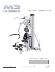
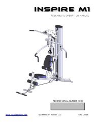
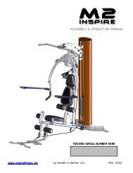
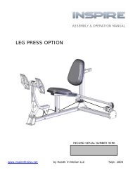
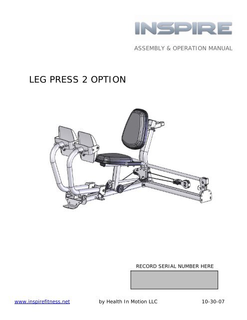
ASSEMBLY & OPERATION MANUAL<strong>LEG</strong> <strong>PRESS</strong> 2 <strong>OPTION</strong>RECORD SERIAL NUMBER HEREwww.inspirefitness.net by Health In Motion LLC 10-30-07
TABLE OF CONTENTSSection Description…………………………………………………..PageInstructions………………………………………………………………….. 1Tools Required……………………………………………………………… 1Parts & Hardware List………………………………………………….. 2Hardware Sizing Chart ………………………………………………… 3Cable Chart …………………………………………………………………. 4Assembly Instructions – attaching to M1 & M2 …………. 6Assembly Instructions – attaching to M3……….………….. 9Assembly Instructions – attaching to M4……….………….. 12Decal Reference……………………………………………………………. 21Decal Placement…………………………………………………………… 22General Maintenance Information…….………………………… 23Maintenance Schedule…….………………………………………….. 24Limited Warranty.………………………….……………………………. 25
BEFORE ASSEMBLING YOUR <strong>LEG</strong> <strong>PRESS</strong>IMPORTANT: Read this entire manual before attempting to build or useyour leg press. This manual contains step by step instructions for properassembly.Use the parts list included in this manual to verify that all parts areaccounted for before assembly. If any parts are missing, contact the retailerof this home gym for replacement parts. Or, call <strong>Inspire</strong> at 714-738-1729Service of your home gym should only be preformed by an authorizedINSPIRE retailer. Service preformed by anyone else can result in loss ofwarranty. Use only <strong>Inspire</strong> replacement parts on this machine. The use ofany other brand of parts can also result in a loss of warranty. If you needhelp finding an authorized retailer, please contact us directly:<strong>Inspire</strong> <strong>Fitness</strong>637 S State College Blvd.Fullerton, CA 92831Ph: 714-738-1729Fx: 714-738-1728www.inspirefitness.netTOOLS REQUIRED FOR ASSEMBLY• Standard socket set (including 9/16” and 3/4” sockets)• 9/16” wrench• 3/4” wrench• Adjustable wrench• Tape Measure• Rubber MalletPAGE 1
PARTS & HARDWARE LISTQtyItem Parts Description QtyRec'dItem Hardware Description Qty1 Leg Press Base 1 1 Bolt, 3/8-16 x 1" L Button Head 42 Press Arm, Left 1 2 Bolt, 3/8-16 x 1" L 23 Press Arm, Right 1 3 Bolt, 3/8-16 x 1 1/4" L 24 Foot Plate 2 4 Bolt, 3/8-16 x 1 3/4" L 25 Leg Press Attachment Arm 1 5 Bolt, 3/8-16 x 2" L 106 Back Pad Stem 1 6 Bolt, 3/8-16 x 2 1/2" L 47 Dual Pulley Mount 1 7 Bolt, 3/8-16 x 3 3/4" L 18 Seat Base 2 8 Bolt, 3/8-16 x 4 1/4" L 29 Handle Assy 1 9 Bolt, 3/8-16 x 4 3/4" L 110 Floating Dual Pulley Bracket 1 10 Bolt, 3/8-16 x 5" L 511 LP2-M4 Attachment Cable 1 11 Bolt, 3/8-16 x 8" L 112 Locking Rod 1 12 Bolt, 1/2-13 x 10 3/4" L 113 3 1/2" Pulley 914 LP2 Main Cable 1 13 3/8" Washer 4114 3/8" Small OD Washer 615 1/2" Washer 2QtyRec'd16 3/8-16 Locknut 1817 3/8-16 Thin Locknut 418 1/2-13 Locknut 119 Barrel Spacer, 5/16” Long 120 Barrel Spacer, 3/8” Long 421 Cable End with Bushing 222 Cable Adapter 123 Adjustable Bumper 224 6mm Allen Wrench 1Note: There may be extra hardware left over depending on which machinethe LP2 is attached.PAGE 2
HARDWARE SIZING CHART1" 2" 3" 4" 5" 6" 7"3/8" DIA. Bolt Allen Wrench1/2" DIA. Bolt1/2" Washer 3/8" Washer 3/8" Small OD Washer Cable End1/2" Locknut 3/8" Locknut 3/8" Thin Locknut 3/8" Barrel Spacer Bushing SleeveACTUAL PARTS MAY BE SMALLER OR LARGER THAN SHOWNPAGE 3
CABLE CHARTLP2 Main CableLP2-M4 Attachment CablePage 4
Assembly Instructions Leg Press 2Assembly Procedures for attaching LP2 to Home GymRefer to page 6 if attaching to M1 & M2Refer to page 9 if attaching to M3Refer to page 12 if attaching to M4Page 5
Assembly Procedure for attaching Leg Press 2 to M1 & M2NOTE: The Leg Press may be attached to either side of the Home Gym.The Illustrations show only one side.Lower CableSTEP 1Disconnect Cable &Remove Pulley 1Step 1: Remove Pulley 1 and disconnect Lower Cable from Home Gym. RetainPulley 1 and hardware for later use.Page 6
STEP 32 – 5” Hex Bolts 1 – 4 ¾” Hex Bolt4 – 3/8” Flat Washers 1 – 3/8” Flat Washer2 – 3/8” Lock NutsLeg Press BaseAttachment ArmSTEP 2Home Gym2 – 5” Hex Bolts4 – 3/8” Flat Washers2 – 3/8” Lock NutsStep 2: Attach Attachment Arm to Home Gym using: Two (3/8” x 5” Hex Bolts)(Finger Tighten Only)Four (3/8” Flat Washers)Two (3/8” Lock Nuts)Step 3: Attach Leg Press Base to Attachment Arm using: Two (3/8” x 5” Hex Bolts)(Wrench Tighten Bolts in Steps 2 & 3 Now) One (4 ¾” Hex Bolt)Five (3/8” Flat Washers)Two (3/8” Lock Nuts)Page 7
STEP 5 STEP 4Pulley-81 – 3 ½” Pulley 1 – 3 ½” Pulley1 – 2” Hex Bolt 1 – 2” Hex Bolt2 – 3/8” Flat Washers 2 – 3/8” Flat Washers1 – 3/8” Lock Nut 1 – 3/8” Lock NutPulley-9Floating DualPulley BracketSTEP 61 – 2” Hex Bolt2 – 3/8” Flat Washers1 – 3/8” Lock NutCableRetainerBoltSTEP 71 – 2” Hex Bolt2 – 3/8” Flat Washers1 – 3/8” Lock NutStep 4: Attach Pulley 8 to Attachment Arm using:One (3 ½” Pulley)Two (3/8” Flat Washers)One (3/8” x 2” Hex Bolt)One (3/8” Lock Nut)Step 5: Attach Pulley 9 to Floating Dual Pulley Bracket using:One (3 ½” Pulley)One (3/8” x 2” Hex Bolt)Two (3/8” Flat Washers)One (3/8” Lock Nut)Step 6: Thread Home Gym Lower Cable around Pulleys 8 & 9 and attach cable eyelet end toAttachment Arm (bottom hole) using:One (3/8” x 2” Hex Bolt)Two (3/8” Flat Washers)One (3/8” Lock Nut)Step 7: Attach Retainer Bolt to Attachment Arm using:One (3/8” x 2” Hex Bolt)Two (3/8” Flat Washers)One (3/8” Lock Nut)(Wrench Tighten Bolts in Steps 4-7 Now)(Make sure that the cable is routed between pulley 8 and the cable retainer bolt.)Assembly Steps are continued on page 15Page 8
Assembly Procedure for Attaching Leg Press 2 to M3NOTE: The Leg Press may be attached to either side of the Home Gym.The Illustrations show only one side.STEP 3Disconnect Middle CableMiddle CableSTEP 2Remove Pulley 1 & 1” Barrel Spacerfrom M3 Base FramePulley 1 &Barrel SpacerMain UprightRemove the Swivel Pulley Bracketfrom M3 Base FrameSwivel PulleySTEP 1Step 1: Remove the Swivel Pulley Bracket from the M3 Main Upright. Leave the cableconnected to the Swivel Pulley. Save Washers and Locknuts for later use.Step 2: Remove Pulley 1 and 1” long Barrel Spacer from M3 Main Upright.Save parts for later use.Step 3: Disconnect the Middle Cable from the Main Upright. Re-install Bolt, Washers andLocknut. Wrench tighten bolt.Page 9
5/16” Barrel SpacerSTEP 6 STEP 52 – 5” Hex Bolts 1 – 4 ¾” Hex Bolt 1 – 3 ¾” Hex Bolt4 – 3/8” Flat Washers 1 – 3/8” Flat Washer 1 – 5/16” Barrel Spacer2 – 3/8” Lock Nuts 2 – 3/8” Flat Washers1 – 3/8” Lock Nut1 – 3 ½” Pulley1 – 1” Barrel SpacerLeg Press BaseAttachment ArmHome GymSTEP 42 – 4 ¼” Hex Bolts4 – 3/8” Flat Washers2 – 3/8” Lock NutsStep 4: Attach Attachment Arm and Swivel Pulley Bracket to Home Gym using:Two (3/8” x 4 ¼” Hex Bolts)(Finger Tighten Only)Four (3/8” Flat Washers)Two (3/8” Lock Nuts)Step 5: Attach Attachment Arm to Main Upright using: One (3/8” x 3 ¾” Hex Bolt)Note: Re-install Pulley 1 & 1” Barrel Spacer One (5/16” Barrel Spacer)in original location Two (3/8” Flat Washers)(Finger Tighten Only) One (3/8” Lock Nut)One (3 ½” Pulley)One (1” Barrel Spacer)Step 6: Attach Leg Press Base to Attachment Arm using: Two (3/8” x 5” Hex Bolts)One (4 ¾” Hex Bolt)Five (3/8” Flat Washers)(Wrench Tighten all Bolts in Steps 4 - 6 Now) Two (3/8” Lock Nuts)Page 10
STEP 8 STEP 7Pulley-81 – 3 ½” Pulley 1 – 3 ½” Pulley1 – 2” Hex Bolt 1 – 2” Hex Bolt2 – 3/8” Flat Washers 2 – 3/8” Flat Washers1 – 3/8” Lock Nut 1 – 3/8” Lock NutPulley-9Floating DualPulley BracketSTEP 9CableRetainerBolt1 – 2” Hex Bolt2 – 3/8” Flat Washers1 – 3/8” Lock NutSTEP 102” Hex Bolt2 – 3/8” Flat Washers1 – 3/8” Lock NutStep 7: Attach Pulley 8 to Attachment Arm using:One (3 ½” Pulley)Two (3/8” Flat Washers)One (3/8” x 2” Hex Bolt)One (3/8” Lock Nut)Step 8: Attach Pulley 9 to Floating Dual Pulley Bracket using:One (3 ½” Pulley)One (3/8” x 2” Hex Bolt)Two (3/8” Flat Washers)One (3/8” Lock Nut)Step 9: Route Home Gym Middle Cable around Pulleys 8 & 9 and attach eyelet end toAttachment Arm (bottom Hole) using:One (3/8” x 2” Hex Bolt)Two (3/8” Flat Washers)One (3/8” Lock Nut)Step 10: Attach Retainer Bolt to Attachment Arm using:One (3/8” x 2” Hex Bolt)Two (3/8” Flat Washers)One (3/8” Lock Nut)(Wrench Tighten Bolts in Steps 7-10 Now)(Make sure that the cable is routed between pulley 8 and the cable retainer bolt.)Assembly Steps are continued on page 15Page 11
Assembly Procedure for Attaching Leg Press 2 to M4NOTE: The Leg Press can only be attached to the right sideof the Home Gym.STEP 1Floating PulleyBracketStep 1: Disconnect Floating Pulley Bracket from Main Upright and save removed hardware.Page 12
STEP 32 – 5” Hex Bolts 1 – 4 ¾” Hex Bolt4 – 3/8” Flat Washers 1 – 3/8” Flat Washer2 – 3/8” Lock NutsUse Upper HolesLeg Press BaseLeg PressAttachment ArmSTEP 22 – 1 ¼” Hex Bolts4 – 3/8” Flat Washers2 – 3/8” Lock NutsHome GymStep 2: Attach Leg Press Attachment Arm to Home Gym using:Two (3/8” x 1 ¼” Hex Bolts)Four (3/8” Flat Washers)(Finger Tighten Only) Two (3/8” Lock Nuts)Step 3: Attach Leg Press Base to Leg Press Attachment Arm using:Two (3/8” x 5” Hex Bolts)One (4 ¾” Hex Bolt)Five (3/8” Flat Washers)(Wrench Tighten Bolts in Steps 2 & 3 Now) Two (3/8” Lock Nuts)Page 13
STEP 4 STEP 51 – 3 ½” Pulley 1 – 3 ½” Pulley1 – 2” Hex Bolt 1 – 2” Hex Bolt2 – 3/8” Flat Washers 2 – 3/8” Flat Washers1 – 3/8” Lock Nut 1 – 3/8” Lock Nut1 – Cable AdapterPulley-8Cable AdapterFloating PulleyBracketPulley-9Floating DualPulley BracketSTEP 71 – 2” Hex Bolt2 – 3/8” Flat Washers1 – 3/8” Lock NutCableRetainerBoltSTEP 6STEP 81 – 3 ½” Pulley1 – 2” Hex Bolt 1 – 2” Hex Bolt2 – 3/8” Flat Washers 2 – 3/8” Flat Washers1 – 3/8” Lock Nut 1 – 3/8” Lock NutStep 4: Attach LP2-M4 Attachment Cable end to Floating Pulley Bracket using:One (3 ½” Pulley)One (Cable Adapter)One (3/8” x 2” Hex Bolt) Two (3/8” Flat Washers) One (3/8” Lock Nut)Step 5: Attach Pulley 8 to Attachment Arm using:One (3 ½” Pulley)One (3/8” x 2” Hex Bolt)Two (3/8” Flat Washers) One (3/8” Lock Nut)Step 6: Attach Pulley 9 to Floating Dual Pulley Bracket using:One (3 ½” Pulley)One (3/8” x 2” Hex Bolt)Two (3/8” Flat Washers) One (3/8” Lock Nut)Step 7: Route LP2-M4 Attachment Cable around Pulleys 8 & 9 and attach cable eyelet end toAttachment Arm (bottom hole) using:One (3/8” x 2” Hex Bolt) Two (3/8” Flat Washers) One (3/8” Lock Nut)Step 8: Attach Cable Retainer Bolt to Attachment Arm using:One (3/8” x 2” Hex Bolt) Two (3/8” Flat Washers) One (3/8” Lock Nut)(Wrench Tighten Bolts in Steps 4-8 Now)(Make sure that the cable is routed between pulley 8 and the cable retainer bolt.)Assembly Steps are continued on page 15Page 14
STEP 12 – 5” Hex Bolts Leg Press Base4 – 3/8” Flat Washers2 – 3/8” Lock NutsPress ArmsDual Pulley Mountshort end of tubefaces outwardSTEP 21 – 1/2” x 10 ¾” Hex Bolt2 – 1/2” Flat Washers1 – 1/2” Lock NutCaution: Press arms are unstable until thecables are attached. It is recommended tolay the press arms forward onto a protectivesurface until the cables are installed.Step 1: Attach Dual Pulley Mount to Leg Press Base using:Two (3/8” x 5” Hex Bolts)Four (3/8” Flat Washers)(Wrench Tighten Bolts)Two (3/8” Lock Nuts)Step 2: Attach Press Arms to Leg Press Base using:One (1/2” x 10 ¾” Hex Bolt)Two (1/2” Flat Washers)One (1/2” Lock Nut)(Wrench Tighten Bolts, Assembly Should Move Freely.)Note: Leg Press Arms angle outward from Leg Press Frame,short end of tube faces outward.Page 15
STEP 5STEP 62 – 3 ½” Pulleys 1 – 3 ½” Pulley2 – 2” Hex Bolts 1 – 2” Hex Bolt4 – 3/8” Flat Washers 2 – 3/8” Flat Washers2 – 3/8” Lock Nuts 1 – 3/8” Lock NutPulley-5 & 6Pulley-7CableSTEP 7Pulley-1 & 2STEP 3Pulley-3 & 4STEP 4Cable Endw/ Bushing1 – 8” Hex Bolt 2 – 3 ½” Pulleys 2 – 3 ½” Pulleys2 – 3/8” Small OD 2 – 2” Hex Bolts 2 –1 ¾” Hex BoltsWashers 4 – 3/8” Flat Washers 2 – 3/8” Flat Washers1 – 3/8” Lock Nuts 2 – 3/8” Lock NutsStep 3: Attach Pulleys 1 & 2 to Press Arms using:(Wrench Tighten Bolts)Step 4: Attach Pulleys 3 & 4 to Leg Press Base using:(Wrench Tighten Bolts)Step 5: Attach Pulleys 5 & 6 to Pulley Bracket using:(Wrench Tighten Bolts)Two (3 ½” Pulleys)Two (3/8” x 2” Hex Bolts)Four (3/8” Flat Washers)Two (3/8” Lock Nuts)Two (3 ½” Pulleys)Two (3/8” x 1 ¾” Hex Bolts)Two (3/8” Flat Washers)Two (3 ½” Pulleys)Two (3/8” x 2” Hex Bolts)Four (3/8” Flat Washers)Two (3/8” Lock Nuts)Step 6: Attach Pulley 7 to Floating Pulley Bracket using: One (3 ½” Pulley)One (3/8” x 2” Hex Bolt)Two (3/8” Flat Washers)(Wrench Tighten Bolts)One (3/8” Lock Nut)Step 7: Attach Main Cable by sliding end of cable thru slot of Cable End as shown,then slide Bushing into Cable End, attach Bolt. Route the Main Cable aroundPulleys 1, 3, 5 and thru Floating Pulley 7, continue routing cable around Pulleys 6,4, 2 and attach other end of cable to Cable End using:One (3/8” x 8” Hex Bolt)Two (3/8” Small OD Washers)(Wrench Tighten Bolts)One (3/8” Lock Nut)Page 16
STEP 8Orthopedic PadSeat BaseAssembledBack & Seat PadStep 8: Place Orthopedic Pad on Seat Base. Work the edge of pad into the grooveof the Seat base on all sides. Do not use sharp objects duringinstallation.Floating DualPulley BracketPress Arm StopsFloating Pulley StopStep 9: Cable AdjustmentScrew Press Arm Stops up or down to remove slack in Main Cable, tighten the Jam Nuts.Make sure both Press Arm Stops are adjusted to the same height; otherwise it might bedifficult to insert the Press Arm Locking Rod later. Next, adjust the Floating Pulley Stop outuntil it contacts the Floating Dual Pulley Bracket as shown in the diagram. Tighten jamnuts on the floating pulley stop. After first weeks use and as needed, adjust cable slackby alternately adjusting the Floating Pulley Stop and Press Arm Stops.Page 17
STEP 112 – 1” Hex Bolts2 – 3/8” Flat WashersBack Pad StemSTEP 102 – 2 ½” Hex Bolts4 – 3/8” Flat Washers2 – 3/8” Lock NutsBack PadSeat PadHandlesTo these sets of holesAttach Seat & HandleFor more Pre-StretchSTEP 122 – 2 ½” Hex Bolts2 – 3/8” Flat WashersTo these sets of holesAttach Seat & HandleFor more Leg RoomStep 10: Attach Handles to Leg Press Base using:(Wrench Tighten Bolts)Step 11: Attach Back Pad to Back Pad Stem using:(Wrench Tighten Bolts)Step 12: Attach Seat Pad to Leg Press Base using:(Wrench Tighten Bolts)Two (3/8” x 2 ½” Hex Bolts)Four (3/8” Flat Washers)Two (3/8” Lock Nuts)Two (3/8” x 1” Hex Bolts)Two (3/8” Flat Washers)Two (3/8” x 2 ½” Hex Bolts)Two (3/8” Flat Washers)Page 18
STEP 143/8” Barrel Spacer4 – 3/8” Barrel Spacers4 – 1” Button Head Bolts4 – 3/8” Small OD Washers4 – 3/8” Thin Lock NutsRubber Bumper PadsSTEP 13STEP 15Foot PlatesPress ArmsStep 13: Install Two Adjustable Bumpers.Step 14: Attach Foot Plates to Press Arms with Rubber Bumper Pads towards topas follows, tighten bolts first, then install and tighten Thin Lock Nuts using:(Tighten Bolts with 6mm Allen Wrench)Four (3/8” Barrel Spacers)Four (3/8” x 1” Button Head Bolts)Four (3/8” Small OD Washers)Four (3/8” Thin Lock Nuts)Step 15: Foot Plate Stop Adjustment:To adjust Foot Plate Stop angle, loosen jam nut, screw in or out theAdjustable Bumper, and retighten the Jam Nut.Page 19
Adjustable BumpersLocking RodStorageSTEP 16Step 16: Slide Locking Rod thru both Press Arm Brackets and tighten AdjustableBumpers against Locking Rod to secure Locking Rod in place.Store Locking Rod in Leg Press Base as shown when not in use.Page 20
DECAL REFERENCE714-738-1729PAGE 21
DECAL PLACEMENTSerial numberlabel (60 x 40)On base tube“WARNING, PINCHPOINTS” betweenpress pedals, onleg press arm (60 x40)PAGE 22
GENERAL MAINTENANCE INFORMATIONWarning: DO NOT place styrofoam or printed materials on theorthopedic seat pads. Over time, these may stick to the pads andmar the surface.Do not leave items sitting on the orthopedic seat pads, these padshave a special density that takes shape to objects and small objectswill leave imprints in the surface that may take time to come out.• Periodically inspect the cables, and cable ends, for splitting, cracking orfraying. Also, watch for bulging or flat areas in the cable.• Immediately replace cables at the first signs of damage or wear. Neveruse equipment with damaged or worn cables.• Cables naturally stretch over time, so check cable slack periodically andadjust cable tension as needed.• Regularly inspect product for loose hardware.• Do not use or store equipment outdoors.• Locate and familiarize yourself with all warning decals on the Leg Press.• Replace damaged or worn Seat Pads immediately.PAGE 23
MAINTENANCE SCHEDULEROUTINEClean: Seat PadsHOMEMAINTENANCEWEEKLYENTRY DATEInspect: Cables andtheir FittingsWEEKLYInspect: All Decals3 MONTHSInspect: All Nuts andBolts. Tighten if NeededLubricate: Seat Sleevesand all Plastic SlidesClean and Wax: AllGlossy FinishesReplace: Cables, andConnecting Parts3 MONTHS3 MONTHSYEARLY2 YEARSPAGE 24
LIMITED WARRANTYIn-Home Lifetime Warranty.This Warranty applies only in the United States to <strong>Inspire</strong> strength products manufactured or distributed by Health InMotion LLC. The warranty period to the original purchaser is lifetime of the original purchaser.Health In Motion warrants that the Product you have purchased for non-commercial, personal, family or householduse from Health In Motion LLC or from an authorized Health In Motion reseller is free from defects in materials orworkmanship under normal use during the warranty period. Your sales receipt, showing the date of purchase of theProduct, is your proof of the date of purchase. This warranty extends only to you, the original purchaser. It is nottransferable to anyone who subsequently purchases the Product from you. It excludes expendable parts such as paintand finish. This Warranty becomes VALID ONLY if the Product is assembled / installed according to the instructions /directions included with the Product.Replacement and repair of parts.During the warranty period Health In Motion will at no additional charge, repair or replace the Product if it becomesdefective, malfunctions, or otherwise fails to conform with this Warranty under normal non-commercial, personal,family, or household use. In repairing the product Health In Motion may replace defective parts with, at the option ofHealth In Motion, serviceable used parts that are equivalent to new parts in performance, or new parts. All exchangedparts and Products replaced under this warranty will become the property of Health In Motion. Health In Motionreserves the right to change manufacturers and or specification of any part to cover any existing warranty.Service procedures.To obtain warranty parts, you must return the parts to Health In Motion or an authorized Health In Motion retailer inits original container (or equivalent). You must pre-pay any shipping charges, taxes, or any other charges associatedwith transportation of the Product. In addition, you are responsible for insuring any Product shipped or returned. Youassume the risk of loss during shipment. You must present Health In Motion with proof-of-purchase documents(including the date of purchase, Model, and Serial Number). Any evidence of alteration, erasing or forgery of proof -of-purchase documents will be cause to void this Warranty.Conditions and Exceptions.This Warranty does not extend to any Product not purchased from Health In Motion LLC or from an authorized HealthIn Motion reseller. This Warranty does not extend to any Product that has been damaged or rendered defective; (a)as a result of accident, misuse, or abuse; (b) by the use of parts not manufactured or sold by Health In Motion; (c) bymodification of the Product; (d) as a result of service by anyone other than Health In Motion, or an authorized HealthIn Motion warranty service provider; (e) product that has not been properly maintained (follow maintenance schedulefound on product). Should any product submitted for Warranty service be found to be ineligible, an estimate of repaircost will be furnished and the repair will be made if requested by you upon Health In Motion receipt of payment oracceptable arrangement of payment.DisclaimerEXCEPT AS EX<strong>PRESS</strong>LY SET FORTH IN THIS WARRANTY HEALTH IN MOTION MAKES NO OTHER WARRANTIES;EX<strong>PRESS</strong>ED OR IMPLIED INCLUDING ANY IMPLIED WARRANTIES OF MERCHANTABILITY AND FITNESS FOR APARTICULAR PURPOSE. HEALTH IN MOTION EX<strong>PRESS</strong>LY DISCLAIMS ALL WARRANTIES NOT STATED IN THISWARRANTY. ANY IMPLIED WARRANTIES THAT MAY BE IMPOSED BY LAW ARE LIMITED TO THE TERMS OF THISWARRANTY. NEITHER HEALTH IN MOTION NOR ANY OF ITS AFFILIATES SHALL BE RESPONSIBLE FOR INCIDENTALOR CONSEQUENTIAL DAMAGES. HEALTH IN MOTION IS NOT RESPOSIBLE FOR THE REPAIR OR REPLACEMENT OFANY PARTS THAT HEALTH IN MOTION DETERMINES HAVE BEEN SUBJECTED AFTER THE DATE OF MANUFACTURE TOALTERATION, NEGLECT, ABUSE, MISUSE, NORMAL WEAR & TEAR, ACCIDENT, DAMAGE DURING TRANSIT ORINSTALLATION, FIRE, FLOOD, OR ANY ACT OF GOD. SOME STATES DO NOT ALLOW LIMITATIONS ON HOW LONG ANIMPLIED WARRANTY LASTS OR THE EXCLUSION OR LIMITATION OF INCIDENTAL OR CONSEQUENTIAL DAMAGES, SOTHE ABOVE LIMITATIONS OR EXCLUSION MAY NOT APPLY TO YOU. This Warranty gives you specific legal rights andyou may also have other rights that may vary from state to state. This is the only express warranty applicable toHealth In Motion’s “<strong>Inspire</strong>” branded strength products. Health In Motion neither assumes nor authorizes anyone toassume for it any other express warranty.PAGE 25