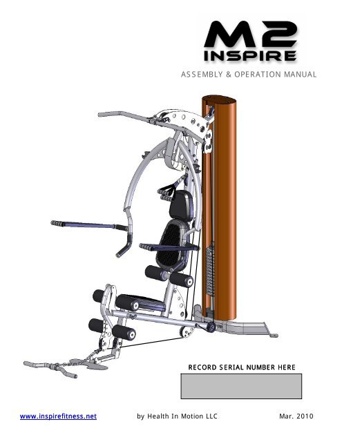
ASSEMBLY & OPERATION MANUAL - Inspire Fitness
ASSEMBLY & OPERATION MANUAL - Inspire Fitness
ASSEMBLY & OPERATION MANUAL - Inspire Fitness

Create successful ePaper yourself
Turn your PDF publications into a flip-book with our unique Google optimized e-Paper software.
TABLE OF CONTENTSSection Description…………………………………………………….PageImportant Safety Instructions………………………………………. 1Tools Required………………………………………………………………… 1Parts List…………………………………………………………………………. 2Hardware List…………………………………………………………………. 2Hardware Chart …………………………………………………………….. 3Cable Chart ……………………………………………………………………. 5Assembly Instructions……………………………………………………. 6Decal Reference……………………………………………………………… 26Decal Placement……………………………………………………………… 28Accessories……………………………………………………………………… 29General Maintenance Information…….…………………………… 30Maintenance Schedule…….……………………………………………… 31Limited Warranty…………………………………………………………….. 32
M2 PARTS & HARDWARE LISTItem Parts Description Qty Qty Rec'd Item Hardware Description Qty Qty Rec'd1 Base Beam 1 1 Bolt, 1/4-20 x 3/8" L (Phillips head) 12 Rear Base 1 2 Bolt, 1/4-20 x 3" L (Button Head) 13 Backing Plate 1 3 Bolt, 5/16-18 x 1-1/4" L (Shoulder) 34 Foot Plate 1 4 Bolt, 3/8x16 x 1" L (Flat Head) 85 Main Upright 1 5 Bolt, 3/8-16 x 1/2" L (Button Head) 26 Top Beam Plate 2 6 Bolt, 3/8-16 x 1" L 67 Press Arm Mount 1 7 Bolt, 3/8-16 x 1 3/4" L 78 Press Arm Cover Plate 1 8 Bolt, 3/8-16 x 2" L 49 Press Arm Bearing Assembly 2 9 Bolt, 3/8-16 x 2 1/2" L 110 Press Arm Assembly 1 10 Bolt, 3/8-16 x 2 3/4" L 211 Backpad Tilt Frame 1 11 Bolt, 3/8-16 x 3" L 512 Lat Bar Holder 2 12 Bolt, 3/8-16 x 3 3/4" L 813 Guide Rod 2 13 Bolt, 3/8-16 x 4" L 614 Shroud Plate 1 14 Bolt, 3/8-16 x 4 3/4" L 115 Shroud Plate Assembly 1 15 Bolt, 3/8-16 x 5" L 116 Floating Pulley Plate 2 16 Bolt, 3/8-16 x 5 3/4" L 117 Floating Pulley Bracket 1 17 Bolt, 1/2-13 x 6" L 118 Top Weight/Selector Stem 1 18 Setscrew, 1/4-20 x 3/16" long 219 Weight Stack Riser 220 Weight Stack Number 1 19 1/4" Washer 121 Rubber Donut 2 20 3/8" Washer 6522 Roller Tube 3 21 3/8" Washer, small OD 623 Covered Foam Roller 6 22 1/2" Washer 224 Aluminum Endcap 625 Large Plastic Washer 6 23 1/4-20 Flat Head Nut 126 Seat Stem 1 24 5/16-18 Locknut 327 Seat Base 2 25 3/8-16 Locknut 3628 Head Pad 1 26 1/2-13 Locknut 129 Upper Cable 130 Middle Cable 1 27 Spacer Tube, 3" Long 131 Lower Cable 1 28 Step Spacer, 1" Long 832 D handle/Ab Strap 2 29 Step Spacer, 1/2" Long 233 Ankle Strap 1 30 Barrel Spacer, 1" Long 234 Revolving Aluminum Lat Bar 1 31 Barrel Spacer, 5/8" Long 235 Revolving Aluminum Curl Bar 136 Fabric Shroud 1 32 Cable Adapter 137 Guide Rod Lube 2 33 "U" Bracket Cable End 338 Touch-up Paint 1 34 Cable Ball 335 Spring Clip 439 3 1/2" Pulley 14 36 Chain 140 4 1/2" Pulley 2 37 Weight Pin 141 4 1/2" Wide Pulley 1 38 3 mm Wrench 139 5 mm Wrench 140 6 mm Wrench 1PAGE 2
HARDWARE CHART1" 2" 3" 4" 5" 6" 7"3/8" DIA. Bolt 5/16"DIA. Shoulder Bolt Button Head Bolt1/2" DIA. Bolt 3/8"DIA.Flat Head Bolt Phillips Head Screw3/8" Washer 3/8" Washer Sm. O.d. 1/2" Washer 1/4" Washer1/2" Locknut 3/8" Locknut 5/16" Locknut Flat Head NutACTUAL PARTS MAY BE SMALLER OR LARGER THAN SHOWNPAGE 3
CABLE CHARTUPPER CABLEMIDDLE CABLELOWER CABLEPAGE 5
<strong>ASSEMBLY</strong> INSTRUCTIONSPAGE 6
Foot PlateMain BaseNOTE: UseOutside Holesin Step 1.STEP 21 - 3” Hex Bolt2 - 3/8” Small OD Washers1 - 3/8” Lock NutDo Not Over TightenSTEP 12 - 3” Hex Bolts4 - 3/8” Flat Washers Backing Plate2 - 3/8” Lock NutsRear BaseSTEP 1: Attach Rear Base to Main Base using:Note: Wrench tighten nowNote: Use outside holes in Step 1Two (3/8” x 3” Hex Bolt)Four (3/8” Flat Washers)Two (3/8” Lock Nuts)One (8 ¼” Backing Plate)STEP 2: Attach Foot Plate to Main Base using:Note: Wrench tighten now butdo not over tighten.Foot plate must flip up easilyOne (3/8” x 3” Hex Bolt)Two (3/8” Small OD Washers)One (3/8” Lock Nut)Page 7
Guide RodsSTEP 4Shroud PlateHoles must line upSTEP 32 - 3 ¾” Hex Bolts4 - 3/8” Flat Washers2 - 3/8” Lock NutsFINGER TIGHTEN ONLY!STEP 3: Attach Guide Rods to Rear Base using:Note: Finger tighten onlyNote: If these bolts do not go in smoothlyLoosen bolts from step 1.Two (3/8” x 3 ¾” Hex Bolts)Four (3/8” Flat Washers)Two (3/8” Lock Nuts)STEP 4: Slide Shroud Plate down Guide Rods onto Rear Base. Make sure that center hole inShroud Plate lines up with hole between Guide Rods in Main Base.Page 8
STEP 6IMPORTANT!Guide Rods must be2 - 1 ¾” Hex Bolts in Front of plate.4 - 3/8” Flat Washers2 - 3/8” Lock NutsFINGER TIGHTEN ONLYMain UprightSTEP 52 - 4” Hex Bolts4 - 3/8” Flat Washers2 - 3/8” Lock NutsFINGER TIGHTEN ONLYStep 5: Attach Main Upright to Main Base using:Note: Finger Tighten OnlyStep 6: Attach Guide Rods to Main Upright using:Note: Finger Tighten OnlyTwo (3/8” x 4” Hex Bolts)Four (3/8” Flat Washers)Two (3/8” Lock Nuts)Two (3/8” x 1 ¾” Hex Bolts)Four (3/8” Flat Washers)Two (3/8” Lock Nuts)Page 9
Note: Attach left and right top beams with “<strong>Inspire</strong>” logo facing out.Right Top Beam PlateLeft Top Beam Plate1” Bolt1” BoltSTEP 72 - 4” Hex Bolts2 - 1” Hex Bolts6 - 3/8” Flat Washers2 - 3/8” Lock NutsFINGER TIGHTEN ONLYPress Arm MountStep 7: Attach Left and Right Top Beam Plates to Main Upright using:Two (3/8” x 4” Hex Bolts)Two (3/8” x 1” Hex Bolts)Six (3/8” Flat Washers)Note: Finger Tighten OnlyTwo (3/8” Lock Nuts)NOTES: Hang Press Arm Mount from Top Beam Plates as Plates are attached.Page 10
Press Arm BearingsUse Small OD Washers on theOutside of the Press Arm BearingsSTEP 9STEP 82 – ½” Button Head Bolts2 – 3/8” Flat Washers4 – 1” Hex Bolts4 – 3/8” Small ODWashers4 – 3/8” Flat Washers4 – 3/8” Lock NutsPress Arm MountStep 8: Attach Press Arm Bearings to Top Beam Plates using:Note: Finger Tighten OnlyFour (1" Hex Bolts)Four (3/8” Small OD Washers)Four (3/8” Flat Washers)Four (3/8” Lock Nuts)Step 9: Attach Press Arm Mount to Press Arm Bearings Using:Note: Finger Tighten OnlyTwo (1/2” Button Head Bolts)Two (3/8” Flat Washers)Page 11
STEP 10Install Four PulleysPULLEY 11 - 3 ¾” Hex Bolt2 - 1” Step Spacers1 - 3/8” Lock Nut 4 ½” Pulley1 - 2” Hex Bolt2 - 3/8” Flat Washers1 - 3/8” Lock NutPULLEY 23 ½” PulleysPULLEY 3PULLEY 42 - 3 ¾” Hex Bolts4 - 1” Step Spacers2 - 3/8” Lock NutsStep 10: Attach Pulley 1 to Main Upright using:Attach Pulley 2 to Main Upright using:Attach Pulleys 3 & 4 to Main Upright using:Page 12One (4 ½” Pulley)One (3 ¾” Hex Bolt)Two (1” Step Spacers)One (3/8” Lock Nut)One (3 ½” Pulley)One (2” Hex Bolt)Two (3/8” Flat Washers)One (3/8” Lock Nut)Two (3 ½” Pulleys)Two (3 ¾” Hex Bolts)Four (1” Step Spacers)Two (3/8” Lock Nuts)
STEP 132 – Lat Bar Holders1 – 4 ¾” Hex Bolt1 – 3” Spacer Tube2 – 3/8” Flat Washers1 – 3/8” Lock NutSTEP 121 – 4 ½” Wide Pulley Pulley 61 – 4” Hex Bolt2 – 5/8” Barrel Spacers2 – 3/8” Flat Washers1 – 3/8” Lock Nut Pulley 5STEP 111 – 3 ½” Pulley1 – 4” Hex Bolt2 – 1” Barrel Spacers2 – 3/8” Flat Washers1 – 3/8” Lock NutStep 11: Attach Pulley 5 to Top Beam using:Note: Finger Tighten OnlyStep 12: Attach Pulley 6 to Top Beam using:Note: Finger Tighten OnlyStep 13: Attach Lat Bar Holders to Top Beam using:NOTE: Tighten all bolts in steps 8 – 13 Now.Do Not Over TightenPage 13One (3 ½” Pulley)One (3/8” x 4” Hex Bolt)Two (1” Barrel Spacers)Two (3/8” Flat Washers)One (3/8” Lock Nut)One (4 ½” Wide Pulley)One (3/8” x 4” Hex Bolt)Two (5/8” Barrel Spacers)Two (3/8” Flat Washers)One (3/8” Lock Nut)Two (Lat Bar Holders)One (3/8” x 4 ¾” Hex Bolt)One (3” Spacer Tube)Two (3/8” Flat Washers)One (3/8” Lock Nut)
STEP 14Install Six Pulleys &One Cable Retaining BoltTIGHTEN THESE BOLTS NOWPULLEY 71 – 4 ½” Pulley1 – 3 ¾” Hex Bolt2 – 1” Step Spacers1 – 3/8” Lock Nut1 – 3 ½” Pulley1 – 2” Hex Bolt2 – 3/8” Flat Washers1 – 3/8” Lock Nut 1 – 3 ½” Pulley1 – 1 ¾” Hex Bolt2 – 3/8” Flat Washers1 – 3/8” Lock NutPULLEY 12PULLEY 8PULLEY 9PULLEY 10NOTE: If you purchased leg press option,refer to leg press ownersPULLEY 11 manual before attaching pulley 11CABLE RETAINING BOLT1 – 2 ¾” Hex Bolt 1 – 3 ½” Pulley 1 – 3 ½” Pulley 1 – 3 ½” Pulley2 – 3/8” Flat Washers 1 – 2 ¾” Hex Bolt 1 – 2” Hex Bolt 1 – 5 ¾” Hex Bolt1 – 3/8” Lock Nut 2 – ½” Step Spacers 2 – 3/8” Flat Washers 2 – 3/8” Flat Washers1 – 3/8” Lock Nut 1 – 3/8” Lock Nut 1 – 3/8” Lock NutStep 14:Attach Pulley 7 using: One (3 ¾” Hex Bolt)Two (1” Step Spacers)One (3/8” Lock Nut)Attach Pulley 8 using: One (2” Hex Bolt)Two (3/8” Flat Washers)One (3/8” Lock Nut)Attach Pulley 9 using: One (2 ¾” Hex Bolt)Two (½” Step Spacers)One (3/8” Lock Nut)Attach Pulley 10 using: One (2” Hex Bolt)Two (3/8” Flat Washers)One (3/8” Lock Nut)Attach Pulley 11 using: One (5 ¾” Hex Bolt)Two (3/8” Flat Washers)One (3/8” Lock Nut)Attach Pulley 12 using: One (1 ¾” Hex Bolt)Two (3/8” Flat Washers)One (3/8” Lock Nut)Attach Cable Retaining Bolt using: One (2 ¾” Hex Bolt)Two (3/8” Flat Washers)Page 14One (3/8” Lock Nut)
NOTE: Once Assembled, slide rubberwasher against plastic ballSTEP 161 – Plastic Ball1 – Cable “U” Bracket1 – 1 ¼ “ Shoulder Bolt1 – Spring Clip1 – 5/16” Lock NutPulley 13NOTE: CABLE GOES INSIDE FRAME TUBESTEP 15Press Arm Mount2 – 3 ½” Pulleys Pulley 142 – 3” Hex Bolts4 – 3/8” Flat Washers2 – 3/8” Lock NutsStep 15:Begin by running upper cable from back of machine to frontas shown in the diagram. Next, slide pulleys 13 & 14 into thePress Arm Mount as cable is routed. Secure Press Arm Pulleys using:Two (3” Hex Bolts)Wrench Tighten Now.Four (3/8” Flat Washers)Two (3/8” Lock Nuts)Step 16: Assemble Cable End by sliding one plastic ball onto the end of the cable. Next slide thecable end into the side of the cable “U” bracket. Finally, attach spring clip to “U” bracket using a1 ¼” shoulder bolt and 5/16” lock nut. Wrench Tighten Now.Page 15
STEP 19STEP 181 – Floating Pulley Bracket1 – 3 ½” Pulley 2 – Floating Pulley Plates1 – Cable Adapter 2 – 3 ½” Pulleys1 – 2” Hex Bolt 2 – 1 3/4” Hex Bolts2 – 3/8” Flat Washers 4 – 3/8” Washers1 – 3/8” Lock Nut 2 – 3/8” Lock NutsPulley 16Pulley 15Pulley PlatePulley 17STEP 171 – 5” Hex Bolt3 – 3/8” Flat Washers1 – 3/8” Lock NutPulley 11Step 17: Attach the Middle Cable to the Main Base using:Finger Tighten OnlyStep 18: Assemble the Pulley Plates using:Wrench Tighten NowOne (3/8” x 5” Hex Bolt)Three (3/8” Flat Washers)One (3/8” Lock Nut)Two (Floating Pulley Plates)Two (3 ½” Pulleys)Two (1 ¾” Hex Bolts)Four (3/8” Flat Washers)Two (3/8” Lock Nuts)Step 19: Attach Middle Cable to Floating Pulley Bracket using: One (Cable Adapter)Wrench Tighten NowOne (3 ½” Pulley)One (3/8” x 2” Hex Bolt)Two (3/8” Flat Washers)One (3/8” Lock Nut)Page 16
STEP 201 – Plastic Ball1 – Cable “U” Bracket1 – 1 ¼ “ Shoulder Bolt1 – Spring Clip1 – 5/16” Lock NutSTEP 221 – Plastic Ball1 – Cable “U” Bracket1 – 1 ¼ “ Shoulder Bolt1 – Spring Clip1 – 5/16” Lock NutSTEP 21Route Lower CablePulley 10Cable Retainer PinStep 20: Assemble Cable End as donein step 16 using:Wrench Tighten NowOne (Plastic Ball)One (Cable “U” Bracket)One (1 ¼” Shoulder Bolt)One (Spring Clip)One (5/16” Lock Nut)Step 21: Route Lower Cable from top to bottomNOTE: Make sure cable is routed between pulley 10 and cable retainer pin.Step 22: Assemble Cable End as donein step 16 using:Wrench Tighten NowOne (Plastic Ball)One (Cable “U” Bracket)One (1 ¼” Shoulder Bolt)One (Spring Clip)One (5/16” Lock Nut)Page 17
Note: To assemble orthopedic pads, place pad on Seat Base.Work the edge of pad into the groove of the Seat Baseon all sides.Do not use sharp objects during installation.Seat BaseSTEP 28Seat Stem2 – 1 ¾” Hex Bolts2 – 3/8” Flat WashersSTEP 26STEP 29Assemble Roller Tubes& Roller PadsLeg ExtensionArmMain Upright2 – 3 ¾” Hex Bolt2 – 3/8 Flat WashersSTEP 272 – 1” Flat Head BoltsNOTE: Roller tube must gothrough tube in the LegExtension ArmStep 26: Attach Head Pad to Main Upright using:Wrench Tighten Now, Do Not Over TightenStep 27: Attach Seat Base to Backpad Tilt Fame using:Wrench Tighten Now, Do Not Over TightenStep 28: Attach Seat Base to Seat Stem using:Wrench Tighten Now, Do Not Over TightenTwo (3/8” x 3 ¾” Hex Bolts)Two (3/8” Flat Washers)Two (3/8” x 1” Flat Head Bolts)Two (3/8” x 1 ¾” Hex Bolts)Two (3/8” Flat Washers)Step 29: Slide Roller Tubes into Seat Stem and Leg Extension Arm as shown in diagram. Next,slide Plastic Washers onto Roller Tubes, followed by Roller Pads. Finally, secure RollerPads with Aluminum Endcaps and 1” Flat Head Bolts. Wrench Tighten NowPage 19
STEP 311 – ¼” Phillips Head Screw1 – ¼” Flat WasherSTEP 301 – 6” Hex Bolt2 – ½” Flat Washers1 – ½” Lock NutStep 30:Attach Press Arm to Press Arm Mount using:Wrench Tighten NowOne (1/2” x 6” Hex Bolt)Two (1/2” Flat Washers)One (1/2” Lock Nut)Step 31:Attach Press Arm Plate to Press Arm Mount Using: One (¼” Phillips Screw)Wrench Tighten NowOne (¼” Flat Washer)Page 20
STEP 32Remove Bolts from Guide RodsIMPORTANT! Cable Bolt must be fully threadedinto Selector Stem with Jam Nut tightened securelybefore using. Failure to do so may cause cable tocome loose from weights and cause injury.STEP 33Install Weight Stack Risers,Rubber Donuts, Weight Stack,Top Weight/Selector Stem(In That Order)INSTALL WEIGHT STICKERS NOWFront of weight plate has recessedarea for weight plate numberBottom of weight plate hasthree feetShroud PlateStep 32: Remove the bolts that connect the top of the Guide Rods to the Main Upright.NOTE: Before beginning Step 33: If optional 200 lb. heavy weight stack is being assembled, eliminate theweight stack risers. (This space will be taken up by 5 extra weight plates.)Step 33: Slide Weight Stack Risers down the Guide Rods and onto the Shroud Plate. Next slidethe Rubber Donuts down the Guide Rods until sitting on Weight Stack Risers. Next slide eachplate down the Guide Rods until all 15 Weight Plates are resting on the Rubber Donuts.Be sure that all weight plates are facing forward. (Front of plates is signified by recessed area forweight stack numbers). Next slide Top Weight/Selector Stem down guide rods and onto weightstack. Finally connect top cable to top weight by threading cable bolt into it.IMPORTANT!! Cable bolt must be fully threaded into Selector Stem with Jam Nuttightened securely before using. Failure to do so may cause the cable to come loose fromthe weights and cause injury.Page 21
STEP 342 – 1 ¾” Hex Bolts4 – 3/8” Flat Washers2 – 3/8” Lock NutsNote: Be sure guide rods are positionedin front of plate.Shroud Plate AssemblySTEP 351 – 2 ½” Hex Bolt2 – 3/8” Flat Washers1 – 3/8” Lock NutStep 34: Secure Guide Rods and Shroud Plate Assembly Two (3/8”x1 ¾” Hex Bolts)to Main Upright using:Four (3/8” Flat Washers)Two (3/8” Lock Nuts)Step 35: Secure Bottom Shroud Plate to Rear Base using: One (3/8”x2 ½” Hex Bolt)Two (3/8” Flat Washers)Note: If heavy stack has been installed, bolt in step One (3/8” Lock Nut)35 must be installed from the bottom.Note: Tighten bolts in Steps 34, 35 and Steps 3, 5, 7, and 17 now.Page 22
STEP 36Install Fabric ShroudTop Shroud PlateShroud Plate Adjustment BoltsBottom ShroudPlateStep 36: To install Fabric Shroud, start at the front of the top shroud plate and wrap the edgeof the fabric shroud around the shroud plate. Pull tight as you wrap and make sure thatthe velcro rim on the fabric shroud seals firmly to the velcro rim on the Shroud Plate.Next, Do the same for the bottom of the fabric shroud around the bottom shroud plate.Be sure to pull tight as fabric shroud is wrapped.If ripples appear on the fabric shroud, undo the top of the shroud and re-wrap, pullingup as the shroud is wrapped. This should give a nice smooth consistency to the shroud.(If necessary, shroud can be tightened by adjusting the Shroud Plate Adjustment Bolts.)Page 23
STEP 37STEP 38Note: When not in use, EZ curl bar orLat Bar can be stored in theaccessory holder.STEP 39Step 37: Attach Lat Bar to High Pulley with Spring ClipStep 38: Attach “D” Handles to Mid Pulley with Spring ClipStep 39: Attach Revolving EZ Curl Bar to Chain, then Chain to Low Pulley with Spring ClipsPage 24
STEP 41Press Arm StopCable BoltSTEP 40Jam NutSelector StemStep 40: Verify that Cable Bolt is threaded at least ½” into Selector Stem. Wrenchtighten Jam Nut.NOTE: At this point it is necessary to seat the cables. Start by verifying that cables arecentered in the grooves of all pulleys. Next, select a weight you cancomfortably handle on the bench press. Perform a seated bench press and holdthe first repetition at arms length. Now, lightly bounce the weight up and downfor about 5 seconds. This will seat the cables into the pulleys and prepare thegym for Step 41.Step 41: Eliminate cable slack by adjusting Press Arm Stop counter clockwise. WrenchTighten Jam Nut.Page 25
DECAL REFERENCEPAGE 26
DECAL REFERENCEPAGE 27
DECAL PLACEMENTGlobe Logo Label(50mm) Round“<strong>Inspire</strong>” logo on bothsides of the top beam(127mm x 38mm)“<strong>Inspire</strong> M2”below logolabel (50 x 38)“Do Not Hang FromPress Arm” belowM2 label (50mm)Round“WARNING Use onlygenuine INSPIREreplacement parts” on sideof upright. (40 x 170)“WARNING,PINCH POINTS”on top of basetube between LEflats (60 x 40)“This productPatent Pending”placed just abovethe “Notice” label(60 x 40)“NOTICE” onside of upright,beside head pad(40 x 170)Weight # labels(1 – 21),included withmanual. Silver#’s on blackbackground. (18x 25)“DANGER, THIS PRODUCTNOT DESIGNED FORCOMMERCIAL USE” onbase in front of serial #label (80 x 40)Serial # label(60 x 40)PAGE 28
ACCESSORIES• Exercise Wall Chart• Lat Bar• Revolving EZ Curl Bar• Ankle Strap• Abdominal Strap HandleHOME GYM OPTIONS• Heavy Stack (50lbs.)• Colored Orthopedic Pads• Colored Shroud• Leg Press• Ab Crunch BarTraining TipsCONSULT A PHYSICIAN BEFORE STARTING ANY EXERCISE PROGRAM1. Always warm up before you start weight training. This helps getyour muscles warm and prevents injury. You can warm up with lightcardio or by doing a light set of each exercise before going to heavierweights.2. Control the weight. Always work with a weight that you can handlethrough a full range of motion. Slow and steady movements arerecommended.3. Breathe. Don’t hold your breath during your set. Holding yourbreath builds internal pressure which increases your change for brokenblood vessels, as well as a hernia.4. Sit up straight. Pay attention to your posture and keep everythingstraight. Engage your abs in every movement to keep balanced andprotect your spine.PAGE 29
GENERAL MAINTENANCE INFORMATIONWarning: DO NOT place styrofoam or printed materials on theorthopedic seat pads. Over time, these may stick to the pads andmar the surface.Do not leave items sitting on the orthopedic seat pads, these padshave a special density that takes shape to objects and small objectswill leave imprints in the surface that may take time to come out.• Periodically inspect the cables for splitting, cracking or fraying. Also,watch for bulging or flat areas in the cable.• Immediately replace cables at the first signs of damage or wear. Neveruse equipment with damaged or worn cables.• Cables naturally stretch over time, so check cable slack periodically andadjust cable tension as needed.• Regularly inspect product for loose hardware.• Do not use or store equipment outdoors.• Inspect snap links, swivels, handles and weight stack pin for wear ordamage. If wear or damage exists, replace immediately.• Locate and familiarize yourself with all warning decals on the home gym.• Replace damaged or worn upholstery immediately.• Periodically wipe down guide rods with a dry cloth and re-apply a thin coatof a teflon-based lubricant.PAGE 30
MAINTENANCE SCHEDULEROUTINEInspect: Links, Pull Pins,Spring Clips, Swivels,Weight Stack PinsClean: UpholsteryHOMEMAINTENANCEWEEKLYWEEKLYENTRY DATEInspect: Cables andtheir FittingsInspect: Tautness of allShroudsInspect: Accessory Barsand HandlesWEEKLYWEEKLY3 MONTHSInspect: All Decals3 MONTHSInspect: All Nuts andBolts. Tighten if NeededInspect: Anti-SkidsurfacesClean and Lubricate:Guide Rods with a Teflonbased lubricantLubricate: Seat Sleevesand all Plastic SlidesClean and Wax: AllGlossy FinishesReplace: Cables, Beltsand Connecting Parts3 MONTHS3 MONTHS3 MONTHS3 MONTHSYEARLY2 YEARSPAGE 31
LIMITED WARRANTYIn-Home Lifetime Warranty.This Warranty applies only in the United States to <strong>Inspire</strong> strength products manufactured or distributed by Health InMotion LLC. The warranty period to the original purchaser is lifetime of the original purchaser.Health In Motion warrants that the Product you have purchased for non-commercial, personal, family or householduse from Health In Motion LLC or from an authorized Health In Motion reseller is free from defects in materials orworkmanship under normal use during the warranty period. Your sales receipt, showing the date of purchase of theProduct, is your proof of the date of purchase. This warranty extends only to you, the original purchaser. It is nottransferable to anyone who subsequently purchases the Product from you. It excludes expendable parts such as paintand finish. This Warranty becomes VALID ONLY if the Product is assembled / installed according to the instructions /directions included with the Product.Replacement and repair of parts.During the warranty period Health In Motion will at no additional charge, repair or replace the Product if it becomesdefective, malfunctions, or otherwise fails to conform with this Warranty under normal non-commercial, personal,family, or household use. In repairing the product Health In Motion may replace defective parts with, at the option ofHealth In Motion, serviceable used parts that are equivalent to new parts in performance, or new parts. All exchangedparts and Products replaced under this warranty will become the property of Health In Motion. Health In Motionreserves the right to change manufacturers and or specification of any part to cover any existing warranty.Service procedures.To obtain warranty parts, you must return the parts to Health In Motion or an authorized Health In Motion retailer inits original container (or equivalent). You must pre-pay any shipping charges, taxes, or any other charges associatedwith transportation of the Product. In addition, you are responsible for insuring any Product shipped or returned. Youassume the risk of loss during shipment. You must present Health In Motion with proof-of-purchase documents(including the date of purchase, Model, and Serial Number). Any evidence of alteration, erasing or forgery of proof -of-purchase documents will be cause to void this Warranty.Conditions and Exceptions.This Warranty does not extend to any Product not purchased from Health In Motion LLC or from an authorized HealthIn Motion reseller. This Warranty does not extend to any Product that has been damaged or rendered defective; (a)as a result of accident, misuse, or abuse; (b) by the use of parts not manufactured or sold by Health In Motion; (c) bymodification of the Product; (d) as a result of service by anyone other than Health In Motion, or an authorized HealthIn Motion warranty service provider; (e) product that has not been properly maintained (follow maintenance schedulefound on product). Should any product submitted for Warranty service be found to be ineligible, an estimate of repaircost will be furnished and the repair will be made if requested by you upon Health In Motion receipt of payment oracceptable arrangement of payment.DisclaimerEXCEPT AS EXPRESSLY SET FORTH IN THIS WARRANTY HEALTH IN MOTION MAKES NO OTHER WARRANTIES;EXPRESSED OR IMPLIED INCLUDING ANY IMPLIED WARRANTIES OF MERCHANTABILITY AND FITNESS FOR APARTICULAR PURPOSE. HEALTH IN MOTION EXPRESSLY DISCLAIMS ALL WARRANTIES NOT STATED IN THISWARRANTY. ANY IMPLIED WARRANTIES THAT MAY BE IMPOSED BY LAW ARE LIMITED TO THE TERMS OF THISWARRANTY. NEITHER HEALTH IN MOTION NOR ANY OF ITS AFFILIATES SHALL BE RESPONSIBLE FOR INCIDENTALOR CONSEQUENTIAL DAMAGES. HEALTH IN MOTION IS NOT RESPOSIBLE FOR THE REPAIR OR REPLACEMENT OFANY PARTS THAT HEALTH IN MOTION DETERMINES HAVE BEEN SUBJECTED AFTER THE DATE OF MANUFACTURE TOALTERATION, NEGLECT, ABUSE, MISUSE, NORMAL WEAR & TEAR, ACCIDENT, DAMAGE DURING TRANSIT ORINSTALLATION, FIRE, FLOOD, OR ANY ACT OF GOD. SOME STATES DO NOT ALLOW LIMITATIONS ON HOW LONG ANIMPLIED WARRANTY LASTS OR THE EXCLUSION OR LIMITATION OF INCIDENTAL OR CONSEQUENTIAL DAMAGES, SOTHE ABOVE LIMITATIONS OR EXCLUSION MAY NOT APPLY TO YOU. This Warranty gives you specific legal rights andyou may also have other rights that may vary from state to state. This is the only express warranty applicable toHealth In Motion’s “<strong>Inspire</strong>” branded strength products. Health In Motion neither assumes nor authorizes anyone toassume for it any other express warranty.PAGE 32