Kuda data sheet OLD.bak - Kaman Precision | Position sensors
Kuda data sheet OLD.bak - Kaman Precision | Position sensors
Kuda data sheet OLD.bak - Kaman Precision | Position sensors

You also want an ePaper? Increase the reach of your titles
YUMPU automatically turns print PDFs into web optimized ePapers that Google loves.
NONCONTACT POSITION MEASURING SYSTEM<br />
KµDA <br />
SERIES<br />
<strong>Kaman</strong>’s<br />
micro<br />
digital<br />
advantage<br />
DesignFax<br />
Product of the Month<br />
August 1999<br />
Complete process control made simple and economical<br />
FEATURES AND BENEFITS<br />
n Measures in minutes; quick set-up.<br />
n<br />
n<br />
n<br />
n<br />
n<br />
n<br />
n<br />
n<br />
Push-button calibration, easy-to-use.<br />
Data acquisition is easy: no A/D card.<br />
Mix <strong>sensors</strong> with same electronics.<br />
Custom configurations.<br />
Software upgrades free on Internet.<br />
Digital filtering.<br />
Microinch resolution.<br />
Fast sampling, up to 10,000/second.<br />
n<br />
n<br />
n<br />
n<br />
n<br />
n<br />
n<br />
Powerful new signal conditioning and<br />
error correction.<br />
Ideal for process control.<br />
Rugged <strong>sensors</strong> operate up to 200°C.<br />
Active temperature compensation:<br />
less than 0.01%/°C.<br />
Analog voltage and current output.<br />
RS-232 and RS-485 multidrop for<br />
sensor networking.<br />
Unmatched precision and reliability.<br />
www.kaman<strong>sensors</strong>.com<br />
800-552-6267
KµDA SERIES<br />
WHY DIGITAL<br />
KµDA is a high-precision, eddy current system.<br />
Microprocessor-based sensing systems offer many<br />
benefits over analog systems, especially in applications<br />
that have many variables. <strong>Kaman</strong>’s KµDA, a<br />
smart digital system, has the ability to implement<br />
many control features that in the past required a<br />
PLC or other microprocessor-based controller.<br />
STAND ALONE OPERATION<br />
KµDA incorporates a 32-bit microprocessor,<br />
advanced signal conditioning electronics, and flash<br />
memory. Configuration, set-up, and calibration are<br />
accomplished either by pushing the buttons on the<br />
front panel, or by connecting KµDA to a PC and<br />
running KµDAView, <strong>Kaman</strong>’s proprietary software<br />
that is included with every system. All operating<br />
parameters are stored internally, so you can<br />
disconnect KµDA from the PC and retain all programming.<br />
CONFIGURABLE<br />
You can configure a KµDA system to operate with<br />
any of eight standard KµDA <strong>sensors</strong>, which offer<br />
ranges from .020" to 1.00". Custom <strong>sensors</strong>, as well<br />
as those used with other <strong>Kaman</strong> products, are also<br />
compatible with the KµDA electronics. You can<br />
save your configurations to a PC and then reload<br />
them into KµDA at a future date. If you decide to<br />
change <strong>sensors</strong> later, you simply set up KµDA to<br />
that new configuration.<br />
KµDA is available as a single or dual-channel system.<br />
With a dual-channel KµDA, you can configure<br />
each channel for different <strong>sensors</strong> and for different<br />
target materials.<br />
3-POINT LINEARITY CALIBRATION<br />
You perform basic linearity calibration via push<br />
buttons. Because KµDA is digital, you do not need<br />
to turn potentiometers or use a voltmeter.<br />
Calibration is as easy as pushing these buttons on<br />
the front panel:<br />
1. Select "Calibrate"<br />
2. Select "Sensor 1" or "Sensor 2"<br />
3. Set "Min" point<br />
4. Set "Mid" point<br />
5. Set "Max" point<br />
6. Select "Run"<br />
Standard system output is both +/-10 Vdc and<br />
4-20 mA. By using KµDAView software, you can<br />
adjust the output voltage to anything that includes<br />
zero, such as 0 to 1 Vdc, +/-2.5 Vdc, -3.5 to 0 Vdc,<br />
or -2.5 to +3.5 Vdc.<br />
21-POINT LINEARITY CALIBRATION<br />
For applications requiring improved linearity, you<br />
can calibrate KµDA using 21 discrete, equidistant<br />
points over the standard or extended range of the<br />
sensor. This is a significant improvement over the<br />
3-point linearity specification, depending on sensor<br />
size and target material. To calibrate to 21-point<br />
linearity, you follow the step-by-step instructions in<br />
KµDAView software.<br />
TEMPERATURE COMPENSATION<br />
The output of all eddy current-type displacement<br />
<strong>sensors</strong> is affected by changes in sensor temperature.<br />
Because KµDA is a digital system, it can<br />
actively monitor for changes in sensor temperature.<br />
If you perform a temperature compensated calibration<br />
in KµDAView, KµDA will actively compensate<br />
for both zero and slope shift of the analog output<br />
with changes in sensor temperature.<br />
ANALOG OUTPUTS<br />
Three outputs are standard with KµDA, each<br />
providing a separate analog voltage and 4-20 mA<br />
current output. The standard configuration is sensor<br />
1 to output 1, sensor 2 to output 2. Output 3 is<br />
available for user-defined functions.<br />
In many applications, you may not need to monitor<br />
the actual sensor outputs. In these cases, you can<br />
map the programmable functions and analysis<br />
results to any number of the outputs, providing useful<br />
information based on the sensor output.<br />
Examples of these outputs include:<br />
1. Peak hold<br />
2. Valley hold<br />
3. Amplitude<br />
4. Thickness<br />
5. Centerline running position<br />
6. Inside diameter<br />
7. Outside diameter<br />
All configurations of KµDA, including the outputs<br />
that you set via KµDAView, are stored in flash<br />
memory and retained even when disconnected from<br />
the PC or in the event of a power loss.<br />
DIGITAL INPUTS<br />
You can remotely trigger KµDA’s programmable<br />
functions via three digital inputs on the terminal<br />
block or through three user-function push buttons<br />
on the front panel. This flexibility allows easy interface<br />
to PLC or PC-controlled process functions and<br />
identical functionality locally via the front panel.<br />
2
KµDA SERIES<br />
floppy drive and automatically time and date stamp<br />
it. Based on how you wish to configure it, this can<br />
be done as often as each second, or once an hour,<br />
once a day, once a week. This makes KµDA ideal<br />
for SPC <strong>data</strong> collection. You can also query KµDA<br />
via the serial interface for information on a variety<br />
of condition parameters and output states.<br />
sKµDA can run as a stand-alone system, or system features<br />
can be enhanced via PC interface.<br />
DIGITAL OUTPUTS (LIMITS)<br />
KµDA is equipped with four discrete opto-isolated<br />
outputs. Each output can be individually configured<br />
to a variety of limit sources or inputs. Using a<br />
PC and KµDAView, you can set for each output<br />
level or window mode, high and low settings, active<br />
high or active low, and enabled or disabled. Once<br />
you have completed the configuration, you can disconnect<br />
the PC, and all settings are permanently<br />
stored in flash memory in KµDA.<br />
PROGRAMMABLE FUNCTIONS<br />
You can configure KµDA to be as "smart" as you<br />
need it to be. You have available four independent<br />
programmable functions capable of calculating such<br />
measurements as thickness, inside diameter (ID),<br />
outside diameter (OD), total indicated run out (TIR),<br />
vibration amplitude, and centerline running position.<br />
In addition, KµDA features two analysis functions<br />
with the ability to sample and buffer <strong>data</strong> and<br />
then process it to derive the peak, valley, average,<br />
or standard deviation of the sensor signal. Other<br />
programmable parameters related to the analysis<br />
include: threshold, hysteresis, sampling interval,<br />
maximum samples, and percent from start.<br />
DATA COLLECTION<br />
KµDA is an extremely powerful process control<br />
tool. When you connect KµDA to a PC or any<br />
process controller with serial communication capability,<br />
you can set it up to automatically write the<br />
collected <strong>data</strong> to a file on the PC's hard drive or<br />
KµDAVIEW SOFTWARE<br />
<strong>Kaman</strong> includes the latest revision of KµDAView<br />
software with every KµDA. Loaded onto a PC<br />
running Windows95 or later, KµDAView configures<br />
and customizes KµDA for any application. In<br />
addition, KµDAView monitors individual outputs<br />
along with the limits and digital input and output<br />
conditions. KµDAView also allows you to open and<br />
configure any number of strip chart windows to<br />
monitor and log sensor or function outputs.<br />
KµDAView can support multiple KµDA installations<br />
via RS-485 communication.<br />
Engineering support from <strong>Kaman</strong> is always available<br />
if you desire to interface with a plant-wide<br />
control and <strong>data</strong> collection network.<br />
EASY AND FLEXIBLE<br />
KµDA is the most powerful position sensing system<br />
in the world. KµDAView software was written for<br />
ease of use and maximum flexibility. However,<br />
<strong>Kaman</strong> will configure KµDA for you at the factory if<br />
you desire. You provide <strong>Kaman</strong> with the specifications<br />
of your application, and <strong>Kaman</strong> will provide a<br />
KµDA that is fully operational right out of the box.<br />
<strong>Kaman</strong> Instrumentation also offers you the option<br />
of downloading the latest version of KµDAView<br />
software directly from our web site. This allows<br />
you to keep your KµDA up-to-date with all the<br />
latest features and performance enhancements.<br />
<strong>Kaman</strong> also offers Application and Technical Notes<br />
on configuring KµDA to calculate target parameters<br />
such as ID, OD, thickness, and TIR. Our web site is<br />
updated often with additional Application and<br />
Technical Notes from actual case histories in many<br />
industries of how KµDA solved a tough measurement<br />
and control application.<br />
<strong>Kaman</strong> Instrumentation's measuring systems products<br />
have been applied in nearly every industry<br />
imaginable from biomedical to metal forming, from<br />
aerospace to textile manufacturing, from power<br />
generation to semiconductor manufacturing. No<br />
matter what your application, chances are <strong>Kaman</strong><br />
has a proven solution.<br />
3
KµDA SERIES<br />
2U<br />
M3x.5<br />
THREAD<br />
4U<br />
9U<br />
12U<br />
0.66<br />
(16.8)<br />
#10-32<br />
THREAD<br />
3/8"-32<br />
THREAD<br />
1/2"-28<br />
THREAD<br />
0.08<br />
(2.00)<br />
0.95<br />
(24.1)<br />
1.23<br />
(31.2)<br />
1.26<br />
(32.0)<br />
0.15<br />
(3.81)<br />
0.34<br />
(8.64)<br />
0.46<br />
(11.68)<br />
16U 26U 38U 51U<br />
3/4"-20<br />
THREAD<br />
3/4"-20<br />
THREAD<br />
3/4"-20<br />
THREAD<br />
3/4"-20 THREAD<br />
1.37<br />
(34.8)<br />
1.15<br />
(29.2)<br />
1.15<br />
(29.2)<br />
1.15<br />
(29.2)<br />
0.63<br />
(16.0)<br />
1.00<br />
(25.4)<br />
0.51<br />
(13.0)<br />
1.50<br />
(38.1)<br />
0.71<br />
(18.0)<br />
2.00<br />
(50.8)<br />
0.91<br />
(23.1)<br />
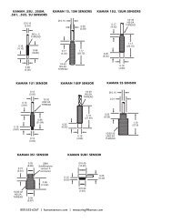
Sensors shown at 70%<br />
Note: All dimensions shown in inches (mm).<br />
KµDA 19-inch rack mount<br />
FEATURES AND BENEFITS<br />
■ Holds up to four dual-channel modules<br />
for a total of eight individual channels.<br />
■ Maximum of 12 analog outputs (three<br />
per module).<br />
■ RS-232 or RS-485 communication.<br />
■ Standard 19-inch Euro-rack includes<br />
power supply with built-in loss of<br />
power detection.<br />
4
KµDA SERIES<br />
SENSOR SPECIFICATIONS FOR NON-MAGNETIC TARGETS Characterized on aluminum<br />
Standard KµDA Sensor Type 2U 4U 9U 12U 16U 26U 38U 51U<br />
Offset<br />
inch 0.002 0.005 0.010 0.016 0.020 0.032 0.050 0.100<br />
(mm) (0.05) (0.125) (0.25) (0.4) (0.5) (0.8) (1.2) (1.5)<br />
Full scale output voltage for testing Volts dc 10 10 10 10 10 10 10 10<br />
Sensor thermal sensitivity shift<br />
with active temp. compensation<br />
Standard measuring range<br />
%/°C<br />
maximum<br />
±0.01 (standard range, 10 °C - 50 °C)<br />
inch 0.020 0.050 0.100 0.160 0.200 0.320 0.500 0.600<br />
(mm) (0.5) (1.25) (2.5) (4.0) (5.0) (8.0) (12) (15)<br />
Nonlinearity with 3 point typical 0.3 0.2 0.2 0.2 0.2 0.2 0.4 0.4<br />
calibration (+/-%FS) maximum 0.4 0.3 0.3 0.3 0.3 0.3 0.4 0.4<br />
Nonlinearity with 21 point typical 0.2 0.1 0.1 0.1 0.1 0.1 0.1 0.1<br />
calibration (+/-%FS) maximum 0.2 0.2 0.2 0.2 0.2 0.2 0.2 0.2<br />
Resolution 100 Hz mid scale typical 0.04 0.03<br />
(P-P %FS) 100 Hz full scale typical 0.08 0.08<br />
Resolution 1000 Hz mid scale typical 0.10 0.10<br />
(P-P %FS) 1000 Hz full scale typical 0.30 0.30<br />
Extended measuring range<br />
inch 0.030 0.070 0.150 0.240 0.320 0.500 0.800 1.000<br />
(mm) (0.75) (1.75) (3.75) (6.0) (8.0) (12.5) (20.25) (25.5)<br />
Nonlinearity with 3 point typical 0.8 0.7 0.7 0.7 0.7 0.7 0.7 0.7<br />
calibration (+/-%FS) maximum 1.0 1.0 1.0 1.0 1.0 1.0 1.0 1.0<br />
Nonlinearity with 21 point typical 0.3 0.2 0.2 0.2 0.2 0.2 0.2 0.2<br />
calibration (+/-%FS) maximum 0.4 0.3 0.3 0.3 0.3 0.3 0.3 0.3<br />
Resolution 100 Hz mid scale typical 0.04 0.03<br />
(P-P %FS) 100 Hz full scale typical 0.15 0.15<br />
Resolution 1000 Hz mid scale typical 0.10 0.10<br />
(P-P %FS) 1000 Hz full scale typical 0.30 0.30<br />
SENSOR SPECIFICATIONS FOR MAGNETIC TARGETS Characterized on 4130 steel<br />
Standard KµDA Sensor Type 2U** 4U** 9U** 12U** 16U 26U 38U 51U<br />
Offset<br />
inch 0.002 0.005 0.015 0.016 0.020 0.032 0.050 0.100<br />
(mm) (0.05) (0.125) (0.375) (0.4) (0.5) (0.8) (1.2) (1.5)<br />
Full scale output voltage for testing Volts dc ±10 ±10 10 10 10 10 10 10<br />
Sensor thermal sensitivity shift<br />
with active temp. compensation*<br />
Standard measuring range<br />
%/°C<br />
maximum<br />
±0.03 ±0.01 ±0.01<br />
inch 0.010 0.020 0.100 0.160 0.200 0.320 0.500 0.600<br />
(mm) (0.25) (0.50) (2.5) (4.0) (5.0) (8.0) (12) (15)<br />
Nonlinearity with 3 point typical 0.3 0.3 0.8 0.8 0.8 0.3 0.3 0.3<br />
calibration (+/-%FS) maximum 0.5 0.5 1.0 1.0 1.0 0.5 0.5 0.5<br />
Nonlinearity with 21 point typical 0.1 0.1 0.1 0.1 0.1 0.1 0.1 0.1<br />
calibration (+/-%FS) maximum 0.2 0.2 0.2 0.2 0.2 0.2 0.2 0.2<br />
Resolution 100 Hz mid scale typical 0.06 0.03<br />
(P-P %FS) 100 Hz full scale typical 0.12 0.09<br />
Resolution 1000 Hz mid scale typical 0.10 0.10<br />
(P-P %FS) 1000 Hz full scale typical 0.30 0.30<br />
Extended measuring range<br />
inch 0.015 0.025 0.150 0.240 0.320 0.500 0.800 1.000<br />
(mm) (0.375) (0.625) (3.75) (6.0) (8.0) (12.5) (20.25) (25.5)<br />
Nonlinearity with 3 point typical 0.8 0.8 0.8 0.8 0.8 0.8 0.8 0.8<br />
calibration (+/-%FS) maximum 1.0 1.0 1.0 1.0 1.0 1.0 1.0 1.0<br />
Nonlinearity with 21 point typical 0.2 0.2 0.2 0.2 0.2 0.2 0.2 0.2<br />
calibration (+/-%FS) maximum 0.3 0.3 0.3 0.3 0.3 0.3 0.3 0.3<br />
Resolution 100 Hz mid scale typical 0.06 0.04<br />
(P-P %FS) 100 Hz full scale typical 0.15 0.15<br />
Resolution 1000 Hz mid scale typical 0.10 0.10<br />
(P-P %FS) 1000 Hz full scale typical 0.30 0.30<br />
*Standard range, 25°C - 100°C.<br />
**Sensors not available with extension cable for steel.<br />
5
KµDA SERIES<br />
EXAMPLES OF CURRENT APPLICATIONS<br />
DRIVE SHAFT BALANCING<br />
GOAL<br />
■ Automate the QC testing of drive shafts on the<br />
balancing machine.<br />
■ Take <strong>data</strong> and derive TIR within two seconds.<br />
■ Must be integrated with existing PLC.<br />
SOLUTION<br />
A two-channel KµDA system was installed with the <strong>sensors</strong><br />
mounted to monitor each end of the rotating drive<br />
shaft. The PLC provided an output wired to one of the<br />
three digital inputs on KµDA which was configured to<br />
trigger two (one for each end of the drive shaft) of the<br />
KµDA programmable functions.<br />
KµDA performed these functions on each sensor:<br />
■ Captured two seconds worth of <strong>data</strong>.<br />
■ Derived the peak and valley values, then subtract them.<br />
■ Sent this value to one of the three analog outputs.<br />
■ Triggered one of the digital outputs if the analog value<br />
exceeded the acceptance specification.<br />
BENEFITS OF USING KµDA<br />
■ KµDA configurations are stored on board.<br />
■ KµDA takes on many of the tasks of PLC s.<br />
■ KµDA operates with all the benefits of digital circuitry,<br />
without a PC.<br />
■ With the use of a local enunciator wired to the KµDA<br />
digital output, the indication of pass or fail resided at<br />
the balancing with the technician.<br />
DISK THICKNESS IN READ/WRITE HEAD MANUFACTURING<br />
GOAL<br />
■ Implement a fast and accurate method to measure<br />
aluminum substrate thickness after lapping for sorting<br />
requirements.<br />
■ Must measure immediately after lapping. Discs will<br />
be wet and coated with residue. Cannot touch the disc.<br />
■ Must integrate with future process automation plans.<br />
SOLUTION<br />
A two-channel KµDA was integrated into a NEMA 4<br />
rated tabletop system, with the <strong>sensors</strong> mounted a fixed<br />
distance apart on opposite sides of the disc. Using a disc<br />
of known thickness, the spacing between the <strong>sensors</strong> is<br />
derived and stored in KµDA.<br />
The thickness of each disc placed in between the <strong>sensors</strong><br />
is calculated by subtracting the sum of the output of both<br />
<strong>sensors</strong> from the stored sensor spacing value. KµDA is<br />
configured to provide the thickness as an analog output,<br />
which is displayed locally to the operator in engineering<br />
units.<br />
BENEFITS OF USING KµDA<br />
■ KµDA configurations are stored on board. Once the<br />
configuration is set, KµDA operates without a PC.<br />
■ Performance can be verified as often as needed by<br />
checking the thickness of the known disc.<br />
■ KµDA is based on eddy current technology, so lapping<br />
residue, water, dirt, and grime are invisible.<br />
■ With built in digital I/O and RS-232/485, KµDA is<br />
ideal as a standalone system or easily integrated into<br />
any future automation process control platforms.<br />
6
KµDA SERIES<br />
EXAMPLES OF CURRENT APPLICATIONS<br />
ROLL GAP CONTROL AND WEB THICKNESS<br />
GOAL<br />
n Measure/display the gap at each end of a roller pair.<br />
n Provide local digital display for technicians making<br />
routine adjustments to the roll gap.<br />
n Provide for implementation of a plant-wide <strong>data</strong><br />
acquisition system to monitor system performance.<br />
SOLUTION<br />
A two-channel KµDA is integrated into a NEMA 4 rated<br />
enclosure with digital displays. A sensor is mounted to a<br />
lower roller bearing block and an aluminum target, to an<br />
upper block. With a known gap between the rollers, the<br />
sensor output is adjusted. Each sensor provides an analog<br />
voltage output proportional to the gap. KµDA calculates<br />
the difference between the sensor outputs and provides<br />
the difference between the gaps at each end of the<br />
roller. A limit output is triggered when this value exceeds<br />
a prescribed threshold, indicating a need for maintenance.<br />
BENEFITS OF USING KµDA<br />
n KµDA configurations are stored on board. Once the<br />
configuration is set, KµDA operates without a PC.<br />
n KµDA is an eddy current system and unaffected by<br />
n<br />
the cleanliness of the material being measured.<br />
RS-485 drop allows future integration into SPC/PM<br />
systems.<br />
PLASTIC INJECTION M<strong>OLD</strong>ING WALL THICKNESS<br />
GOAL<br />
n Monitor core movement in-situ during the injection<br />
molding process.<br />
n Integrate into a plant-wide <strong>data</strong> acquisition and<br />
control system.<br />
n Survive the high temperature and pressure of the<br />
mold environment.<br />
SOLUTION<br />
<strong>Kaman</strong> designed a custom sensor to meet the pressure<br />
(20,000 psi) and temperature (500° F) requirements. This<br />
sensor is characterized with KµDA electronics and<br />
embedded into the wall of the mold used for making<br />
medical waste buckets with stringent wall thickness specifications.<br />
The sensor face forms part of the mold wall<br />
and senses any movement of the core. The system alarms<br />
if movement is detected that exceeds the specified limit,<br />
triggering the material handler to discard any out-of-spec<br />
bucket. Via RS-232/485 interface, the <strong>data</strong> from each part<br />
is captured by the plant wide <strong>data</strong> acquisition system.<br />
BENEFITS OF USING KµDA<br />
n KµDA configurations can be stored and loaded as<br />
required by the plant wide <strong>data</strong> acquisition and control<br />
program. This allows an individual sensor to<br />
remain with the mold. When mold change is required<br />
to run different parts, the sensor in the new mold is<br />
attached to the KµDA and the control program loads<br />
the configuration for that sensor. All configuration<br />
n<br />
n<br />
<strong>data</strong>, calibration parameters, alarms, and functions are<br />
downloaded.<br />
KµDA is an eddy current system and unaffected by<br />
the presence of plastic in either liquid or solid form.<br />
Active temperature compensation allows for accurate<br />
readings regardless of the variation in temperature of<br />
the mold.<br />
7
KµDA SERIES<br />
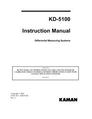
SPECIFICATIONS<br />
Operating temperature range:<br />
Sensors (4U through 51U): -55°C to +200°C.<br />
Sensor (2U): -55°C to +105°C.<br />
Electronics: -20°C to +50°C.<br />
Storage temperature range:<br />
Sensors (4U through 51U): -55°C to +200°C.<br />
Sensor (2U): -55°C to +105°C.<br />
Electronics: -55°C to +105°C.<br />
Power supply: +5 VDC, ±12 VDC.<br />
Cable length: 2m standard with optional 3m<br />
extension.<br />
RS-232<br />
(9 PIN FEMALE)<br />
POWER CONNECTOR<br />
(5 POSITION<br />
CIRCULAR DIN)<br />
ACCEPTS 3/16"<br />
MAX DIA SCREW<br />
KAMAN<br />
Instrumentation<br />
Keys Off Error Power<br />
(7.52)<br />
(7.03)<br />
Calibrate<br />
Measure<br />
Set Minimum<br />
User Function 1<br />
Set Mid Point<br />
User Function 2<br />
Set Maximum<br />
User Function 3<br />
Min<br />
Sensor<br />
1<br />
Min<br />
Sensor<br />
2<br />
Max<br />
Select/Zero<br />
Max<br />
Select/Zero<br />
KµDA<br />
(2.32)<br />
RX232<br />
GND<br />
486-<br />
GND<br />
GND<br />
GND<br />
GND<br />
GND<br />
GND<br />
D3 OUT<br />
3&4 RET<br />
D4 OUT<br />
D2 IN<br />
GND<br />
-12V<br />
GND<br />
(2.00)<br />
TX232<br />
232/486<br />
486+<br />
V1 OUT<br />
V2 OUT<br />
V3 OUT<br />
I1 OUT<br />
I2 OUT<br />
I3 OUT<br />
D1 OUT<br />
1&2 RET<br />
D2 OUT<br />
D1 IN<br />
D3 IN<br />
+12V<br />
+5V<br />
SENSOR 1 SENSOR 2<br />
All dimensions in inches.<br />
(.085)<br />
SENSOR 1<br />
(SMA CONNECTOR)<br />
All dimensions in inches.<br />
(4.64)<br />
SENSOR 2<br />
(SMA CONNECTOR)<br />
© Copyright 2000 <strong>Kaman</strong> Aerospace Corp. All specifications are subject to change without notice.<br />
KµDA is a registered trademark of <strong>Kaman</strong> Aerospace Corp.<br />
Printed in USA<br />
<strong>Kaman</strong> <strong>Precision</strong> Products | Measuring<br />
Voice: 719/635-6979 Fax: 719/634-8093<br />
e-mail: measuring@kaman.com<br />
www.kaman<strong>sensors</strong>.com<br />
8