DigiVIT User Manual - Kaman Precision | Position sensors
DigiVIT User Manual - Kaman Precision | Position sensors
DigiVIT User Manual - Kaman Precision | Position sensors

You also want an ePaper? Increase the reach of your titles
YUMPU automatically turns print PDFs into web optimized ePapers that Google loves.
Non-contact Displacement MeasuringSystem <strong>User</strong>’s <strong>Manual</strong>Copyright © 2013PART NO: 860525-001Last Revised: 9/16//2013<strong>Kaman</strong> <strong>Precision</strong> ProductsA Division of <strong>Kaman</strong> Aerospace Corporation217 Smith StreetMiddletown, CT 06457www.kaman<strong>sensors</strong>.com
TABLE OF CONTENTSPART 1 – INTRODUCTION..........................................................................................................4PART 2 – CONNECTIONS...........................................................................................................5PART 3 - FRONT PANEL CONTROLS .......................................................................................6PART 4 – MENU TREE ................................................................................................................74.2 mA Out Setup ....................................................................................................................84.3 Cal Setup ...........................................................................................................................84.4 Linearization Options .........................................................................................................84.4.1 2 Pt. Cal ......................................................................................................................84.4.2 6 Pt. Poly Cal ..............................................................................................................94.4.3 21 Pt. Pcws Cal...........................................................................................................94.5 Temperature Compensation ..............................................................................................94.6 Display Setup...................................................................................................................104.6.1 Display Percent .........................................................................................................104.6.2 Display Voltage .........................................................................................................104.6.3 Display Current .........................................................................................................104.7 Advanced Setup................................................................................................................104.7.1 Digital Filter ...............................................................................................................104.7.2 Sample Rate .............................................................................................................114.7.3 Ethernet Setup ..........................................................................................................114.7.4 Keypad Lockout ........................................................................................................114.8 Adjust Output ....................................................................................................................114.8.1 Zero Output ................................................................................................................114.8.2 2 Pt. Adjust................................................................................................................114.8.3 Clear Zero .................................................................................................................124.8.4 3 Pt. Adjust................................................................................................................12PART 5 - ETHERNET OUTPUT .................................................................................................135.1 Default IP Address & Ports ..............................................................................................135.2 UDP Packet .....................................................................................................................135.3 Console Software.............................................................................................................14PART 6 - CALIBRATION EXAMPLES........................................................................................156.1 General Information .........................................................................................................156.2 Calibration Fixturing .........................................................................................................16www.kaman<strong>sensors</strong>.com PART NO: 860525-001Last Revised 9/16/2013- 2 -
6.3 2-Point Linear Calibration .................................................................................................166.4 6-Point Polynomial Calibration..........................................................................................176.5 21-Point Piecewise Calibration .........................................................................................186.6 2-Point Adjustment............................................................................................................196.7 3-Point Adjustment............................................................................................................196.8 Temperature Compensation (Electronics and Sensor) .....................................................20PART 7 – OTHER FEATURES...................................................................................................217.1 Limits & Relay ..................................................................................................................217.2 IO bit/AUTOZERO............................................................................................................21APPENDIX A: COMMAND LIST.................................................................................................22APPENDIX B: digiVIT STANDARD PROBE OPTIONS..............................................................24APPENDIX C: digiVIT TYPICAL SPECIFICATIONS .................................................................26APPENDIX D: CALIBRATION EXAMPLES VIA ETHERNET INTERFACE ...............................27APPENDIX E: DIMENSIONS......................................................................................................31APPENDIX F: SOFTWARE LICENSE AGREEMENT ................................................................32www.kaman<strong>sensors</strong>.com PART NO: 860525-001Last Revised 9/16/2013- 3 -
PART 1 – INTRODUCTIONThe <strong>Kaman</strong> digiVIT is a revolutionary inductive displacement measuring instrument. ThedigiVIT simplifies use of a variety of Eddy Current <strong>sensors</strong> for precision measurements of;displacement, position, vibration, run-out, etc, in typical and difficult applications. The digiVIT isuser configurable and adjustable.The digiVIT does not require any special factory setup to work with most inductive <strong>sensors</strong>. Itincorporates a self tuning mechanism that optimizes set up for a given sensor, cable length,conductive target material, and range. Using the front panel controls, the digiVIT can easily becalibrated, temperature compensated, and adjusted for a variety of voltage and current outputoptions.Getting Started1.1 Connect PowerA +24 VDC power supply capable of supplying 0.13A is required to power digiVIT. Connect thepower supply to the digiVIT terminal block pins 1 and 2 (reference Part 2 on connections).1.2 Connect the SensorThe sensor is connected to the SMA connector. On application of power, if no sensor isconnected or the digiVIT senses and open connection the message 'No Sensor' will appear onthe display. If, the sensor is defective or its resistance is too low, the message 'Bad Sensor' willbe displayed. If the unit was previously calibrated, the display may indicate a voltage, currentor percentage depending on how the display was configured. If voltage or current was notselected, the default display is percent of full scale.1.3 Calibrate the SensorIf factory calibration has not been performed, the sensor must be calibrated before it willfunction properly. Reference PART 6 on calibration examples.1.4 Connect the OutputsConnect either the analog voltage output, current output, or use the Ethernet port over a UDPinterface. For the analog voltage and current output, output ranges (i.e. 0-5V, +/-5V, 0-10V, +/-10V, 0-20mA, or 4-20mA) can be selected using the front panel menu.For fixturing of <strong>sensors</strong> and other application considerations, reference <strong>Kaman</strong>’s InductiveTechnology Handbook. A copy can be downloaded free of charge from <strong>Kaman</strong>’s website:www.kaman<strong>sensors</strong>.com.www.kaman<strong>sensors</strong>.com PART NO: 860525-001Last Revised 9/16/2013- 4 -
PART 2 – CONNECTIONSThe digiVIT I/O connections are all through a 10 pin removable terminal block. The <strong>DigiVIT</strong>sensor is connected through an SMA coaxial connector on the opposite side of the enclosure.An RJ45 Ethernet connection is provided for UDP/IP communication.Pin Name Function1 +24V+24V Input @ 0.13A(must accommodate power-on surge current up to 300mA)2 Gnd Ground3 Vout Voltage Output (0-5, +/-5, 0-10, +/-10)4 Gnd Ground5 Iout Curent Loop Output (0-20mA, 4-20mA)6 Gnd Ground7 NC No Connection8 IO IO Bit for special functions -- standard setup for Autozero when grounded.9 Relay Solid State Relay Connection10 Relay Solid State Relay ConnectionTable 1 Terminal Block Pin-Outwww.kaman<strong>sensors</strong>.com PART NO: 860525-001Last Revised 9/16/2013- 5 -
PART 3 - FRONT PANEL CONTROLSThe digiVIT can easily be set up using the front panel controls.121. Sensor connection (SMA)2. Digital display3. Scroll up pushbutton4. Scroll down pushbutton5. Escape pushbutton6. Enter pushbutton7. Ethernet connection (RJ45)8. I/O screw terminals345687Figure 1 Front Panel ControlsNote: Press the Escape pushbutton (#5 in the figure above) momentarily to return to theprevious menu tree branch. Press and hold the Escape pushbutton to return to the normal runmode.www.kaman<strong>sensors</strong>.com PART NO: 860525-001Last Revised 9/16/2013- 6 -
PART 4 – MENU TREEThe menu tree for digiVIT, accessed by pushing either the Scroll Up or Scroll Down pushbuttonson the front panel, is shown below. The Scroll Up and Scroll Down pushbuttons will cyclethrough the options in a particular branch. To access a submenu simply scroll up or down in themain menu until the desired submenu is displayed, then push the Enter pushbutton. To leave asubmenu, momentarily push the Escape pushbutton. To return to the normal run mode,depress and hold the Escape pushbutton.Volt OutSetupmA OutSetupCalSetupDisplaySetupAdvancedSetupAdjustOutputReturn toRunZeroOutput2 PTAdjustClearZero3 PTAdjustDigitalFilterSampleRateEthernetSetupKeypadLockoutRelayLimitsRelayPolarityRelay HiLimitRelay LoLimitRelayHysteresisIPAddressUDP PortWriterUDP PortReaderMacAddress5000SPS10000SPSDisplayPercentDisplayVoltageDisplayCurrentLinearizeOutputTemp CmpSensorTemp CmpElectronics2 PTLin Cal6 PTPoly Cal21 PTPcws Cal4-20mACurrent0-20mACurrent0-10VOutput+/-10VOutput0-5VOutput+/-5VOutputFigure 2 Menu Treewww.kaman<strong>sensors</strong>.com PART NO: 860525-001Last Revised 9/16/2013- 7 -
4.1 Volt Out SetupThis option allows selection of the voltage output range from the system.The actual voltage will go 1% above or below the voltage output range selected if the sensor isabove or below the calibrated range.4.2 mA Out SetupThis option allows selection of the current output range from the system.The actual current will go 5% above or below the current output range selected if the sensor isabove or below the calibrated range. In the case of 0-20mA output, it will not go below zero.4.3 Cal SetupThis selection allows linearization calibration and temperature compensation. With theexception of the 2 Pt. or 3 Pt. Adjust (reference 4.8) all other calibration methods will zero outthe temperature compensation coefficients and any offset.4.4 Linearization Options3 options are available for linearization calibration, 2 point, 6 point and 21 point.Note: Performing a linearization calibration after a temperature compensation calibration willvoid the temperature compensation calibration. All linearization calibrations begin by locatingthe sensor at the maximum distance it will be from the target during operation. This is typicallythe sum of the offset distance and full scale range.4.4.1 2 Pt. CalThe 2 point calibration is useful if either linearity of the output is not a concern or if the sensor isoperated over a very short range. Ranges less than 10% of the standard range (a standardrange is normally 33% of the sensor diameter) typically will result in good linearity. For rangesbelow 5% of the standard range; this is the recommended method.To perform a 2 Pt calibration, the sensor needs to be position at MAX distance from the sensorface (i.e. full scale) so that it can optimize for a given sensor. After that, the sensor needs to bepositioned at only the offset (MIN) and full range (MAX) positions.Note: Any previous temperature compensation calibration will be voided when a 2 Pt. calibrationis performed.www.kaman<strong>sensors</strong>.com PART NO: 860525-001Last Revised 9/16/2013- 8 -
4.4.2 6 Pt. Poly CalThe 6 point polynomial cal fits a 5th order polynomial through the data points to linearize thesensor output. In most cases this method works very well though there can be exceptions.The sensor needs to be position at MAX distance from the sensor face (i.e. full scale) so that itcan optimize for a given sensor. After that the sensor needs to be position at offset (MIN) andthen at 20%, 40%, 60%, 80%, and 100% of the range to complete the calibration.Note: Any previous temperature compensation calibration will be voided when a 6 Pt. calibrationis performed.4.4.3 21 Pt. Pcws CalThis calibration will result in the best performance. It is a 21 point piecewise linearizationmethod. This option works best if the curve is too oddly shaped for a polynomial to fit well.The sensor needs to be positioned at the MAX distance from the sensor face (i.e. full scale) sothat it can optimize for a given sensor. After that, it needs to be positioned in 5% of the rangeincrements from 0-100%.Note: Any previous temperature compensation calibration will be voided when a 21 Pt.calibration is performed.4.5 Temperature CompensationThe digiVIT optimizes the sensor for temperature stability and linearity using proprietaryalgorithms. However, even with this optimization, some residual error exists due totemperature. Temperature stability can generally be improved by a factor of 5-10 usingadditional steps to temperature compensate the unit. To perform temperature compensation,data from 2 different displacements with 2 different temperatures must be acquired by the unit.The actual displacement does not matter, but the recommended displacements areaproximately10% and 90% of the calibrated range. If the best temperature coefficient is desiredat a particular displacement, that displacement should be chosen as one of the displacementsused. The temperature compensation algorithm will have the smallest temperature error at thatdisplacement 1 and 2 when the calibration is completed. The 4 required points are:D1T1 (Displacement 1, Temperature 1)D1T2 (Displacement 1, Temperature 2)D2T1 (Displacement 2, Temperature 1)D2T2 (Displacement 2, Temperature 2)The temperature compensation calibration menu controls the order of the 4 points.www.kaman<strong>sensors</strong>.com PART NO: 860525-001Last Revised 9/16/2013- 9 -
When temperature compensation is selected, the display shows a temperature relative to whenthe calibration process started. It is displayed in degrees Celsius, but is not particularlyaccurate in terms of absolute temperature.The first step is to go to D1T1, it does not matter if it is at the 10% or 90% point (or any point)and it does not matter what order you take the two temperature points in (rising or fallingtemperature). At this displacement, change the temperature of the sensor noting the output onthe display. It is best to avoid transients so by heating (or cooling) the sensor it is best to waituntil any transients have passed to take the data point. The unit does not care what the actualtemperatures used for the calibration are and they do not have to be the same for bothdisplacements. One method is to heat the sensor up some number of degrees, take one datapoint after any transients have passed, and take the second data point after it has cooled downsome. After the two temperature points have been collected at displacement 1, then positionthe sensor at displacement 2 and take two temperature points again.If changing the temperature resulted in slight offset and gain errors due to actual positionchanges, a 2 or 3 point adjustment calibration can be performed (see section 4.8.2 or 4.8.4).Temperature coefficients are not affected by a 2 point or 3 point adjustment calibration.4.6 Display SetupThe display has several different output options:4.6.1 Display PercentDisplays the percentage of the calibrated range where the sensor is positioned. Over and underrange will show greater than 100% and less than 0% but the voltage outputs will be constrainedto -1% to +101%. Current outputs are constrained to -5% to +105% (but will not go below0mA).4.6.2 Display VoltageDisplays the selected voltage output.4.6.3 Display CurrentDisplays the selected current output.4.7 Advanced Setup4.7.1 Digital FilterThe display is always filtered but the analog outputs (voltage and current) are not. Resolution ofthese outputs can be increased using a digital filter. The time constant options (tau) will varywww.kaman<strong>sensors</strong>.com PART NO: 860525-001Last Revised 9/16/2013- 10 -
slightly depending on the sample rate selected. If the time constant is 0.0 then no filter is usedand only the analog filter and the sample rate matter. The time constant displayed isrepresentative of how fast the system will respond to a step function. For example, a timeconstant of 0.8ms will get to 95% of the step within 3 time constants or 2.4ms.4.7.2 Sample RateThe sample rate of the system can be changed from 5,000 to 10,000 samples per second.5,000 samples per second are adequate for most applications and is the default. 10,000samples per second can be selected for special applications when required. At 10,000 samplesper second, communication with the system over the Ethernet port could slow substantially asthe processor is busy most of the time servicing the analog outputs. If analog output only isrequired, slower Ethernet communications should not be an issue.4.7.3 Ethernet SetupThe Ethernet setup allows change of the IP Address and the UDP reader and writer ports forconnection to the unit.4.7.4 Keypad LockoutTo prevent unauthorized access, the keypad can be disabled. When the keypad is locked outnone of the buttons on the front panel are active. To reactive the keypad press and hold thediamond and up arrow buttons until the menu reappears.4.8 Adjust Output4.8.1 Zero OutputThis will set the displayed output of the system to zero. If a unipolar voltage output is selected(0-5 or 0-10), output will be set to zero when the button is pressed. If a bipolar voltage output isselected it will reference to 50% (zero for the bipolar output voltage) when the button is pressed.This does not reset the range, so if a range with a unipolar output at 25% is zeroed, the displaymay lose 25% of the output range. You can also zero the output by grounding the IO bit on theterminal block.4.8.2 2 Pt. AdjustThe 2 point adjust makes a slight adjustment to an existing calibration. It allows for correction ofinstallation or slight loading errors in gain and offset. For this calibration the sensor must bepositioned at MIN and MAX with data taken at each point. This adjustment does not optimizethe output further; it simply corrects scale and offset errors. Temperature coefficients are notchanged. It will remove any offset from zeroing the sensor output.www.kaman<strong>sensors</strong>.com PART NO: 860525-001Last Revised 9/16/2013- 11 -
4.8.3 Clear ZeroThis will clear the zero offset and return to the calibrated absolute output.4.8.4 3 Pt. AdjustThe 3 point adjust makes a slight adjustment to an existing calibration. It allows for correction ofinstallation or slight loading errors in gain and offset. For this calibration, the sensor must bepositioned at MIN, MID, and MAX with data taken at each point. This adjustment does notoptimize the output further; it simply corrects scale, offset, and small linearity errors.Temperature coefficients are not changed. It will remove any offset from zeroing the sensoroutput. This option is used when more accuracy, but not a full calibration is required.www.kaman<strong>sensors</strong>.com PART NO: 860525-001Last Revised 9/16/2013- 12 -
PART 5 - ETHERNET OUTPUTThe digiVIT has an Ethernet output that communicates via a UDP/IP protocol. To protect thepacket it is required that any command is preceded by a sequence number and has a checksumat the end. It has a fixed IP address (which can be changed) and utilizes fixed ports (these canalso be changed) for sending and receiving data.5.1 Default IP Address & PortsDefault IP Address: 192.168.0.145Default UDP Writer Port: 55555Default UDP Reader Port: 555565.2 UDP PacketThe packet sent over the UDP port must be preceded by a sequence number and followed by achecksum. This is necessary because UDP does not guarantee arrival of the packet to thehost. The format of the packet is:$s#CCWhere the $ is the command preface and s is a sequence character from ASCII 'a' to 'z'. Whenthe digiVIT receives a command, it will respond with the same sequence number sent as thefirst character of the string. It is up to the host to determine if the packet arrived in sequenceand to take any action.The checksum is the last two characters and is preceded by the # sign indicating the checksumcharacters follow as the payload length is variable. It is the inverted 8 bit sum of the ASCIIvalues in the payload including the sequence number.www.kaman<strong>sensors</strong>.com PART NO: 860525-001Last Revised 9/16/2013- 13 -
5.3 Console SoftwareConsole software that lets the user enter UDP commands directly is available from <strong>Kaman</strong>’swebsite: www.kaman<strong>sensors</strong>.com. Examples for LabWindows and Labview programs are alsoavailable. Other software that allows more extensive features is also available from <strong>Kaman</strong>.Contact a <strong>Kaman</strong> representative for more information.The console connects directly to a PC Ethernet port (typically the second Ethernet wirelessconnection may have to be disabled as it may attempt to use it). It can also be connected to ahub or switch or the PC wireless port if configured. It is a simple way of executing the UDPcommands.Figure 3 Command Console Software Examplewww.kaman<strong>sensors</strong>.com PART NO: 860525-001Last Revised 9/16/2013- 14 -
PART 6 - CALIBRATION EXAMPLES6.1 General InformationThere are some rules of thumb when using the digiVIT:1) The standard range is 1/3 the diameter of the sensor against a non-ferrous target, suchas aluminum.2) The offset (closest point to sensor face) should be set at 10% of the standard sensorrange.3) The range against non-magnetic targets can typically be extended to 150% of thestandard range with reduced linearity and thermal sensitivity.4) Magnetic targets will have a range about 20% of the diameter of the sensor butperformance can vary significantly depending on the material and it's processing.5) Larger sensor diameters (>35mm) are not as affected by the target material as smallerdiameter <strong>sensors</strong> and will typically work better with the magnetic targets.6) When using magnetic targets that are moving laterally to the sensor face (i.e. rotatingtargets) the temperature compensation option should not be used (regardless of sensordiameter). This is due to a 'generator effect' caused by fluctuations in permeability overthe surface of the target influencing the temperature measurement of the sensor.7) For most ranges, the 6 point calibration will typically yield good to very good results whilethe 21 point calibration will give excellent results.8) When the calibrated range is less than 10% of the standard range a 2 point calibrationwill usually yield good results. At ranges less than 5% of the standard range, a 2 pointcalibration is recommended.9) All calibrations can be performed through the front panel or via a UDP command overthe Ethernet interface.10) For all calibrations, the front panel interface assumes a certain calibration order in thedata points. For calibrations via the UDP interface, data can be taken in any order withthe 'Done command' (C2, C6, CD, or CAM depending on the calibration type) issuedwhen the calibration is complete.11) Calibrations can be performed from MIN to MAX range or MAX to MIN range providedthe calibration steps precede sequentially.Calibration records for 2 point, 6 point, and 21 point calibrations can be downloaded from the<strong>Kaman</strong> website: www.kaman<strong>sensors</strong>.com.www.kaman<strong>sensors</strong>.com PART NO: 860525-001Last Revised 9/16/2013- 15 -
6.2 Calibration FixturingA good calibration starts with good calibration fixturing and reference. While in some cases thedigiVIT can be calibrated in-situ, it is typically calibrated using fixturing specially made for thepurpose. Small ranges may require special measuring equipment such as laser interferometersfor the best accuracy. If adequate fixturing is not available, <strong>Kaman</strong> offers a calibration service.Figure 4 Typical Calibration FixtureRefer to Appendix B for typical offset and range of recommended <strong>sensors</strong>.6.3 2-Point Linear CalibrationNote: Any previous temperature compensation calibration will be voided when a 2 Pt. calibrationis performed.The 2 point calibration is the simplest calibration and assumes the inherent output from thesensor is linear. Over the first 10% of the range this is true in a general sense, however evenwith 5% of the range; non-linearity is typically on the order of 1% of the calibrated full scaleoutput (though that is a pretty small absolute number typically). Over the standard full rangelinearity could be as large as 16%.1) Set the sensor flush with the target and move the micrometer to the MIN (offset) position.Zero the micrometer.www.kaman<strong>sensors</strong>.com PART NO: 860525-001Last Revised 9/16/2013- 16 -
2) <strong>Position</strong> the micrometer at the desired MAX (full scale range + offset) position.3) Select 'Cal Setup -> Lineariz Output -> 2 Pt. Lin. Cal.'. The unit will prompt 'Goto MAX PrsEntr'. With the sensor at MAX press the button. The unit will prompt 'Scanning PlsWait' -- this can take approximately 20 seconds. The unit is optimizing the setup for theparticular sensor, range, and target. Wait for this to finish.4) The digiVIT will prompt 'Goto MIN Prs Entr'. <strong>Position</strong> the micrometer to the MIN (offset)position and press .5) The digiVIT will prompt 'Goto 100% Prs Entr'. <strong>Position</strong> the micrometer to the MAX positionand press .The calibration is now complete. If the output reads 100.00% (or close to it) the calibration isgood. If 'Cal Error' is displayed, the digiVIT did not acquire enough analog to digital convertercounts between readings and the calibration sequence must be repeated.6.4 6-Point Polynomial CalibrationNote: Any previous temperature compensation calibration will be voided when a 6 Pt. calibrationis performed.The 6 point calibration is a relatively simple calibration that generally yields excellent results. Itassumes the inherent output from the sensor will have a reasonable fit to a 5th order polynomial-- generally a good assumption over most ranges. It will result in typical non-linearity on theorder of 0.1% to 0.3%. Most of the procedure is the same as the 2 point calibration except withmore data points. This calibration assumes the range is divided into 5 equal intervals. Forexample: a 0.5mm range will be divided into 0.5/5 = 0.1mm intervals.1) Set the sensor flush with the target and move the micrometer to the MIN (offset) position.Zero the micrometer.2) <strong>Position</strong> the micrometer at the desired MAX (full scale range + offset) position.3) Select 'Cal Setup -> Lineariz Output -> 6 Pt. Poly Cal.'. The unit will prompt 'Goto MAX PrsEntr'. With the sensor at full scale press the button. The unit will prompt 'Scanning PlsWait' -- this can take approximately 20 seconds. The unit is optimizing the setup for theparticular sensor, range, and target. Wait for this to finish.4) The digiVIT will prompt 'Goto MIN Prs Entr'. Go to the MIN position and press .5) The digiVIT will prompt 'Goto 20% Prs Entr'. Go to the 20% (0.1mm in our example) positionand press .6) Repeat step 5 for 40%, 60%, and 80% positions7) The digiVIT will prompt 'Goto 100% Prs Entr'. <strong>Position</strong> the micrometer to the MAX positionand press .www.kaman<strong>sensors</strong>.com PART NO: 860525-001Last Revised 9/16/2013- 17 -
The calibration is now complete. If the output reads 100.00% (or close to it) the calibration isgood. If 'Cal Error' is displayed, the digiVIT did not acquire enough analog to digital convertercounts between readings and the calibration sequence must be repeated.6.5 21-Point Piecewise CalibrationNote: Any previous temperature compensation calibration will be voided when a 21 Pt.calibration is performed.The 21 point calibration requires more displacement positions but is the most flexible and willcalibrate to almost any curve as long as it is monotonic and there is enough output betweensensor data points. If the fixturing is accurate it almost always yields excellent results. Thiscalibration assumes nothing about the sensor output as it is a piecewise table lookup approach.It will result in typical non-linearity on the order of 0.1%. Most of the procedure is the same asthe 6 point calibration except with more data points. This procedure assumes the range isdivided into 20 equal intervals. For example: a 0.5mm range is divided into 0.5/20 = 0.025mmintervals.1) Set the sensor flush with the target and move the micrometer to the MIN (offset) position.Zero the micrometer.2) <strong>Position</strong> the sensor at the desired MAX (full scale range + offset) position.3) Select 'Cal Setup -> Lineariz Output -> 21 Pt. Pcws Cal.'. The unit will prompt to 'Goto MAXPrs Entr'. With the sensor at full scale press the button. The unit will prompt 'ScanningPls Wait' -- this can take approximately 20 seconds. The unit is optimizing the setup for theparticular sensor, range, and target. Wait for this to finish.4) The digiVIT will prompt 'Goto MIN Prs Entr'. Go to the MIN position and press .5) The digiVIT will prompt 'Goto 5% Prs Entr'. Go to the 5% (0.025mm in our example) positionand press .7) Repeat step 5 for 10-95% positions.5) The digiVIT will prompt 'Goto 100% Prs Entr'. <strong>Position</strong> the micrometer to the MAX positionand press .The calibration is now complete. If the output reads 100.00% (or close to it) the calibration isgood. If 'Cal Error' displayed, the digiVIT did not acquire enough analog to digital convertercounts between readings and the calibration sequence must be repeated.www.kaman<strong>sensors</strong>.com PART NO: 860525-001Last Revised 9/16/2013- 18 -
6.6 2-Point AdjustmentNote: A 2 point adjustment does not void linearization or temperature compensationcalibrations.This procedure adjusts the calibration curve slightly for variations due to offset differences andslight target or loading differences. It is only for minor adjustments as it assumes the outputcurve has been affected linearly by environment differences.1) Select 'Adjust Output -> 2 pt. Adjust' and press .2) <strong>Position</strong> the sensor at the MIN (offset) position and press .3) <strong>Position</strong> the sensor at the MAX (full range + offset) position and press .The adjustment is now complete. If the output reads 100.00% (or close to it) the adjustment isgood. If 'Cal Error' is displayed, the adjustment is not good, a full recalibration may be required.6.7 3-Point AdjustmentNote: A 3 point adjustment does not void linearization or temperature compensationcalibrations.This procedure adjusts the calibration curve slightly for variations due to offset differences andslight target or loading differences. It is only for minor adjustments as it assumes the outputcurve has been affected linearly by environment differences.1) Select 'Adjust Output -> 3 pt. Adjust' and press .2) <strong>Position</strong> the sensor at the MIN (offset) position and press .3) <strong>Position</strong> the sensor at the MID (mid range or 50%) position and press .4) <strong>Position</strong> the sensor at the MAX (full range + offset) position and press .The adjustment is now complete. If the output reads 100.00% (or close to it) the adjustment isgood. If 'Cal Error' is displayed, the adjustment is not good, a full recalibration may be required.www.kaman<strong>sensors</strong>.com PART NO: 860525-001Last Revised 9/16/2013- 19 -
6.8 Temperature Compensation (Electronics and Sensor)While the digiVIT optimizes the sensor output for inherent temperature stability it can beimproved further by temperature compensation. The temperature of the sensor is measuredand used to compensate the output based on equations in the digiVIT. Optionally theElectronics can also be temperature compensated separately from the <strong>sensors</strong> and uses a builtin temperature sensor for the compensation. In either case the compensation method is thesame. These equations are set by collecting data at 4 temperature points:D1T1 -- Displacement 1, Temperature 1D1T2 -- Displacement 1, Temperature 2D2T1 -- Displacement 2, Temperature 1D2T2 -- Displacement 2, Temperature 2The digiVIT assumes that D1 is the same physical position for both T1 and T2. It does notassume that the temperature of D2T1 is the same as D1T1.As with any calibration temperature compensation depends on good fixturing. To some degreeif the fixturing is moving in temperature (due to material coefficient of thermal expansion – CTE)the same way it does in the application the digiVIT will tend to compensate for it. In many casesthe digiVIT can be temperature compensated in-situ.It is best to choose points D1 and D2 at 10% and 90% of the range (D1 could be 90% and D2could be 10% -- does not matter). If the expected usage is in a narrower range, better resultscould be obtained in the important displacement band by calibrating over the narrower range.1) Select 'Cal Setup -> Temp Cmp Sensor' from the front panel. The prompt will read'GotoD1T1 relC 0’. At this point it expects to be at Displacement 1 Temperature 1 in a fixture. Agood method is to fixture it at 90% of displacement (approximately -- it does not matterprecisely) and the heat the sensor head (if cable is going to be in the hot environment it shouldalso be included). You will see the relC x indicator rise as temperature increases and fall as itdecreases. It works best to heat it up and then let it cool down just a bit before taking the firstdata point so that transient effects are not included. Typically if the sensor is heated until the relC reads 10 or 12 or more that is sufficient. Let it cool down slightly to say 11 or even 9 andpress .2) The prompt will read 'GotoD1T2 relC 8'. Let it cool down until it is close to where it startedthough it is not necessary to let it cool down all the way. Then press the button.3) The prompt will read 'GotoD2T1 relC 1'. Reposition the sensor in the fixturing to be at asecond displacement. Typically 10% of the range is good setting. Again it is best to heat it up,let the transient go away and press the button at a rel C of 10 or 12. After the transienthas gone away, press the button.4) The prompt will read 'GotoD2T2 relC 9'. After the temperature goes down to near 1 or 2press the button and the temperature compensation is complete.www.kaman<strong>sensors</strong>.com PART NO: 860525-001Last Revised 9/16/2013- 20 -
CommandSystemPasslevelRequiredParameters Returns CommentsRXR NONE NONE Revision Read Firmware RevisionU NONE Sets Passlevel Passlevel 0-2Unlocks for higher level controlU KAMAN -- unlocks to <strong>User</strong> LevelU -- sets password to normal levelMISC TIMERWC NONE NONE Seconds Watch Clock (seconds since power on)WT NONE NONE Ticks Watch Ticks (Ticks since power on)CALIBRATIONCS NONE NONE -- Saves the calibration and all parametersCF NONE NONE FrequencySet Optimal Full Scale – Sets Frequency andOptimal Coil Current – sensor must be positionedat max displacement from sensor. This is the firstthing done in a calibration.CZ NONE NONE --Sets Zero and sets gains and offsets (Executedafter CF) – sensor must be positioned at theminimum displacement from sensor. This is thesecond thing done in a calibrationCP x NONE X = 0-20 AD ReadingCal Point (0-20) for piecewise linearization –sensor must be positioned at the correct percent offull scale – i.e. 0=0%, 1=5%,2 =10% … 20=100% -- direction (min to max or max to min) does notmatter as long as it changes monotonically. For 6point polynomial cals only use 0-5 points and theymust be spaced 20% apart ... i.e. pt 0 is 20%, pt1is 40% ... pt 5 = 100% of range. For a 2 point calpt 0 = 0% pt 1 = 100%.CD NONE NONE StatusCompletes the 21 point calibration and sets up thetables for operationC6 NONE NONE Status Completes the 6 point polynomial calC2 NONE NONE Status Completes the 2 point linear calCAZ NONE NONE -- Cal Adjust zero pointCAM NONE NONE -- Cal Adjust mid pointCAF NONE NONE -- Cal Adjust full scale pointCAD NONE NONE Status Complete 2 Point AdjustCT 0 NONE NONE -- Collect Temp Comp Data for D1T1CT 1 NONE NONE -- Collect Temp Comp Data for D1T2CT 2 NONE NONE -- Collect Temp Comp Data for D2T1CT 3 NONE NONE -- Collect Temp Comp Data for D2T2CT 4 NONE NONE Status Completes Temperature Compensation for SensorCT 5 NONE NONE StatusCompletes Temperature Compensation forElectronicswww.kaman<strong>sensors</strong>.com PART NO: 860525-001Last Revised 9/16/2013- 23 -
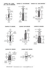
APPENDIX B: digiVIT STANDARD PROBE OPTIONSAlthough the digiVIT will work with nearly any sensor and any conductive target, the following <strong>sensors</strong>have been characterized over standard ranges with an aluminum target.www.kaman<strong>sensors</strong>.com PART NO: 860525-001Last Revised 9/16/2013- 24 -
Characterized with an aluminum target 2U 4U 9U 12U 16U 26U 38U 51UOffset inch 0.002 0.005 0.010 0.016 0.020 0.032 0.050 0.100(mm) (0.05) (0.13) (0.25) (0.40) (0.50) (.80) (1.20) (2.50)Short Range inch 0.010 0.025 0.050 0.080 0.100 0.160 0.250 0.300(mm) (0.25) (0.60) (1.25) (2.00) (2.50) (4.00) (6.00) (7.5)Standard Range inch 0.020 0.050 0.100 0.160 0.200 0.320 0.500 0.600(mm) ('0.50) (1.30) (2.50) (4.00) (5.00) (8.00) (12.0) (15.0)Extended Range inch 0.030 0.070 0.150 0.240 0.320 0.500 0.800 1.000(mm) (0.75) (1.75) (3.75) (6.00) (8.00) (12.5) (20.0) (25.0)Typical Specifications for stardard range, aluminum target, standard cable lengthNonlinearity 6 pt calibration ±%FS
APPENDIX C: digiVIT TYPICAL SPECIFICATIONSSpecifications below are typical but are sensor and target dependent. Some magnetic targetsmay not work well with the digiVIT.Parameter Specification NotesPower Supply +18-28V Current will change with inputInput Current 0.13A At +24V input typicalVoltage Output 0-5V,+/-5V,0-10V,+/-10VVoltage and current are simultaneouslyoutput, Outputs will over/under range by 1%Current OutputRangeOffsetResolution0-20mA, 4-20mA33% of sensor diameterstandard10% of range1/3000 RMS at fullbandwidth no filteringRanges can vary typically from 5% of thestandard range to 150% of standard rangeon non-magnetic targets. Magnetic targetsare highly variable.TypicalResolution Static 1/100000 RMS TypicalLinearity 6 pt. Cal 0.3% of Full Range Least Squares over standard range typicalLinearity 21 pt. Cal 0.1% of Full Range Least Squares over standard range typicalTargetsTemp Co w/o temp compAny conductive0.1%FR/ o CSome magnetic targets may not work well oronly over a substantially reduced rangeStandard range/AL target Typical sensorhead only -- no cableTempCo w/Temp comp 0.02%FR/ o C Standard range/AL targetElectronics TempCoElectronics Temp Range0.05-0.1%/ o C0-50 o CStandard range/AL target TypicalW/Electronics Temp Comp 5x typicalimprovementSensor DC Resistance 0.5 to 20 ohms 20 is 'no sensor'Sensor Inductance10uH to 50uHIt has been tested with <strong>sensors</strong> in this range.It may work with <strong>sensors</strong> up to 10mH inspecial situations not guaranteed.Specifications Subject to Change without Noticewww.kaman<strong>sensors</strong>.com PART NO: 860525-001Last Revised 9/16/2013- 26 -
APPENDIX D: CALIBRATION EXAMPLES VIA ETHERNET INTERFACECalibrations using the Ethernet interface have the same procedure as the examples in Part 6 ofthe manual. Data is entered using UDP commands from a PC instead of front panel controls.To perform these procedures, the digiVIT must be connected by an Ethernet cable to a PCrunning console software. Reference PART 5 of this manual.Refer to Appendix B for typical offset and range of recommended <strong>sensors</strong>.D.1 - 2 Point Linear Calibration1) Set the sensor flush with the target and move the micrometer to the MIN (offset) position.Zero the micrometer.2) <strong>Position</strong> the micrometer at the desired MAX (full scale range + offset) position.3) With the sensor at full scale, type UDP command ‘CF’. The unit will prompt 'Scanning PlsWait' -- this can take approximately 20 seconds. The unit is optimizing the setup for theparticular sensor, range, and target. Wait for this to finish.4) <strong>Position</strong> the micrometer to the MIN position (offset). Type ‘CZ’, then ‘CP 0’ to take data.5) <strong>Position</strong> the micrometer to the MAX position. Type ‘CP 2’ to take data, then ‘C2’ tocomplete the calibration.The calibration is now complete. If the calibration is good, the digiVIT will return a status of 0. Astatus of 1 is returned on a bad calibration and the calibration must be performed again.D.2 - 6 Point Polynomial CalibrationMost of the procedure is the same as the 2 point calibration except with more data points. Thiscalibration assumes the range is divided into 5 equal intervals. For example: a 0.5mm rangewill be divided into 0.5/5 = 0.1mm intervals.1) Set the sensor flush with the target and move the micrometer to the MIN (offset) position.Zero the micrometer.2) <strong>Position</strong> the micrometer at the desired MAX (full scale range + offset) position.3) With the sensor at full scale, type UDP command ‘CF’. The unit will prompt 'Scanning PlsWait' -- this can take approximately 20 seconds. The unit is optimizing the setup for theparticular sensor, range, and target. Wait for this to finish.4) <strong>Position</strong> the micrometer to the MIN position. Type ‘CZ’, then ‘CP 0’ to take data.5) Go to the 20% position (0.1mm in our example). Type ‘CP 1’ to take data.www.kaman<strong>sensors</strong>.com PART NO: 860525-001Last Revised 9/16/2013- 27 -
6) Repeat step 5 for 40%, 60%, and 80% positions. Type 'CP 2', 'CP 3', 'CP 4' at thesepositions respectively.7) <strong>Position</strong> the micrometer to the MAX position. Type ‘CP 6’ to take data, then ‘C6’ tocomplete the 6 point calibration.The calibration is now complete. If the calibration is good, the digiVIT will return a status of 0. Astatus of 1 is returned on a bad calibration and the calibration must be performed again.D.3 - 21 Point Piecewise CalibrationMost of the procedure is the same as the 6 point calibration except with more data points. Thisprocedure assumes the range is divided into 20 equal intervals. For example: a 0.5mm range isdivided into 0.5/20 = 0.025mm intervals.1) Set the sensor flush with the target and move the micrometer to the MIN (offset) position.Zero the micrometer.2) <strong>Position</strong> the micrometer at the desired MAX (full scale range + offset).3) With the sensor at full scale, type UDP command ‘CF’. The unit will prompt 'Scanning PlsWait' -- this can take approximately 20 seconds. The unit is optimizing the setup for theparticular sensor, range, and target. Wait for this to finish.4) <strong>Position</strong> the micrometer to the MIN (offset) position. Type ‘CZ’, then ‘CP 0’ to take data.5) Go to the 5% (0.025mm in our example) position. Type ‘CP 1’ to take data.6) Repeat step 5 for 10-95% positions. Type 'CP 2', 'CP 3', 'CP 4' … ‘CP19’ at these positionsrespectively.7) <strong>Position</strong> the micrometer to the MAX position. Type ‘CP 20’ to take data, then ‘CD’ tocomplete the 21 point calibration.The calibration is now complete. If the calibration is good, the digiVIT will return a status of 0. Astatus of 1 is returned on a bad calibration and the calibration must be performed again.www.kaman<strong>sensors</strong>.com PART NO: 860525-001Last Revised 9/16/2013- 28 -
D.4 - 2 Point Adjustment1) <strong>Position</strong> the sensor at the MIN (offset) position and type ‘CAZ’.2) <strong>Position</strong> the sensor at the MAX (full range + offset) position and type ‘CAF’ to take data, then‘CAD’ to complete the adjustment.The adjustment is now complete. If the calibration is good, the digiVIT will return a status of 0.A status of 1 is returned on a bad adjustment. If the adjustment is not good, a full recalibrationmay be required.D.5 - 3 Point Adjustment1) <strong>Position</strong> the sensor at the MIN (offset) position and type ‘CAZ’.2) <strong>Position</strong> the sensor at the MID (mid range or 50%) position and type ‘CAM’3) <strong>Position</strong> the sensor at the MAX (full range + offset) position and type ‘CAF’ to take data, then‘CAD’ to complete the adjustment.The adjustment is now complete. If the calibration is good, the digiVIT will return a status of 0.A status of 1 is returned on a bad adjustment. If the adjustment is not good, a full recalibrationmay be required.D.6 - Temperature Compensation (Electronics and Sensor)While the digiVIT optimizes the sensor output for inherent temperature stability it can beimproved further by temperature compensation. The temperature of the sensor is measuredand used to compensate the output based on equations in the digiVIT. Optionally theElectronics can also be temperature compensated separately from the <strong>sensors</strong> and uses a builtin temperature sensor for the compensation. In either case the compensation method is thesame. These equations are set by collecting data at 4 temperature points:D1T1 -- Displacement 1, Temperature 1D1T2 -- Displacement 1, Temperature 2D2T1 -- Displacement 2, Temperature 1D2T2 -- Displacement 2, Temperature 2The digiVIT assumes that D1 is the same physical position for both T1 and T2. It does notassume that the temperature of D2T1 is the same as D1T1.As with any calibration, temperature compensation depends on good fixturing. To some degreeif the fixturing is moving in temperature (due to material coefficient of thermal expansion – CTE)the same way it does in the application, the digiVIT will tend to compensate for it. In manycases the digiVIT can be temperature compensated in-situ.www.kaman<strong>sensors</strong>.com PART NO: 860525-001Last Revised 9/16/2013- 29 -
It is best to choose points D1 and D2 at 10% and 90% of the range (D1 could be 90% and D2could be 10% -- does not matter). If the expected usage is in a narrower range, better resultscould be obtained in the important displacement band by calibrating over the narrower range.1) Select 'Cal Setup -> Temp Cmp Sensor' from the front panel. The prompt will read'GotoD1T1 relC 0’. At this point it expects to be at Displacement 1 Temperature 1 in a fixture. Agood method is to fixture it at 90% of displacement (approximately -- it does not matterprecisely) and the heat the sensor head (if cable is going to be in the hot environment it shouldalso be included). You will see the relC x indicator rise as temperature increases and fall as itdecreases. It works best to heat it up and then let it cool down just a bit before taking the firstdata point so that transient effects are not included. Typically if the sensor is heated until the relC reads 10 or 12 or more that is sufficient. Let it cool down slightly to say 11 or even 9 and type‘CT 0’.2) The prompt will read 'GotoD1T2 relC 8'. Let it cool down until it is close to where it startedthough it is not necessary to let it cool down all the way. Then type ‘CT 1’.3) The prompt will read 'GotoD2T1 relC 1'. Reposition the sensor in the fixturing to be at asecond displacement. Typically 10% of the range is good setting. Again it is best to heat it up,let the transient go away and press the enter button at a rel C of 10 or 12. After the transienthas gone away, type ‘CT 2’.4) The prompt will read 'GotoD2T2 relC 9'. After the temperature goes down to near 1or 2 press type ‘CT 3’. Type ‘CT 4’ to complete this procedure if the compensation is for thesensor. Or, type ‘CT 5’ to complete this procedure if the compensation is for the electronics.A 0 is returned on a good and a 1 is returned on a bad temperature compensation. A fullrecalibration may be required on a bad calibration.www.kaman<strong>sensors</strong>.com PART NO: 860525-001Last Revised 9/16/2013- 30 -
APPENDIX E: DIMENSIONSDimensions in inches (mm).<strong>DigiVIT</strong> can be either DIN rail mounted or screw mounted with the mounting tabs (included).<strong>DigiVIT</strong> with Mounting tabswww.kaman<strong>sensors</strong>.com PART NO: 860525-001Last Revised 9/16/2013- 31 -
APPENDIX F: SOFTWARE LICENSE AGREEMENTPLEASE READ CAREFULLY - DO NOT DISCARDTHIS IS A LEGAL AGREEMENT.BY USING THIS SOFTWARE YOU ACCEPT THIS LICENSE AGREEMENT ANDWARRANTY ANDYOU AGREE TO THESE TERMS AND CONDITIONS.LICENSE. This is a license agreement between you and <strong>Kaman</strong> <strong>Precision</strong> Products("<strong>Kaman</strong>"). <strong>Kaman</strong> grants you the non-exclusive right to use the enclosed <strong>Kaman</strong> softwareprogram ("SOFTWARE") on any computer and there is no restriction on the number ofcomputers the software can be installed on.COPYRIGHT AND BACKUP. The SOFTWARE is owned by <strong>Kaman</strong> or its suppliers and isprotected by United States copyright laws and international treaty provisions. You may make asmany copies of the SOFTWARE for backup or archival purposes as desired, as long as thecopyright and proprietary notices in this license are included in the copy. You may not reverseengineer, decompile, disassemble, or create derivative works from the software.TERMINATION OF LICENSE. You may terminate this license by destroying theSOFTWARE together with any backup copy. This license will also terminate if you fail tocomply with any term or condition of this Agreement. You agree upon such termination todestroy the SOFTWARE together with any backup copy of the SOFTWARE.LIMITED WARRANTY. <strong>Kaman</strong> does not warrant that the SOFTWARE will meet yourrequirements, that operation of the SOFTWARE will be uninterrupted or error-free, or that allSOFTWARE errors will be corrected. <strong>Kaman</strong> is not responsible for problems caused bychanges in the operating characteristics of computer hardware or computer operating systemswhich are made after the release of the SOFTWARE nor for problems in the interaction of theSOFTWARE with non-<strong>Kaman</strong> software. <strong>Kaman</strong> will have no responsibility to replace or refundthe license fee of media damaged by accident, abuse, or misapplication.THE ABOVE WARRANTIES ARE EXCLUSIVE AND IN LIEU OF ALL OTHER WARRANTIES,EXPRESS OR IMPLIED, INCLUDING WARRANTIES OF MERCHANTABILITY, FITNESS FORA PARTICULAR PURPOSE AND NON-INFRINGEMENT. NO ORAL OR WRITTENINFORMATION OR ADVICE GIVEN BY EDI, ITS EMPLOYEES, DISTRIBUTORS, ORAGENTS SHALL INCREASE THE SCOPE OF THE ABOVE WARRANTIES OR CREATE ANYNEW WARRANTIES. SOME STATES DO NOT ALLOW THE EXCLUSION OF IMPLIEDWARRANTIES, SO THE ABOVE EXCLUSION MAY NOT APPLY TO YOU. IN THAT EVENT,ANY IMPLIED WARRANTIES ARE LIMITED IN DURATION TO THIRTY (30) DAYS FROMTHE DATE OF SHIPMENT OF THE SOFTWARE.LIMITATION OF REMEDIES. IN NO EVENT WILL KAMAN BE LIABLE TO YOU FOR ANYSPECIAL, CONSEQUENTIAL, INDIRECT OR SIMILAR DAMAGES, INCLUDING ANY LOSTPROFITS OR LOST DATA ARISING OUT OF THE USE OR INABILITY TO USE THEwww.kaman<strong>sensors</strong>.com PART NO: 860525-001Last Revised 9/16/2013- 32 -
SOFTWARE OR ANY DATA SUPPLIED THEREWITH EVEN IF KAMAN OR ANYONE ELSEHAS BEEN ADVISED OF THE POSSIBILITY OF SUCH DAMAGES OR FOR ANY CLAIM BYANY OTHER PARTY. IN NO CASE SHALL KAMAN'S LIABILITY EXCEED THE PURCHASEPRICE FOR THE SOFTWARE.GOVERNMENT LICENSEE. If you are acquiring the SOFTWARE on behalf of any unit oragency of the United States Government, the following provisions apply: The Governmentacknowledges KAMAN's representation that the SOFTWARE and its documentation weredeveloped at private expense and no part thereof is in the public domain.The Government acknowledges <strong>Kaman</strong>’s representation that the SOFTWARE is "RestrictedComputer Software" as that term is defined in Clause 52.227-19 of the Federal AcquisitionRegulations (FAR) and is "Commercial Computer Software" as that term is defined inSubpart 227.471 of the Department of Defense Federal Acquisition Supplement (DFARS). TheGovernment agrees that: (i) if the SOFTWARE is supplied to the Department of Defense(DOD), the SOFTWARE is classified as "Commercial Computer Software" and the Governmentis acquiring only "restricted rights" in the SOFTWARE and its documentation as that term isdefined in Clause 252.227-7013(c)(1) of the DFARS and (ii) if the SOFTWARE is supplied toany unit or agency of the United States Government other than DOD, the Government's rights inthe SOFTWARE and its documentation will be as defined in Clause 52.227-19(c)(2) of the FAR.EXPORT LAW ASSURANCES. You acknowledge and agree that the SOFTWARE issubject to restrictions and controls imposed by the United States Export Administration Act (the"Act") and the regulations hereunder. You agree and certify that neither the SOFTWARE norany direct product thereof is being or will be acquired, shipped, transferred or re-exported,directly or indirectly, into any country prohibited by the Act and the regulations hereunder or willbe used for any purposes prohibited by the same.GENERAL. This agreement will be governed by the laws of the State of Connecticut. Shouldyou have any questions concerning this agreement, or if you desire to contact <strong>Kaman</strong> for anyreason, please write: <strong>Kaman</strong> <strong>Precision</strong> Products, 217 Smith Street, Middletown, CT 06457.www.kaman<strong>sensors</strong>.com PART NO: 860525-001Last Revised 9/16/2013- 33 -