Non-contact Displacement Measuring System User's Manual
Non-contact Displacement Measuring System User's Manual
Non-contact Displacement Measuring System User's Manual

Create successful ePaper yourself
Turn your PDF publications into a flip-book with our unique Google optimized e-Paper software.
<strong>Non</strong>-<strong>contact</strong> <strong>Displacement</strong> <strong>Measuring</strong><br />
<strong>System</strong> User’s <strong>Manual</strong><br />
Copyright © 2013<br />
PART NO: 860525-001<br />
Last Revised: 8/23/2013<br />
Kaman Precision Products<br />
A Division of Kaman Aerospace Corporation<br />
217 Smith Street<br />
Middletown, CT 06457<br />
www.kamansensors.com
TABLE OF CONTENTS<br />
PART 1 – INTRODUCTION..........................................................................................................4<br />
PART 2 – CONNECTIONS...........................................................................................................5<br />
PART 3 - FRONT PANEL CONTROLS .......................................................................................6<br />
PART 4 – MENU TREE ................................................................................................................7<br />
4.2 mA Out Setup ....................................................................................................................8<br />
4.3 Cal Setup ...........................................................................................................................8<br />
4.4 Linearization Options .........................................................................................................8<br />
4.4.1 2 Pt. Cal ......................................................................................................................8<br />
4.4.2 6 Pt. Poly Cal ..............................................................................................................8<br />
4.4.3 21 Pt. Pcws Cal...........................................................................................................9<br />
4.5 Temperature Compensation ..............................................................................................9<br />
4.6 Display Setup...................................................................................................................10<br />
4.6.1 Display Percent .........................................................................................................10<br />
4.6.2 Display Voltage .........................................................................................................10<br />
4.6.3 Display Current .........................................................................................................10<br />
4.7 Advanced Setup................................................................................................................10<br />
4.7.1 Digital Filter ...............................................................................................................10<br />
4.7.2 Sample Rate .............................................................................................................10<br />
4.7.3 Ethernet Setup ..........................................................................................................11<br />
4.7.4 Keypad Lockout ........................................................................................................11<br />
4.8 Adjust Output ....................................................................................................................11<br />
4.8.1 Zero Output ................................................................................................................11<br />
4.8.2 2 Pt. Adjust................................................................................................................11<br />
4.8.3 Clear Zero .................................................................................................................11<br />
4.8.4 3 Pt. Adjust................................................................................................................12<br />
PART 5 - ETHERNET OUTPUT .................................................................................................13<br />
5.1 Default IP Address & Ports ..............................................................................................13<br />
5.2 UDP Packet .....................................................................................................................13<br />
5.3 Console Software.............................................................................................................14<br />
PART 6 - CALIBRATION EXAMPLES........................................................................................15<br />
6.1 General Information .........................................................................................................15<br />
6.2 Calibration Fixturing .........................................................................................................16<br />
www.kamansensors.com PART NO: 860525-001<br />
Last Revised 8/23/2013<br />
- 2 -
6.3 2-Point Linear Calibration .................................................................................................16<br />
6.4 6-Point Polynomial Calibration..........................................................................................17<br />
6.5 21-Point Piecewise Calibration .........................................................................................18<br />
6.6 2-Point Adjustment............................................................................................................18<br />
6.7 3-Point Adjustment............................................................................................................19<br />
6.8 Temperature Compensation (Electronics and Sensor) .....................................................19<br />
PART 7 – OTHER FEATURES...................................................................................................21<br />
7.1 Limits & Relay ..................................................................................................................21<br />
7.2 IO bit/AUTOZERO............................................................................................................21<br />
APPENDIX A: COMMAND LIST.................................................................................................22<br />
APPENDIX B: digiVIT STANDARD PROBE OPTIONS..............................................................24<br />
APPENDIX C: digiVIT TYPICAL SPECIFICATIONS .................................................................26<br />
APPENDIX D: CALIBRATION EXAMPLES VIA ETHERNET INTERFACE ...............................27<br />
APPENDIX E: DIMENSIONS......................................................................................................31<br />
APPENDIX F: SOFTWARE LICENSE AGREEMENT ................................................................32<br />
www.kamansensors.com PART NO: 860525-001<br />
Last Revised 8/23/2013<br />
- 3 -
PART 1 – INTRODUCTION<br />
The Kaman digiVIT is a revolutionary inductive displacement measuring instrument. The<br />
digiVIT simplifies use of a variety of Eddy Current sensors for precision measurements of;<br />
displacement, position, vibration, run-out, etc, in typical and difficult applications. The digiVIT is<br />
user configurable and adjustable.<br />
The digiVIT does not require any special factory setup to work with most inductive sensors. It<br />
incorporates a self tuning mechanism that optimizes set up for a given sensor, cable length,<br />
conductive target material, and range. Using the front panel controls, the digiVIT can easily be<br />
calibrated, temperature compensated, and adjusted for a variety of voltage and current output<br />
options.<br />
Getting Started<br />
1.1 Connect Power<br />
A +24 VDC power supply capable of supplying 0.13A is required to power digiVIT. Connect the<br />
power supply to the digiVIT terminal block pins 1 and 2 (reference Part 2 on connections).<br />
1.2 Connect the Sensor<br />
The sensor is connected to the SMA connector. On application of power, if no sensor is<br />
connected or the digiVIT senses and open connection the message 'No Sensor' will appear on<br />
the display. If, the sensor is defective or its resistance is too low, the message 'Bad Sensor' will<br />
be displayed. Normally the digiVIT displays a percentage which is an indication of the<br />
calibrated range, assuming a factory calibration has been performed.<br />
1.3 Calibrate the Sensor<br />
If factory calibration has not been performed, the sensor must be calibrated before it will<br />
function properly. Reference PART 6 on calibration examples.<br />
1.4 Connect the Outputs<br />
Connect either the analog voltage outputs, current outputs, or use the Ethernet port over a UDP<br />
interface. For the analog voltage or current outputs, output ranges (i.e. 0-5V, +/-5V, 0-10V, +/-<br />
10V, 0-20mA, or 4-20mA) can be selected using the front panel menu.<br />
For fixturing of sensors and other application considerations, reference Kaman’s Inductive<br />
Technology Handbook. A copy can be downloaded free of charge from Kaman’s website:<br />
www.kamansensors.com.<br />
www.kamansensors.com PART NO: 860525-001<br />
Last Revised 8/23/2013<br />
- 4 -
PART 2 – CONNECTIONS<br />
The digiVIT I/O connections are all through a 10 pin removable terminal block. The DigiVIT<br />
sensor is connected through an SMA coaxial connector on the opposite side of the enclosure.<br />
Pin Name Function<br />
1 +24V<br />
+24V Input @ 0.13A<br />
(must accommodate power-on surge current up to 300mA)<br />
2 Gnd Ground<br />
3 Vout Voltage Output (0-5, +/-5, 0-10, +/-10)<br />
4 Gnd Ground<br />
5 Iout Curent Loop Output (0-20mA, 4-20mA)<br />
6 Gnd Ground<br />
7 NC No Connection<br />
8 IO IO Bit for special functions -- standard setup for Autozero when grounded.<br />
9 Relay Solid State Relay Connection<br />
10 Relay Solid State Relay Connection<br />
Table 1 Terminal Block Pin-Out<br />
www.kamansensors.com PART NO: 860525-001<br />
Last Revised 8/23/2013<br />
- 5 -
PART 3 - FRONT PANEL CONTROLS<br />
The digiVIT can easily be set up using the front panel controls.<br />
Figure 1 Front Panel Controls<br />
Note: Press and hold the diamond Key (#5 on the figure above) to retune to the Main Menu.<br />
www.kamansensors.com PART NO: 860525-001<br />
Last Revised 8/23/2013<br />
- 6 -
PART 4 – MENU TREE<br />
The menu tree for digiVIT front panel controls is shown below. The up and down arrows will<br />
cycle through the options in a particular branch. If for example, 0-10V output was selected, that<br />
would be the first item shown in the Volt out Setup.<br />
Figure 2 Menu Tree<br />
www.kamansensors.com PART NO: 860525-001<br />
Last Revised 8/23/2013<br />
- 7 -
4.1 Volt Out Setup<br />
This option allows selection of the voltage output range from the system.<br />
The actual voltage will go 1% above or below the voltage output range selected if the sensor is<br />
above or below the calibrated range.<br />
4.2 mA Out Setup<br />
This option allows selection of the current output range from the system.<br />
The actual current will go 5% above or below the current output range selected if the sensor is<br />
above or below the calibrated range. In the case of 0-20mA output, it will not go below zero.<br />
4.3 Cal Setup<br />
This selection allows linearization calibration and temperature compensation. With the<br />
exception of the 2 Pt. or 3 Pt. Adjust (reference 4.8) all other calibration methods will zero out<br />
the temperature compensation coefficients and any offset.<br />
4.4 Linearization Options<br />
4.4.1 2 Pt. Cal<br />
The 2 point calibration is useful if either linearity of the output is not a concern or if the sensor is<br />
operated over a very short range. Ranges less than 10% of the standard range (33% of the<br />
sensor diameter) typically will result in good linearity. For ranges below 5% of the standard<br />
range; this is the recommended method.<br />
To perform a 2 Pt calibration, the sensor needs to be position at MAX distance from the sensor<br />
face (i.e. full scale) so that it can optimize for a given sensor. After that, the sensor needs to be<br />
positioned at only the offset (MIN) and full range (MAX) positions.<br />
Any previous temperature compensation calibrations are void when a 2 Pt. calibration is<br />
performed.<br />
4.4.2 6 Pt. Poly Cal<br />
The 6 point polynomial cal fits a 5th order polynomial through the data points to linearize the<br />
sensor output. In most cases this method works very well though there can be exceptions.<br />
The sensor needs to be position at MAX distance from the sensor face (i.e. full scale) so that it<br />
can optimize for a given sensor. After that the sensor needs to be position at offset (MIN) and<br />
then at 20%, 40%, 60%, 80%, and 100% of the range to complete the calibration.<br />
www.kamansensors.com PART NO: 860525-001<br />
Last Revised 8/23/2013<br />
- 8 -
Any previous temperature compensation calibrations are void when a 6 Pt. calibration is<br />
performed.<br />
4.4.3 21 Pt. Pcws Cal<br />
This calibration will result in the best performance. It is a 21 point piecewise linearization<br />
method. This option works best if the curve is too oddly shaped for a polynomial to fit well.<br />
The sensor needs to be positioned at the MAX distance from the sensor face (i.e. full scale) so<br />
that it can optimize for a given sensor. After that, it needs to be positioned in 5% of the range<br />
increments from 0-100<br />
Any previous temperature compensation calibrations are void when a 21 Pt. calibration is<br />
performed.<br />
4.5 Temperature Compensation<br />
The digiVIT optimizes the sensor for temperature stability and linearity using proprietary<br />
algorithms. However, even with this optimization, some residual error exists due to<br />
temperature. Temperature stability can generally be improved by a factor of 5-10 using<br />
additional steps to temperature compensate the unit. To perform temperature compensation,<br />
data from 2 different displacements with 2 different temperatures must be acquired by the unit.<br />
The actual displacement does not matter, but typically works best if the displacements are<br />
approximately 10% and 90% of the calibrated range. If the best temperature coefficient is<br />
desired at a particular displacement, that displacement should be chosen as one of the<br />
displacements used. The temperature compensation algorithm will have the smallest<br />
temperature error at that displacement when the calibration is completed. The 4 required points<br />
are:<br />
in that order.<br />
D1T1 (<strong>Displacement</strong> 1, Temperature 1)<br />
D1T2 (<strong>Displacement</strong> 1, Temperature 2)<br />
D2T1 (<strong>Displacement</strong> 2, Temperature 1), and<br />
D2T2 (<strong>Displacement</strong> 2, Temperature 2)<br />
When temperature compensation is selected, the display shows a temperature relative to when<br />
the calibration process started. It is approximately in degrees Celsius, but is not particularly<br />
accurate in terms of absolute temperature.<br />
The first step is to go to D1T1, it does not matter if it is at the 10% or 90% point (or any point)<br />
and it does not matter what order you take the two temperature points in (rising or falling<br />
temperature). At this displacement change the temperature of the sensor noting the output on<br />
the display. It is best to avoid transients so by heating (or cooling) the sensor it is best to wait<br />
until after any transients have passed to take the data point. The unit does not care what the<br />
actual temperatures used for the calibration are and they do not have to be the same for both<br />
www.kamansensors.com PART NO: 860525-001<br />
Last Revised 8/23/2013<br />
- 9 -
displacements. One method is to heat the sensor up some number of degrees, take one data<br />
point after any transients have passed, and take the second data point after it has cooled down<br />
some. After the two temperature points have been collected at displacement 1, then position<br />
the sensor at displacement 2 and take two temperature points again.<br />
If changing the temperature resulted in slight offset and gain errors due to actual position<br />
changes, a 2 or 3 point adjustment calibration can be performed. Temperature coefficients are<br />
not affected.<br />
4.6 Display Setup<br />
The display has several different output options:<br />
4.6.1 Display Percent<br />
Displays the percentage of the calibrated range where the sensor is positioned. Over and under<br />
range will show greater than 100% and less than 0% but the voltage outputs will be constrained<br />
to -1% to +101%. Current outputs are constrained to -5% to +105% (but will not go below<br />
0mA).<br />
4.6.2 Display Voltage<br />
Displays the selected voltage output.<br />
4.6.3 Display Current<br />
Displays the selected current output.<br />
4.7 Advanced Setup<br />
4.7.1 Digital Filter<br />
The display is always filtered but the analog outputs (voltage and current) are not. Resolution of<br />
these outputs can be increased using a digital filter. The time constant options (tau) will vary<br />
slightly depending on the sample rate selected. If the time constant is 0.0 then no filter is used<br />
and only the analog filter and the sample rate matter. The time constant displayed is<br />
representative of how fast the system will respond to a step function. For example, a time<br />
constant of 0.8ms will get to 95% of the step within 3 time constants or 2.4ms.<br />
4.7.2 Sample Rate<br />
The sample rate of the system can be changed from 5,000 to 10,000 samples per second.<br />
5,000 samples per second are adequate for most applications and is the default. 10,000<br />
samples per second can be selected for special applications when required. At 10,000 samples<br />
www.kamansensors.com PART NO: 860525-001<br />
Last Revised 8/23/2013<br />
- 10 -
per second, communication with the system over the Ethernet port could slow substantially as<br />
the processor is busy most of the time servicing the analog outputs. If analog output only is<br />
required, slower Ethernet communications should not be an issue.<br />
4.7.3 Ethernet Setup<br />
The Ethernet setup allows change of the IP Address and the UDP reader and writer ports for<br />
connection to the unit.<br />
4.7.4 Keypad Lockout<br />
To prevent unauthorized access, the keypad can be disabled. When the keypad is locked out<br />
none of the buttons on the front panel are active. To reactive the keypad press and hold the<br />
diamond and up arrow buttons until the menu reappears.<br />
4.8 Adjust Output<br />
4.8.1 Zero Output<br />
This will set the displayed output of the system to zero. If a unipolar voltage output is selected<br />
(0-5 or 0-10), output will be set to zero when the button is pressed. If a bipolar voltage output is<br />
selected it will reference to 50% (zero for the bipolar output voltage) when the button is pressed.<br />
This does not reset the range, so if a range with a unipolar output at 25% is zeroed, the display<br />
may lose 25% of the output range. You can also zero the output by grounding the IO bit on the<br />
terminal block.<br />
4.8.2 2 Pt. Adjust<br />
The 2 point adjust makes a slight adjustment to an existing calibration. It allows for correction of<br />
installation or slight loading errors in gain and offset. For this calibration the sensor must be<br />
positioned at MIN and MAX with data taken at each point. This adjustment does not optimize<br />
the output further; it simply corrects scale and offset errors. Temperature coefficients are not<br />
changed. It will remove any offset from zeroing the sensor output.<br />
4.8.3 Clear Zero<br />
This will clear the zero offset and return to the calibrated absolute output.<br />
www.kamansensors.com PART NO: 860525-001<br />
Last Revised 8/23/2013<br />
- 11 -
4.8.4 3 Pt. Adjust<br />
The 3 point adjust makes a slight adjustment to an existing calibration. It allows for correction of<br />
installation or slight loading errors in gain and offset. For this calibration, the sensor must be<br />
positioned at MIN, MID, and MAX with data taken at each point. This adjustment does not<br />
optimize the output further; it simply corrects scale, offset, and small linearity errors.<br />
Temperature coefficients are not changed. It will remove any offset from zeroing the sensor<br />
output. This option is used when more accuracy, but not a full calibration is required.<br />
www.kamansensors.com PART NO: 860525-001<br />
Last Revised 8/23/2013<br />
- 12 -
PART 5 - ETHERNET OUTPUT<br />
The digiVIT has an Ethernet output that communicates via a UDP/IP protocol. To protect the<br />
packet it is required that any command is preceded by a sequence number and has a checksum<br />
at the end. It has a fixed IP address (which can be changed) and utilizes fixed ports (these can<br />
also be changed) for sending and receiving data.<br />
5.1 Default IP Address & Ports<br />
Default IP Address: 192.168.0.145<br />
Default UDP Writer Port: 55555<br />
Default UDP Reader Port: 55556<br />
5.2 UDP Packet<br />
The packet sent over the UDP port must be preceded by a sequence number and followed by a<br />
checksum. This is necessary because UDP does not guarantee arrival of the packet to the<br />
host. The format of the packet is:<br />
$s#CC<br />
Where the $ is the command preface and s is a sequence character from ASCII 'a' to 'z'. When<br />
the digiVIT receives a command, it will respond with the same sequence number sent as the<br />
first character of the string. It is up to the host to determine if the packet arrived in sequence<br />
and to take any action.<br />
The checksum is the last two characters and is preceded by the # sign indicating the checksum<br />
characters follow as the payload length is variable. It is the inverted 8 bit sum of the ASCII<br />
values in the payload including the sequence number.<br />
www.kamansensors.com PART NO: 860525-001<br />
Last Revised 8/23/2013<br />
- 13 -
5.3 Console Software<br />
Console software that lets the user enter UDP commands directly is available from Kaman’s<br />
website: www.kamansensors.com. Examples for LabWindows and Labview programs are also<br />
available. Other software that allows more extensive features is also available from Kaman.<br />
Contact a Kaman representative for more information.<br />
The console connects directly to a PC Ethernet port (typically the second Ethernet wireless<br />
connection may have to be disabled as it may attempt to use it). It can also be connected to a<br />
hub or switch or the PC wireless port if configured. It is a simple way of executing the UDP<br />
commands.<br />
Figure 3 Command Console Software Example<br />
www.kamansensors.com PART NO: 860525-001<br />
Last Revised 8/23/2013<br />
- 14 -
PART 6 - CALIBRATION EXAMPLES<br />
6.1 General Information<br />
There are some rules of thumb when using the digiVIT:<br />
1) The standard range is 1/3 the diameter of the sensor against a non-ferrous target, such<br />
as aluminum.<br />
2) The offset (closest point to sensor face) should be set at 10% of the standard sensor<br />
range.<br />
3) The range against non-magnetic targets can typically be extended to 150% of the<br />
standard range with reduced linearity and thermal sensitivity.<br />
4) Magnetic targets will have a range about 20% of the diameter of the sensor but<br />
performance can vary significantly depending on the material and it's processing.<br />
5) Larger sensor diameters (>35mm) are not as affected by the target material as smaller<br />
diameter sensors and will typically work better with the magnetic targets.<br />
6) When using magnetic targets that are moving laterally to the sensor face (i.e. rotating<br />
targets) the temperature compensation option should not be used (regardless of sensor<br />
diameter). This is due to a 'generator effect' caused by fluctuations in permeability over<br />
the surface of the target influencing the temperature measurement of the sensor.<br />
7) For most ranges, the 6 point calibration will typically yield good to very good results while<br />
the 21 point calibration will give excellent results.<br />
8) When the calibrated range is less than 10% of the standard range a 2 point calibration<br />
will usually yield good results. At ranges less than 5% of the standard range, a 2 point<br />
calibration is recommended.<br />
9) All calibrations can be performed through the front panel or via a UDP command over<br />
the Ethernet interface.<br />
10) For all calibrations, the front panel interface assumes a certain calibration order in the<br />
data points. For calibrations via the UDP interface, data can be taken in any order with<br />
the 'Done command' (C2, C6, CD, or CAM depending on the calibration type) issued<br />
when the calibration is complete.<br />
11) Calibrations can be performed from MIN to MAX range or MAX to MIN range provided<br />
the calibration steps precede sequentially.<br />
Calibration records for 2 point, 6 point, and 21 point calibrations can be downloaded from the<br />
Kaman website: www.kamansensors.com.<br />
www.kamansensors.com PART NO: 860525-001<br />
Last Revised 8/23/2013<br />
- 15 -
6.2 Calibration Fixturing<br />
A good calibration starts with good calibration fixturing and reference. While in some cases the<br />
digiVIT can be calibrated in-situ, it is typically calibrated using fixturing specially made for the<br />
purpose. Small ranges may require special measuring equipment such as laser interferometers<br />
for the best accuracy. If adequate fixturing is not available, Kaman offers a calibration service.<br />
Figure 4 Typical Calibration Fixture<br />
Refer to Appendix B for typical offset and range of recommended sensors.<br />
6.3 2-Point Linear Calibration<br />
The 2 point calibration is the simplest calibration and assumes the inherent output from the<br />
sensor is linear. Over the first 10% of the range this is true in a general sense, however even<br />
with 5% of the range; non-linearity is typically on the order of 1% of the calibrated full scale<br />
output (though that is a pretty small absolute number typically). Over the standard full range<br />
linearity could be as large as 16%.<br />
1) Set the sensor flush with the target and move the micrometer to the MIN (offset) position.<br />
Zero the micrometer.<br />
2) Position the micrometer at the desired MAX (full scale range + offset) position.<br />
www.kamansensors.com PART NO: 860525-001<br />
Last Revised 8/23/2013<br />
- 16 -
3) Select 'Cal Setup -> Lineariz Output -> 2 Pt. Lin. Cal.'. The unit will prompt 'Goto MAX Prs<br />
Entr'. With the sensor at MAX press the button. The unit will prompt 'Scanning Pls<br />
Wait' -- this can take approximately 20 seconds. The unit is optimizing the setup for the<br />
particular sensor, range, and target. Wait for this to finish.<br />
4) The digiVIT will prompt 'Goto MIN Prs Entr'. Position the micrometer to the MIN (offset)<br />
position and press .<br />
5) The digiVIT will prompt 'Goto 100% Prs Entr'. Position the micrometer to the MAX position<br />
and press .<br />
The calibration is now complete. If the output reads 100.00% (or close to it) the calibration is<br />
good. If 'Cal Error' is displayed, the digiVIT did not acquire enough analog to digital converter<br />
counts between readings and the calibration sequence must be repeated.<br />
6.4 6-Point Polynomial Calibration<br />
The 6 point calibration is a relatively simple calibration that generally yields excellent results. It<br />
assumes the inherent output from the sensor will have a reasonable fit to a 5th order polynomial<br />
-- generally a good assumption over most ranges. It will result in typical non-linearity on the<br />
order of 0.1% to 0.3%. Most of the procedure is the same as the 2 point calibration except with<br />
more data points. This calibration assumes the range is divided into 5 equal intervals. For<br />
example: a 0.5mm range will be divided into 0.5/5 = 0.1mm intervals.<br />
1) Set the sensor flush with the target and move the micrometer to the MIN (offset) position.<br />
Zero the micrometer.<br />
2) Position the micrometer at the desired MAX (full scale range + offset) position.<br />
3) Select 'Cal Setup -> Lineariz Output -> 6 Pt. Poly Cal.'. The unit will prompt 'Goto MAX Prs<br />
Entr'. With the sensor at full scale press the button. The unit will prompt 'Scanning Pls<br />
Wait' -- this can take approximately 20 seconds. The unit is optimizing the setup for the<br />
particular sensor, range, and target. Wait for this to finish.<br />
4) The digiVIT will prompt 'Goto MIN Prs Entr'. Go to the MIN position and press .<br />
5) The digiVIT will prompt 'Goto 20% Prs Entr'. Go to the 20% (0.1mm in our example) position<br />
and press .<br />
6) Repeat step 5 for 40%, 60%, and 80% positions<br />
7) The digiVIT will prompt 'Goto 100% Prs Entr'. Position the micrometer to the MAX position<br />
and press .<br />
The calibration is now complete. If the output reads 100.00% (or close to it) the calibration is<br />
good. If 'Cal Error' is displayed, the digiVIT did not acquire enough analog to digital converter<br />
counts between readings and the calibration sequence must be repeated.<br />
www.kamansensors.com PART NO: 860525-001<br />
Last Revised 8/23/2013<br />
- 17 -
6.5 21-Point Piecewise Calibration<br />
The 21 point calibration requires more displacement positions but is the most flexible and will<br />
calibrate to almost any curve as long as it is monotonic and there is enough output between<br />
sensor data points. If the fixturing is accurate it almost always yields excellent results. This<br />
calibration assumes nothing about the sensor output as it is a piecewise table lookup approach.<br />
It will result in typical non-linearity on the order of 0.1%. Most of the procedure is the same as<br />
the 6 point calibration except with more data points. This procedure assumes the range is<br />
divided into 20 equal intervals. For example: a 0.5mm range is divided into 0.5/20 = 0.025mm<br />
intervals.<br />
1) Set the sensor flush with the target and move the micrometer to the MIN (offset) position.<br />
Zero the micrometer.<br />
2) Position the sensor at the desired MAX (full scale range + offset) position.<br />
3) Select 'Cal Setup -> Lineariz Output -> 21 Pt. Pcws Cal.'. The unit will prompt to 'Goto MAX<br />
Prs Entr'. With the sensor at full scale press the button. The unit will prompt 'Scanning<br />
Pls Wait' -- this can take approximately 20 seconds. The unit is optimizing the setup for the<br />
particular sensor, range, and target. Wait for this to finish.<br />
4) The digiVIT will prompt 'Goto MIN Prs Entr'. Go to the MIN position and press .<br />
5) The digiVIT will prompt 'Goto 5% Prs Entr'. Go to the 5% (0.025mm in our example) position<br />
and press .<br />
7) Repeat step 5 for 10-95% positions.<br />
5) The digiVIT will prompt 'Goto 100% Prs Entr'. Position the micrometer to the MAX position<br />
and press .<br />
The calibration is now complete. If the output reads 100.00% (or close to it) the calibration is<br />
good. If 'Cal Error' displayed, the digiVIT did not acquire enough analog to digital converter<br />
counts between readings and the calibration sequence must be repeated.<br />
6.6 2-Point Adjustment<br />
This procedure adjusts the calibration curve slightly for variations due to offset differences and<br />
slight target or loading differences. It is only for minor adjustments as it assumes the output<br />
curve has been affected linearly by environment differences.<br />
1) Select 'Adjust Output -> 2 pt. Adjust' and press .<br />
2) Position the sensor at the MIN (offset) position and press .<br />
3) Position the sensor at the MAX (full range + offset) position and press .<br />
www.kamansensors.com PART NO: 860525-001<br />
Last Revised 8/23/2013<br />
- 18 -
The adjustment is now complete. If the output reads 100.00% (or close to it) the adjustment is<br />
good. If 'Cal Error' is displayed, the adjustment is not good, a full recalibration may be required.<br />
6.7 3-Point Adjustment<br />
This procedure adjusts the calibration curve slightly for variations due to offset differences and<br />
slight target or loading differences. It is only for minor adjustments as it assumes the output<br />
curve has been affected linearly by environment differences.<br />
1) Select 'Adjust Output -> 3 pt. Adjust' and press .<br />
2) Position the sensor at the MIN (offset) position and press .<br />
3) Position the sensor at the MID (mid range or 50%) position and press .<br />
4) Position the sensor at the MAX (full range + offset) position and press .<br />
The adjustment is now complete. If the output reads 100.00% (or close to it) the adjustment is<br />
good. If 'Cal Error' is displayed, the adjustment is not good, a full recalibration may be required.<br />
6.8 Temperature Compensation (Electronics and Sensor)<br />
While the digiVIT optimizes the sensor output for inherent temperature stability it can be<br />
improved further by temperature compensation. The temperature of the sensor is measured<br />
and used to compensate the output based on equations in the digiVIT. Optionally the<br />
Electronics can also be temperature compensated separately from the sensors and uses a built<br />
in temperature sensor for the compensation. In either case the compensation method is the<br />
same. These equations are set by collecting data at 4 temperature points:<br />
D1T1 -- <strong>Displacement</strong> 1, Temperature 1<br />
D1T2 -- <strong>Displacement</strong> 1, Temperature 2<br />
D2T1 -- <strong>Displacement</strong> 2, Temperature 1<br />
D2T2 -- <strong>Displacement</strong> 2, Temperature 2<br />
The digiVIT assumes that D1 is the same physical position for both T1 and T2. It does not<br />
assume that the temperature of D2T1 is the same as D1T1.<br />
As with any calibration temperature compensation depends on good fixturing. To some degree<br />
if the fixturing is moving in temperature (due to material coefficient of thermal expansion – CTE)<br />
the same way it does in the application the digiVIT will tend to compensate for it. In many cases<br />
the digiVIT can be temperature compensated in-situ.<br />
It is best to choose points D1 and D2 at 10% and 90% of the range (D1 could be 90% and D2<br />
could be 10% -- does not matter). If the expected usage is in a narrower range, better results<br />
could be obtained in the important displacement band by calibrating over the narrower range.<br />
www.kamansensors.com PART NO: 860525-001<br />
Last Revised 8/23/2013<br />
- 19 -
1) Select 'Cal Setup -> Temp Cmp Sensor' from the front panel. The prompt will read<br />
'GotoD1T1 relC 0’. At this point it expects to be at <strong>Displacement</strong> 1 Temperature 1 in a fixture. A<br />
good method is to fixture it at 90% of displacement (approximately -- it does not matter<br />
precisely) and the heat the sensor head (if cable is going to be in the hot environment it should<br />
also be included). You will see the relC x indicator rise as temperature increases and fall as it<br />
decreases. It works best to heat it up and then let it cool down just a bit before taking the first<br />
data point so that transient effects are not included. Typically if the sensor is heated until the rel<br />
C reads 10 or 12 or more that is sufficient. Let it cool down slightly to say 11 or even 9 and<br />
press .<br />
2) The prompt will read 'GotoD1T2 relC 8'. Let it cool down until it is close to where it started<br />
though it is not necessary to let it cool down all the way. Then press the button.<br />
3) The prompt will read 'GotoD2T1 relC 1'. Reposition the sensor in the fixturing to be at a<br />
second displacement. Typically 10% of the range is good setting. Again it is best to heat it up,<br />
let the transient go away and press the button at a rel C of 10 or 12. After the transient<br />
has gone away, press the button.<br />
4) The prompt will read 'GotoD2T2 relC 9'. After the temperature goes down to near 1 or 2<br />
press the button and the temperature compensation is complete.<br />
www.kamansensors.com PART NO: 860525-001<br />
Last Revised 8/23/2013<br />
- 20 -
PART 7 – OTHER FEATURES<br />
7.1 Limits & Relay<br />
The digiVIT contains a solid state relay connected to pins 9 and 10 of the terminal block. This<br />
relay has a 40 ohm closed impedance and is rated for 60V and 100mA. The relay is controlled<br />
by the limit settings and is set up as a window comparator. The hi and lo limits, polarity (NC or<br />
NO), and hysteresis are setup using the UDP commands. By default the relay will be on if the<br />
output is less than 10% or greater than 90% and off otherwise.<br />
To set the limits and relay, the digiVIT must be connected by an Ethernet cable to a PC running<br />
console software. Reference PART 5 of this manual.<br />
The output from the system is from 0 to 100,000 where 100,000 is 100%. The relay is setup the<br />
same way.<br />
For example, a command of SCLL 20000 sets the low limit to 20%.<br />
S(R)CLP x USER X = polarity Polarity SET(READ) Limit Polarity 0 = NO 1= NC<br />
S(R)CLH xxxx USER xx = Hi Limit Hi Limit SET(READ) Limit Hi (Signed Long Int)<br />
S(R)CLL xxxxx USER xx = Lo Limit Lo Limit SET(READ) Limit LO (Signed Long Int)<br />
S(R)CLD xxxx USER xx = Hysteresis Hysteresis SET(READ) Limit Deadband (Hysteresis)<br />
(Signed Long Int)<br />
Table 2 Relay Commands<br />
7.2 IO bit/AUTOZERO<br />
The IO bit (pin 8) is set up to have the same functionality as zeroing the system from the<br />
console or the front panel menu. The system will zero the output when pin 8 is grounded and<br />
will function normally when it is open. This means if the system is setup for bipolar voltages it<br />
will go to 50% when grounded and 0% for unipolar voltage settings.<br />
Note: this does not move the effective range of the system as it is only offsetting the output<br />
reading. If the sensor is physically at 5% of the range and is zeroed, the bipolar output setting<br />
the output will read 50% but then the linear range will then be 45% to 145%.<br />
www.kamansensors.com PART NO: 860525-001<br />
Last Revised 8/23/2013<br />
- 21 -
APPENDIX A: COMMAND LIST<br />
The following are the low level commands for the user to program an interface. Many of the<br />
setup commands are read or write. The command starts with an 'S' for a write (such as SCLL<br />
20000) or an 'R' for a read (RCLL will read back the setting). Settings are stored in non-volatile<br />
system memory.<br />
Command<br />
Monitor Commands<br />
Passlevel<br />
Required<br />
Parameters Returns Comments<br />
MD NONE NONE Distance Output Monitor Distance Output 100000=100%<br />
ML NONE NONE Monitor Limit Monitor Limit 0= in range 1=low 2 = hi<br />
MR NONE NONE Monitor Relay Monitor Relay 0= Open 1 = Closed<br />
AutoZero Function<br />
ZZ NONE NONE -- Zeroes the output<br />
ZC NONE NONE -- Clears the zero on the output<br />
Limit Setup<br />
S(R)CLP x USER X = polarity Polarity SET(READ) Limit Polarity 0 = NO 1= NC<br />
S(R)CLH xxxx USER xx = Hi Limit Hi Limit SET(READ) Limit Hi (Signed Long Int)<br />
S(R)CLL xxxxx USER xx = Lo Limit Lo Limit SET(READ) Limit LO (Signed Long Int)<br />
S(R)CLD xxxx USER xx = Hysteresis Hysteresis<br />
SET(READ) Limit Deadband (Hysteresis)<br />
(Signed Long Int)<br />
Ethernet Setup<br />
S(R)EA xxx xxx xxx xxx<br />
USER<br />
xx xxx xxx xxx =<br />
IP Address<br />
IP Address<br />
SET(READ) Ethernet IP Address<br />
Note: Separate Octets with spaces not '.'<br />
S(R)EW xxxxx USER xx = port UDP Writer Port SET(READ) Ethernet Writer Port<br />
S(R)ER xxxxx USER xx = port UDP Reader SET(READ) Ethernet Reader Port<br />
REM NONE MAC READ Ethernet MAC Address<br />
Output Setup<br />
S(R)UI x USER x = setting Setting<br />
S(R)UV x USER x = setting Setting<br />
SET(READ) User Current Output<br />
0=0-20mA<br />
1=4-20mA<br />
SET(READ) User Voltage output<br />
0=0-5V<br />
1 =+/-5V<br />
2=0-10V<br />
3=+/-10V<br />
www.kamansensors.com PART NO: 860525-001<br />
Last Revised 8/23/2013<br />
- 22 -
Command<br />
<strong>System</strong><br />
Passlevel<br />
Required<br />
Parameters Returns Comments<br />
RXR NONE NONE Revision Read Firmware Revision<br />
U NONE Sets Passlevel Passlevel 0-2<br />
Unlocks for higher level control<br />
U KAMAN -- unlocks to User Level<br />
U -- sets password to normal level<br />
MISC TIMER<br />
WC NONE NONE Seconds Watch Clock (seconds since power on)<br />
WT NONE NONE Ticks Watch Ticks (Ticks since power on)<br />
CALIBRATION<br />
CS NONE NONE -- Saves the calibration and all parameters<br />
CF NONE NONE Frequency<br />
Set Optimal Full Scale – Sets Frequency and<br />
Optimal Coil Current – sensor must be positioned<br />
at max displacement from sensor. This is the first<br />
thing done in a calibration.<br />
CZ NONE NONE --<br />
Sets Zero and sets gains and offsets (Executed<br />
after CF) – sensor must be positioned at the<br />
minimum displacement from sensor. This is the<br />
second thing done in a calibration<br />
CP x NONE X = 0-20 AD Reading<br />
Cal Point (0-20) for piecewise linearization –<br />
sensor must be positioned at the correct percent of<br />
full scale – i.e. 0=0%, 1=5%,2 =10% … 20=100% -<br />
- direction (min to max or max to min) does not<br />
matter as long as it changes monotonically. For 6<br />
point polynomial cals only use 0-5 points and they<br />
must be spaced 20% apart ... i.e. pt 0 is 20%, pt1<br />
is 40% ... pt 5 = 100% of range. For a 2 point cal<br />
pt 0 = 0% pt 1 = 100%.<br />
CD NONE NONE Status<br />
Completes the 21 point calibration and sets up the<br />
tables for operation<br />
C6 NONE NONE Status Completes the 6 point polynomial cal<br />
C2 NONE NONE Status Completes the 2 point linear cal<br />
CAZ NONE NONE -- Cal Adjust zero point<br />
CAM NONE NONE -- Cal Adjust mid point<br />
CAF NONE NONE -- Cal Adjust full scale point<br />
CAD NONE NONE Status Complete 2 Point Adjust<br />
CT 0 NONE NONE -- Collect Temp Comp Data for D1T1<br />
CT 1 NONE NONE -- Collect Temp Comp Data for D1T2<br />
CT 2 NONE NONE -- Collect Temp Comp Data for D2T1<br />
CT 3 NONE NONE -- Collect Temp Comp Data for D2T2<br />
CT 4 NONE NONE Status Completes Temperature Compensation for Sensor<br />
CT 5 NONE NONE Status<br />
Completes Temperature Compensation for<br />
Electronics<br />
www.kamansensors.com PART NO: 860525-001<br />
Last Revised 8/23/2013<br />
- 23 -
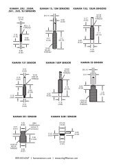
APPENDIX B: digiVIT STANDARD PROBE OPTIONS<br />
Although the digiVIT will work with nearly any sensor and any conductive target, the following sensors<br />
have been characterized over standard ranges with an aluminum target.<br />
www.kamansensors.com PART NO: 860525-001<br />
Last Revised 8/23/2013<br />
- 24 -
Characterized with an aluminum target 2U 4U 9U 12U 16U 26U 38U 51U<br />
Offset<br />
inch<br />
(mm)<br />
0.002<br />
(0.05)<br />
0.005<br />
(0.13)<br />
0.010<br />
0.25<br />
0.016<br />
(0.40)<br />
0.020<br />
(0.50)<br />
0.032<br />
(0.80)<br />
0.050<br />
(1.20)<br />
0.100<br />
(2.5)<br />
Short range<br />
Inch<br />
(mm)<br />
0.010<br />
(0.25)<br />
0.025<br />
(0.60)<br />
0.050<br />
(1.25)<br />
0.080<br />
(2.00)<br />
0.100<br />
(2.50)<br />
0.160<br />
(4.00)<br />
0.250<br />
(6.00)<br />
0.300<br />
(7.50)<br />
Standard range<br />
Inch<br />
(mm)<br />
0.020<br />
(0.50)<br />
0.050<br />
(1.30)<br />
0.100<br />
(2.50)<br />
0.160<br />
(4.00)<br />
0.200<br />
(5.00)<br />
0.320<br />
(8.00)<br />
0.500<br />
(12.00)<br />
0.600<br />
(15.00)<br />
Extended range<br />
Inch<br />
(mm)<br />
0.030<br />
(0.75)<br />
0.070<br />
(3.75)<br />
0.150<br />
(3.75)<br />
0.240<br />
(6.00)<br />
0.320<br />
(8.00)<br />
0.500<br />
(12.50)<br />
0.800<br />
(20.00)<br />
1.000<br />
(25.00)<br />
Typical specifications for standard range, aluminum target, standard cable length:<br />
<strong>Non</strong>linearity 6 pt calibration +/- %FS
APPENDIX C: digiVIT TYPICAL SPECIFICATIONS<br />
Specifications below are typical but are sensor and target dependent. Some magnetic targets<br />
may not work well with the digiVIT.<br />
Parameter Specification Notes<br />
Power Supply +18-28V Current will change with input<br />
Input Current 0.13A At +24V input typical<br />
Voltage Output 0-5V,+/-5V,0-10V,+/-10V<br />
Voltage and current are simultaneously<br />
output, Outputs will over/under range by 1%<br />
Current Output<br />
Range<br />
Offset<br />
Resolution<br />
0-20mA, 4-20mA<br />
33% of sensor diameter<br />
standard<br />
10% of range<br />
1/3000 RMS at full<br />
bandwidth no filtering<br />
Ranges can vary typically from 5% of the<br />
standard range to 150% of standard range<br />
on non-magnetic targets. Magnetic targets<br />
are highly variable.<br />
Typical<br />
Resolution Static 1/100000 RMS Typical<br />
Linearity 6 pt. Cal 0.3% of Full Range Least Squares over standard range typical<br />
Linearity 21 pt. Cal 0.1% of Full Range Least Squares over standard range typical<br />
Targets<br />
Temp Co w/o temp comp<br />
Any conductive<br />
0.1%FR/ o C<br />
Some magnetic targets may not work well or<br />
only over a substantially reduced range<br />
Standard range/AL target Typical sensor<br />
head only -- no cable<br />
TempCo w/Temp comp 0.02%FR/ o C Standard range/AL target<br />
Electronics TempCo<br />
Electronics Temp Range<br />
0.05-0.1%/ o C<br />
0-50 o C<br />
Standard range/AL target Typical<br />
W/Electronics Temp Comp 5x typical<br />
improvement<br />
Sensor DC Resistance 0.5 to 20 ohms 20 is 'no sensor'<br />
Sensor Inductance<br />
10uH to 50uH<br />
It has been tested with sensors in this range.<br />
It may work with sensors up to 10mH in<br />
special situations not guaranteed.<br />
Specifications Subject to Change without Notice<br />
www.kamansensors.com PART NO: 860525-001<br />
Last Revised 8/23/2013<br />
- 26 -
APPENDIX D: CALIBRATION EXAMPLES VIA ETHERNET INTERFACE<br />
Calibrations using the Ethernet interface have the same procedure as the examples in Part 6 of<br />
the manual. Data is entered using UDP commands from a PC instead of front panel controls.<br />
To perform these procedures, the digiVIT must be connected by an Ethernet cable to a PC<br />
running console software. Reference PART 5 of this manual.<br />
Refer to Appendix B for typical offset and range of recommended sensors.<br />
D.1 - 2 Point Linear Calibration<br />
1) Set the sensor flush with the target and move the micrometer to the MIN (offset) position.<br />
Zero the micrometer.<br />
2) Position the micrometer at the desired MAX (full scale range + offset) position.<br />
3) With the sensor at full scale, type UDP command ‘CF’. The unit will prompt 'Scanning Pls<br />
Wait' -- this can take approximately 20 seconds. The unit is optimizing the setup for the<br />
particular sensor, range, and target. Wait for this to finish.<br />
4) Position the micrometer to the MIN position (offset). Type ‘CZ’, then ‘CP 0’ to take data.<br />
5) Position the micrometer to the MAX position. Type ‘CP 2’ to take data, then ‘C2’ to<br />
complete the calibration.<br />
The calibration is now complete. If the calibration is good, the digiVIT will return a status of 0. A<br />
status of 1 is returned on a bad calibration and the calibration must be performed again.<br />
D.2 - 6 Point Polynomial Calibration<br />
Most of the procedure is the same as the 2 point calibration except with more data points. This<br />
calibration assumes the range is divided into 5 equal intervals. For example: a 0.5mm range<br />
will be divided into 0.5/5 = 0.1mm intervals.<br />
1) Set the sensor flush with the target and move the micrometer to the MIN (offset) position.<br />
Zero the micrometer.<br />
2) Position the micrometer at the desired MAX (full scale range + offset) position.<br />
3) With the sensor at full scale, type UDP command ‘CF’. The unit will prompt 'Scanning Pls<br />
Wait' -- this can take approximately 20 seconds. The unit is optimizing the setup for the<br />
particular sensor, range, and target. Wait for this to finish.<br />
4) Position the micrometer to the MIN position. Type ‘CZ’, then ‘CP 0’ to take data.<br />
5) Go to the 20% position (0.1mm in our example). Type ‘CP 1’ to take data.<br />
www.kamansensors.com PART NO: 860525-001<br />
Last Revised 8/23/2013<br />
- 27 -
6) Repeat step 5 for 40%, 60%, and 80% positions. Type 'CP 2', 'CP 3', 'CP 4' at these<br />
positions respectively.<br />
7) Position the micrometer to the MAX position. Type ‘CP 6’ to take data, then ‘C6’ to<br />
complete the 6 point calibration.<br />
The calibration is now complete. If the calibration is good, the digiVIT will return a status of 0. A<br />
status of 1 is returned on a bad calibration and the calibration must be performed again.<br />
D.3 - 21 Point Piecewise Calibration<br />
Most of the procedure is the same as the 6 point calibration except with more data points. This<br />
procedure assumes the range is divided into 20 equal intervals. For example: a 0.5mm range is<br />
divided into 0.5/20 = 0.025mm intervals.<br />
1) Set the sensor flush with the target and move the micrometer to the MIN (offset) position.<br />
Zero the micrometer.<br />
2) Position the micrometer at the desired MAX (full scale range + offset).<br />
3) With the sensor at full scale, type UDP command ‘CF’. The unit will prompt 'Scanning Pls<br />
Wait' -- this can take approximately 20 seconds. The unit is optimizing the setup for the<br />
particular sensor, range, and target. Wait for this to finish.<br />
4) Position the micrometer to the MIN (offset) position. Type ‘CZ’, then ‘CP 0’ to take data.<br />
5) Go to the 5% (0.025mm in our example) position. Type ‘CP 1’ to take data.<br />
6) Repeat step 5 for 10-95% positions. Type 'CP 2', 'CP 3', 'CP 4' … ‘CP19’ at these positions<br />
respectively.<br />
7) Position the micrometer to the MAX position. Type ‘CP 20’ to take data, then ‘CD’ to<br />
complete the 21 point calibration.<br />
The calibration is now complete. If the calibration is good, the digiVIT will return a status of 0. A<br />
status of 1 is returned on a bad calibration and the calibration must be performed again.<br />
www.kamansensors.com PART NO: 860525-001<br />
Last Revised 8/23/2013<br />
- 28 -
D.4 - 2 Point Adjustment<br />
1) Position the sensor at the MIN (offset) position and type ‘CAZ’.<br />
2) Position the sensor at the MAX (full range + offset) position and type ‘CAF’ to take data, then<br />
‘CAD’ to complete the adjustment.<br />
The adjustment is now complete. If the calibration is good, the digiVIT will return a status of 0.<br />
A status of 1 is returned on a bad adjustment. If the adjustment is not good, a full recalibration<br />
may be required.<br />
D.5 - 3 Point Adjustment<br />
1) Position the sensor at the MIN (offset) position and type ‘CAZ’.<br />
2) Position the sensor at the MID (mid range or 50%) position and type ‘CAM’<br />
3) Position the sensor at the MAX (full range + offset) position and type ‘CAF’ to take data, then<br />
‘CAD’ to complete the adjustment.<br />
The adjustment is now complete. If the calibration is good, the digiVIT will return a status of 0.<br />
A status of 1 is returned on a bad adjustment. If the adjustment is not good, a full recalibration<br />
may be required.<br />
D.6 - Temperature Compensation (Electronics and Sensor)<br />
While the digiVIT optimizes the sensor output for inherent temperature stability it can be<br />
improved further by temperature compensation. The temperature of the sensor is measured<br />
and used to compensate the output based on equations in the digiVIT. Optionally the<br />
Electronics can also be temperature compensated separately from the sensors and uses a built<br />
in temperature sensor for the compensation. In either case the compensation method is the<br />
same. These equations are set by collecting data at 4 temperature points:<br />
D1T1 -- <strong>Displacement</strong> 1, Temperature 1<br />
D1T2 -- <strong>Displacement</strong> 1, Temperature 2<br />
D2T1 -- <strong>Displacement</strong> 2, Temperature 1<br />
D2T2 -- <strong>Displacement</strong> 2, Temperature 2<br />
The digiVIT assumes that D1 is the same physical position for both T1 and T2. It does not<br />
assume that the temperature of D2T1 is the same as D1T1.<br />
As with any calibration, temperature compensation depends on good fixturing. To some degree<br />
if the fixturing is moving in temperature (due to material coefficient of thermal expansion – CTE)<br />
the same way it does in the application, the digiVIT will tend to compensate for it. In many<br />
cases the digiVIT can be temperature compensated in-situ.<br />
www.kamansensors.com PART NO: 860525-001<br />
Last Revised 8/23/2013<br />
- 29 -
It is best to choose points D1 and D2 at 10% and 90% of the range (D1 could be 90% and D2<br />
could be 10% -- does not matter). If the expected usage is in a narrower range, better results<br />
could be obtained in the important displacement band by calibrating over the narrower range.<br />
1) Select 'Cal Setup -> Temp Cmp Sensor' from the front panel. The prompt will read<br />
'GotoD1T1 relC 0’. At this point it expects to be at <strong>Displacement</strong> 1 Temperature 1 in a fixture. A<br />
good method is to fixture it at 90% of displacement (approximately -- it does not matter<br />
precisely) and the heat the sensor head (if cable is going to be in the hot environment it should<br />
also be included). You will see the relC x indicator rise as temperature increases and fall as it<br />
decreases. It works best to heat it up and then let it cool down just a bit before taking the first<br />
data point so that transient effects are not included. Typically if the sensor is heated until the rel<br />
C reads 10 or 12 or more that is sufficient. Let it cool down slightly to say 11 or even 9 and type<br />
‘CT 0’.<br />
2) The prompt will read 'GotoD1T2 relC 8'. Let it cool down until it is close to where it started<br />
though it is not necessary to let it cool down all the way. Then type ‘CT 1’.<br />
3) The prompt will read 'GotoD2T1 relC 1'. Reposition the sensor in the fixturing to be at a<br />
second displacement. Typically 10% of the range is good setting. Again it is best to heat it up,<br />
let the transient go away and press the enter button at a rel C of 10 or 12. After the transient<br />
has gone away, type ‘CT 2’.<br />
4) The prompt will read 'GotoD2T2 relC 9'. After the temperature goes down to near 1<br />
or 2 press type ‘CT 3’. Type ‘CT 4’ to complete this procedure if the compensation is for the<br />
sensor. Or, type ‘CT 5’ to complete this procedure if the compensation is for the electronics.<br />
A 0 is returned on a good and a 1 is returned on a bad temperature compensation. A full<br />
recalibration may be required on a bad calibration.<br />
www.kamansensors.com PART NO: 860525-001<br />
Last Revised 8/23/2013<br />
- 30 -
APPENDIX E: DIMENSIONS<br />
Dimensions in inches (mm).<br />
DigiVIT can be either DIN rail mounted or screw mounted with the mounting feet (included).<br />
DigiVIT with Mounting Feet<br />
www.kamansensors.com PART NO: 860525-001<br />
Last Revised 8/23/2013<br />
- 31 -
APPENDIX F: SOFTWARE LICENSE AGREEMENT<br />
PLEASE READ CAREFULLY - DO NOT DISCARD<br />
THIS IS A LEGAL AGREEMENT.<br />
BY USING THIS SOFTWARE YOU ACCEPT THIS LICENSE AGREEMENT AND<br />
WARRANTY AND<br />
YOU AGREE TO THESE TERMS AND CONDITIONS.<br />
LICENSE. This is a license agreement between you and Kaman Precision Products<br />
("Kaman"). Kaman grants you the non-exclusive right to use the enclosed Kaman software<br />
program ("SOFTWARE") on any computer and there is no restriction on the number of<br />
computers the software can be installed on.<br />
COPYRIGHT AND BACKUP. The SOFTWARE is owned by Kaman or its suppliers and is<br />
protected by United States copyright laws and international treaty provisions. You may make as<br />
many copies of the SOFTWARE for backup or archival purposes as desired, as long as the<br />
copyright and proprietary notices in this license are included in the copy. You may not reverse<br />
engineer, decompile, disassemble, or create derivative works from the software.<br />
TERMINATION OF LICENSE. You may terminate this license by destroying the<br />
SOFTWARE together with any backup copy. This license will also terminate if you fail to<br />
comply with any term or condition of this Agreement. You agree upon such termination to<br />
destroy the SOFTWARE together with any backup copy of the SOFTWARE.<br />
LIMITED WARRANTY. Kaman does not warrant that the SOFTWARE will meet your<br />
requirements, that operation of the SOFTWARE will be uninterrupted or error-free, or that all<br />
SOFTWARE errors will be corrected. Kaman is not responsible for problems caused by<br />
changes in the operating characteristics of computer hardware or computer operating systems<br />
which are made after the release of the SOFTWARE nor for problems in the interaction of the<br />
SOFTWARE with non-Kaman software. Kaman will have no responsibility to replace or refund<br />
the license fee of media damaged by accident, abuse, or misapplication.<br />
THE ABOVE WARRANTIES ARE EXCLUSIVE AND IN LIEU OF ALL OTHER WARRANTIES,<br />
EXPRESS OR IMPLIED, INCLUDING WARRANTIES OF MERCHANTABILITY, FITNESS FOR<br />
A PARTICULAR PURPOSE AND NON-INFRINGEMENT. NO ORAL OR WRITTEN<br />
INFORMATION OR ADVICE GIVEN BY EDI, ITS EMPLOYEES, DISTRIBUTORS, OR<br />
AGENTS SHALL INCREASE THE SCOPE OF THE ABOVE WARRANTIES OR CREATE ANY<br />
NEW WARRANTIES. SOME STATES DO NOT ALLOW THE EXCLUSION OF IMPLIED<br />
WARRANTIES, SO THE ABOVE EXCLUSION MAY NOT APPLY TO YOU. IN THAT EVENT,<br />
ANY IMPLIED WARRANTIES ARE LIMITED IN DURATION TO THIRTY (30) DAYS FROM<br />
THE DATE OF SHIPMENT OF THE SOFTWARE.<br />
LIMITATION OF REMEDIES. IN NO EVENT WILL KAMAN BE LIABLE TO YOU FOR ANY<br />
SPECIAL, CONSEQUENTIAL, INDIRECT OR SIMILAR DAMAGES, INCLUDING ANY LOST<br />
PROFITS OR LOST DATA ARISING OUT OF THE USE OR INABILITY TO USE THE<br />
www.kamansensors.com PART NO: 860525-001<br />
Last Revised 8/23/2013<br />
- 32 -
SOFTWARE OR ANY DATA SUPPLIED THEREWITH EVEN IF KAMAN OR ANYONE ELSE<br />
HAS BEEN ADVISED OF THE POSSIBILITY OF SUCH DAMAGES OR FOR ANY CLAIM BY<br />
ANY OTHER PARTY. IN NO CASE SHALL KAMAN'S LIABILITY EXCEED THE PURCHASE<br />
PRICE FOR THE SOFTWARE.<br />
GOVERNMENT LICENSEE. If you are acquiring the SOFTWARE on behalf of any unit or<br />
agency of the United States Government, the following provisions apply: The Government<br />
acknowledges KAMAN's representation that the SOFTWARE and its documentation were<br />
developed at private expense and no part thereof is in the public domain.<br />
The Government acknowledges Kaman’s representation that the SOFTWARE is "Restricted<br />
Computer Software" as that term is defined in Clause 52.227-19 of the Federal Acquisition<br />
Regulations (FAR) and is "Commercial Computer Software" as that term is defined in<br />
Subpart 227.471 of the Department of Defense Federal Acquisition Supplement (DFARS). The<br />
Government agrees that: (i) if the SOFTWARE is supplied to the Department of Defense<br />
(DOD), the SOFTWARE is classified as "Commercial Computer Software" and the Government<br />
is acquiring only "restricted rights" in the SOFTWARE and its documentation as that term is<br />
defined in Clause 252.227-7013(c)(1) of the DFARS and (ii) if the SOFTWARE is supplied to<br />
any unit or agency of the United States Government other than DOD, the Government's rights in<br />
the SOFTWARE and its documentation will be as defined in Clause 52.227-19(c)(2) of the FAR.<br />
EXPORT LAW ASSURANCES. You acknowledge and agree that the SOFTWARE is<br />
subject to restrictions and controls imposed by the United States Export Administration Act (the<br />
"Act") and the regulations hereunder. You agree and certify that neither the SOFTWARE nor<br />
any direct product thereof is being or will be acquired, shipped, transferred or re-exported,<br />
directly or indirectly, into any country prohibited by the Act and the regulations hereunder or will<br />
be used for any purposes prohibited by the same.<br />
GENERAL. This agreement will be governed by the laws of the State of Connecticut. Should<br />
you have any questions concerning this agreement, or if you desire to <strong>contact</strong> Kaman for any<br />
reason, please write: Kaman Precision Products, 217 Smith Street, Middletown, CT 06457.<br />
www.kamansensors.com PART NO: 860525-001<br />
Last Revised 8/23/2013<br />
- 33 -