
You also want an ePaper? Increase the reach of your titles
YUMPU automatically turns print PDFs into web optimized ePapers that Google loves.
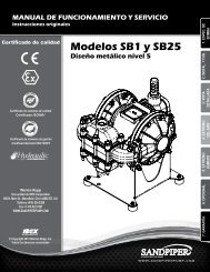
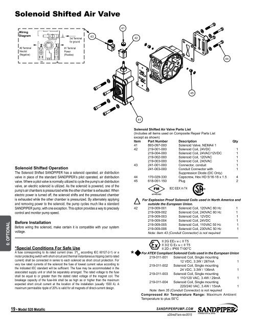
Solenoid Shifted Air Valve<br />
Wiring<br />
Diagram<br />
3rd Terminal<br />
for ground<br />
43<br />
41<br />
42<br />
#2 Terminal<br />
Neutral<br />
(Negative)<br />
#1 Terminal<br />
Power<br />
(Positive)<br />
44<br />
45<br />
41<br />
6: OPTIONAL<br />
Solenoid Shifted Operation<br />
The Solenoid Shifted SANDPIPER has a solenoid operated, air distribution<br />
valve in place of the standard SANDPIPER’s pilot operated, air distribution<br />
valve. Where a pilot valve is normally utilized to cycle the pump’s air distribution<br />
valve, an electric solenoid is utilized. As the solenoid is powered, one of the<br />
pump’s air chambers is pressurized while the other chamber is exhausted. When<br />
electric power is turned off, the solenoid shifts and the pressurized chamber<br />
is exhausted while the other chamber is pressurized. By alternately applying<br />
and removing power to the solenoid, the pump cycles much like a standard<br />
SANDPIPER pump, with one exception. This option provides a way to precisely<br />
control and monitor pump speed.<br />
Before Installation<br />
Before wiring the solenoid, make certain it is compatible with your system<br />
voltage.<br />
*Special Conditions For Safe Use<br />
A fuse corresponding to its rated current (max. 3*I rat<br />
according IEC 60127-2-1) or a<br />
motor protecting switch with short-circuit and thermal instantaneous tripping (set to rated<br />
current) shall be connected in series to each solenoid as short circuit protection. For<br />
very low rated currents of the solenoid the fuse of lowest current value according to<br />
the indicated IEC standard will be sufficient. The fuse may be accommodated in the<br />
associated supply unit or shall be separately arranged. The rated voltage to the fuse<br />
shall be equal to or greater than the stated rated voltage of the magnet coil. The<br />
breakage capacity of the fuse-link shall be as high as or higher than the maximum<br />
expected short circuit current at the location of the installation (usually 1500 A). A<br />
maximum permissible ripple of 20% is valid for all magnets of direct-current design.<br />
*<br />
Solenoid Shifted Air Valve Parts List<br />
(Includes all items used on Composite Repair Parts List<br />
except as shown)<br />
Item Part Number Description Qty<br />
41 893-097-000 Solenoid Valve, NEMA4 1<br />
42 219-001-000 Solenoid Coil, 24VDC 1<br />
219-004-000 Solenoid Coil, 24VAC/12VDC 1<br />
219-002-000 Solenoid Coil, 120VAC 1<br />
219-003-000 Solenoid Coil, 240VAC 1<br />
43 241-001-000 Connector, conduit 1<br />
241-003-000 Conduit Connector with 1<br />
Suppression Diode (DC Only)<br />
44 170-029-330 Capscrew, Hex HD 5/16-18 x 1.5 4<br />
45 618-051-150 Plug 2<br />
IEC EEX m T4<br />
For Explosion Proof Solenoid Coils used in North America and<br />
outside the European Union.<br />
42 219-009-001 Solenoid Coil, 120VAC 60 Hz 1<br />
219-009-002 Solenoid Coil, 240VAC 60 Hz 1<br />
219-009-003 Solenoid Coil, 12VDC 1<br />
219-009-004 Solenoid Coil, 24VDC 1<br />
219-009-005 Solenoid Coil, 110VAC 50 Hz 1<br />
219-009-006 Solenoid Coil, 230VAC 50 Hz 1<br />
Note: Item 43 (Conduit Connector) is not required<br />
II<br />
II<br />
2G EEx m c<br />
2G m<br />
II<br />
c<br />
T5<br />
T5<br />
II 3/2 G Ex m c II T5<br />
II<br />
II<br />
2D<br />
2D c IP65 T100°C<br />
c IP65 T100°C<br />
For ATEX Compliant Solenoid Coils used in the European Union<br />
219-011-001 Solenoid Coil, Single mounting<br />
12 VDC, 3.3W / 267mA 1<br />
219-011-002 Solenoid Coil, Single mounting<br />
24 VDC, 3.3W / 136mA 1<br />
219-011-003 Solenoid Coil, Single mounting<br />
110/120 VAC, 3.4W / 29mA 1<br />
219-011-004 Solenoid Coil, Single mounting<br />
220/240 VAC, 3.4W / 15mA 1<br />
Note: Item 35 (Conduit Connector) is not required<br />
Compressed Air Temperature Range: Maximum Ambient<br />
Temperature to plus 50°C<br />
19 • Model S20 Metallic<br />
sandpiperpump.com<br />
s20mdl1sm-rev0515