
You also want an ePaper? Increase the reach of your titles
YUMPU automatically turns print PDFs into web optimized ePapers that Google loves.
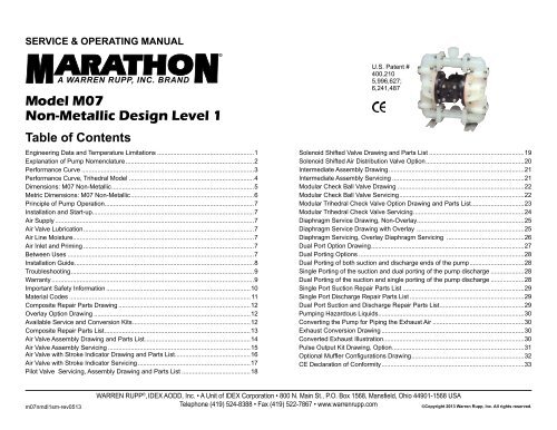
SERVICE & OPERATING MANUALModel M07Non-Metallic Design Level 1Table of ContentsEngineering Data and Temperature Limitations........................................................1Explanation of Pump Nomenclature..........................................................................2Performance Curve...................................................................................................3Performance Curve, Trihedral Model .......................................................................4Dimensions: M07 Non-Metallic..................................................................................5Metric Dimensions: M07 Non-Metallic.......................................................................6Principle of Pump Operation.....................................................................................7Installation and Start-up............................................................................................7Air Supply..................................................................................................................7Air Valve Lubrication..................................................................................................7Air Line Moisture.......................................................................................................7Air Inlet and Priming..................................................................................................7Between Uses...........................................................................................................7Installation Guide.......................................................................................................8Troubleshooting.........................................................................................................9Warranty....................................................................................................................9Important Safety Information...................................................................................10Material Codes........................................................................................................ 11Composite Repair Parts Drawing............................................................................12Overlay Option Drawing..........................................................................................12Available Service and Conversion Kits....................................................................12Composite Repair Parts List....................................................................................13Air Valve Assembly Drawing and Parts List.............................................................14Air Valve Assembly Servicing..................................................................................15Air Valve with Stroke Indicator Drawing and Parts List............................................16Air Valve with Stroke Indicator Servicing.................................................................17Pilot Valve Servicing, Assembly Drawing and Parts List........................................18U.S. Patent #400,2105,996,627;6,241,487Solenoid Shifted Valve Drawing and Parts List.......................................................19Solenoid Shifted Air Distribution Valve Option.........................................................20Intermediate Assembly Drawing..............................................................................21Intermediate Assembly Servicing............................................................................21Modular Check Ball Valve Drawing.........................................................................22Modular Check Ball Valve Servicing........................................................................22Modular Trihedral Check Valve Option Drawing and Parts List...............................23Modular Trihedral Check Valve Servicing................................................................24Diaphragm Service Drawing, Non-Overlay.............................................................25Diaphragm Service Drawing with Overlay ..............................................................25Diaphragm Servicing, Overlay Diaphragm Servicing .............................................26Dual Port Option Drawing........................................................................................27Dual Porting Options...............................................................................................28Dual Porting of both suction and discharge ends of the pump................................28Single Porting of the suction and dual porting of the pump discharge....................28Dual Porting of the suction and single porting of the pump discharge....................28Single Port Suction Repair Parts List......................................................................29Single Port Discharge Repair Parts List..................................................................29Dual Port Suction and Discharge Repair Parts List.................................................29Pumping Hazardous Liquids...................................................................................30Converting the Pump for Piping the Exhaust Air.....................................................30Exhaust Conversion Drawing..................................................................................30Converted Exhaust Illustration................................................................................30Pulse Output Kit Drawing, Option............................................................................31Optional Muffler Configurations Drawing.................................................................32CE Declaration of Conformity..................................................................................33m07nmdl1sm-rev0513WARREN RUPP ® , IDEX AODD, Inc. • A Unit of IDEX Corporation • 800 N. Main St., P.O. Box 1568, Mansfield, Ohio 44901-1568 USATelephone (419) 524-8388 • Fax (419) 522-7867 • www.warrenrupp.com©Copyright 2013 Warren Rupp, Inc. All rights reserved.
Quality SystemISO9001 CertifiedEnvironmentalManagement SystemISO14001 CertifiedU.S. Patent #5,851,109; 5,996,627;400,210; 6,241,487Other U.S. PatentsApplied forM07 Non-MetallicBall ValveDesign Level 1Air OperatedDouble Diaphragm PumpENGINEERING, PERFORMANCE& CONSTRUCTION DATAINTAKE/DISCHARGE PIPE SIZEInternal Threads ¾" NPT or ¾" BSP TaperedExternal Threads 1½" NPT or1½” BSP TaperedCAPACITY0 to 23 US gallons per minute(0 to 87 liters per minute)AIR VALVENo-lube, no-stalldesignSOLIDS-HANDLINGBall Valve S07B Models - Up to .15 in.(4mm)Trihedral Valve S07T Models - Up tp .36in(9.1mm) Diameter or .16in 2 area (10.3cm 2 )HEADS UP TO100 psi or 231 ft. of water(7 bar or 70 meters)DISPLACEMENT/STROKE.026 US gallon / .098 literCAUTION! Operating temperature limitations are as follows:Operating TemperaturesMaterials Maximum MinimumSantoprene ® : Injection molded thermoplastic elastomer with no fabric layer. Long mechanical flex life. Excellent abrasion 275°F -40°Fresistance. 135°C -40°CVirgin PTFE: Chemically inert, virtually impervious. Very few chemicals are known to react chemically with PTFE: molten alkali metals,turbulent liquid or gaseous fluorine and a few fluoro-chemicals such as chlorine trifluoride or oxygen difluoride which readily 220°F -35°Fliberate free fluorine at elevated temperatures. 104°C -37°CPVDF: 250°F 0°F121°C -18°CPolypropylene: 180°F 32°F82°C 0°CNitrile: General purpose, oil-resistant. Shows good solvent, oil, water and hydraulic fluid resistance. Should not be used 190°F -10°Fwith highly polar solvents like acetone and MEK, ozone, chlorinated hydrocarbons and nitro hydrocarbons. 88°C -23°CFKM (Fluorocarbon): Shows good resistance to a wide range of oils and solvents; especially all aliphatic, aromatic and halogenated 350°F -40°Fhydrocarbons, acids, animal and vegetable oils. Hot water or hot aqueous solutions (over 70°F) will attack FKM. 177°C -40°CNylon:For specific applications, always consult the Warren Rupp “Chemical Resistance Chart”180°F82°C32°F0°CCAUTION: Nonmetallic pumps and plastic components are not UV stabilized. Ultraviolet radiation can damage these parts and negatively affect material properties.Do not expose to UV light for extended periods of time.Marathon ® pumps are designed to be powered only by compressed air.m07nmdl1sm-rev0513 Models M07 Non-Metallic Page 1
M07 Non-Metallic · Design Level 1· Ball ValveTypeS07B1P1PPNS000.PumpBrandPumpSizeCheckValveTypeDesignLevelWettedMaterialS 07 B 1 PDiaphragm/Check ValveOptions1 PP N S 0 00. 17 (8)m07nmdl1sm-rev0513 Models M07 Non-Metallic Page 2CheckValveSeatNon-WettedMaterialOptionsS07B1P2PPNS000. S 07 B 1 P 2 P P N S 0 00. 17 (8)S07B1K1KPNS000. S 07 B 1 K 1 K P N S 0 00. 21 (9.5)S07B1K2KPNS000. S 07 B 1 K 2 K P N S 0 00. 21 (9.5)S07B1N1NPNS000. S 07 B 1 N 1 N P N S 0 00. 18 (9)S07B1N2NPNS000. S 07 B 1 N 2 N P N S 0 00. 18 (9)S07T1P7PPNS000. S 07 T 1 P 7 P P N S 0 00. 17 (8)S07T1P8PPNS000.S07T1PBPPNS000.SS0707TT11PP8BPPPPNNSS0000.00.17 (8)17 (8)S07B1P1PPBS000. S 07 B 1 P 1 P P B S 0 00. 17 (8)S07B1P2PPBS000. S 07 B 1 P 2 P P B S 0 00. 17 (8)S07B1K1KPBS000. S 07 B 1 K 1 K P B S 0 00. 21 (9.5)S07B1K2KPNS000. S 07 B 1 K 2 K P B S 0 00. 21 (9.5)S07B1N1NPBS000. S 07 B 1 N N P B S 0 00. 18 (9)S07B1N2NPBS000. S 07 B 1 N 2 N P B S 0 00. 18 (9)S07T1P7PPBS000. S 07 T 1 P 7 P P B S 0 00. 21 (9.5)S07T1P8PPBS000.S07T1PBPPBS000.Pump BrandM= Marathon ®Pump Size07= 3/4"Check Valve TypeB= BallT= TihedralDesign Level1= Design Level 1Wetted MaterialK= PVDFN= NylonP= PolypropyleneSS0707TT11PPDaiphragm/Check Valve Materials1= Santoprene/Santoprene2= Virgin PTFE-SantopreneBackup/Virgin PTFE7= Santoprene/Nitrile8= Virgin PTFE-SantopreneBackup/FKMB= Nitrile/NitrileZ= One-Piece Bonded/PTFECheck Valve SeatK= PVDFN= NylonP= PolypropyleneNon-Wetted Material OptionsP= PolypropyleneI= Polypropylene with PTFEHardware8 PBPPPPorting OptionsN= NPT Threads1= Dual Porting (NPT)2= Top Dual Porting (NPT)3= Bottom Dual Porting (NPT)B= BSP Threads (tapered)4= Dual Porting (BSP) (tapered)5= Top Dual Porting (BSP) (tapered)6= Bottom Dual Porting (BSP) (tapered)Pump StyleS= StandardPump Options0= None1= Sound Dampening2= Mesh Muffler6= Metal MufflerPortingOptionsBBPumpStyleSSPumpOptions00KitOptions00.00.ShippingWeightlbs (kg)21 (9.5)21 (9.5)Kit Options00.= NoneP0.= 10-30VDC Pulse Output KitP1.= Intrinsically-Safe 5-30VDC,110/120VAC, 220/240VACPulse Output KitP2.= 110/120 or 220/240VAC Pulse Output KitE0.= Solenoid Kit w/24VDC CoilE1.= Solenoid Kit 24VDC Explosion-Proof CoilE2.= Solenoid Kit w/24VAC/12VDC CoilE3.= Solenoid Kit w/12VDC Explosion-Proof CoilE4.= Solenoid Kit w/110VAC CoilE5.= Solenoid Kit w/110VAC 60 Hz Explosion-Proof CoilE6.= Solenoid Kit w/220VAC CoilE7.= Solenoid Kit w/220VAC 60 Hz Explosion-Proof CoilE8.= Solenoid Kit w/110VAC 50 Hz Explosion-Proof CoilE9.= Solenoid Kit w/230VAC 50 Hz Explosion-Proof CoilSP= Stroke Indicator Pins
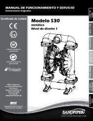
M07 Non-Metallic Performance Curve CurveBAR76PSI10090804 (7)100 PSI (6.8 Bar)MODEL S07 Ball Valve Non-Metallic Performance CurvePerformance based on the following: elastomer fitted pump, flooded suction, water at ambient conditions.The use of other materials and varying hydraulic conditions may result in deviations in excess of 5%.8 (13.5)12 (20)HEAD5437060504080 PSI (5.44 Bar)60 PSI (4.08 Bar)16 (27)20 (34)FEETNPSHRMETERS210302010040 PSI (2.72 Bar)20 PSI (1.36 Bar) Air Inlet Pressure1050 2 4 6 8 10 12 14 16 18 20 22 24 26U.S. Gallons per minute302520159.17.664.531.5010 20 30 40 50 60 70 80 90 100Liters per minuteCAPACITYm07nmdl1sm-rev0513 Models M07 Non-Metallic Page 3
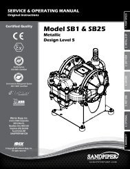
M07 Non-Metallic Performance Curve, Trihedral ModelBAR76PSI10090802 (3.5)4 (7)6 (10)100 PSI (6.8 Bar)8 (13.5)10 (17)MODEL S07 Trihedral Valve Performance CurvePerformance based on the following: elastomer fitted pump, flooded suction, water at ambient conditions.The use of other materials and varying hydraulic conditions may result in deviations in excess of 5%.80 PSI (5.44 Bar)HEAD5470605012 (20)14 (24)16 (27)18 (30.4)NPSHR60 PSI (4.08 Bar)340FEETMETERS210302010040 PSI(2.72 Bar)20 PSI (1.36 Bar)Air Inlet Pressure1050 1 2 3 4 5 6 7 8 9 10 11 12 13 14 15302520159.17.664.531.5U.S. Gallons per minute05 10 15 20 25 30 35 40 45 50 55Liters per minuteCAPACITYm07nmdl1sm-rev0513 Models M07 Non-Metallic Page 4
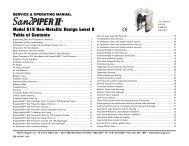
Dimensions: M07 Non-MetallicDimensions in InchesDimensional tolerance: ± 1 /8"*Discharge Port¾" NPT (Internal)1½" NPT (External)Manifold Can Rotate 90°From Vertical Centerline.StandardEncapsulated Muffler:3/8" NPT Exhaust PortFor Optional MufflerStyles or Piping ExhaustAir in SubmergedApplications.Air Inlet ¼" NPT*Suction Port¾" NPT (Internal)1½" NPT (External)Bolt Patternis SymmetricalAbout Centerlines*Both Suction and DischargePorts are Available In:¾" BSPT (Tapered) (Internal)1½" BSPT (Tapered) (External)DimensionStandard PumpPulse Output KitMesh MufflerAB4 1/16" 7 1/16"4 1/16" 7 1/16"5 3/4" 9 15/16"m07nmdl1sm-rev0513 Models M07 Non-Metallic Page 5
Metric Dimensions: M07 Non-MetallicDimensions in MillimetersDimensional tolerance: ±3mm*Discharge Port¾" NPT (Internal)1½" NPT (External)Manifold can Rotate 90°From Vertical Centerline.StandardEncapsulated Muffler:3/8" NPT Exhaust PortFor Optional MufflerStyles or Piping ExhaustAir in SubmergedApplications.Air Inlet¼" NPT*Suction Port¾" NPT (Internal)1½" NPT (External)Bolt PatternIs SymmetricalAbout Centerlines*Both Suction andDischarge Ports areAvailable In:¾" BSPT (Tapered) (Internal)1½" BSPT (Tapered) (External)R5/32"4 PlacesDimensionStandard PumpPulse Output KitMesh MufflerA103mm103mm146mmB179mm224mm222mmm07nmdl1sm-rev0513 Models M07 Non-Metallic Page 6
PRINCIPLE OF PUMP OPERATIONThis ball type check valve pumpis powered by compressed air and isa 1:1 ratio design. The inner side ofone diaphragm chamber is alternatelypressurized while simultaneouslyexhausting the other inner chamber.This causes the diaphragms, whichare connected by a common rodsecured by plates to the centers of thediaphragms, to move in a reciprocatingaction. (As one diaphragm performs thedischarge stroke the other diaphragm ispulled to perform the suction stroke inthe opposite chamber.) Air pressure isapplied over the entire inner surface ofthe diaphragm while liquid is dischargedfrom the opposite side of the diaphragm.The diaphragm operates in a balancedcondition during the discharge strokewhich allows the pump to be operatedat discharge heads over 200 feet (61meters) of water.For maximum diaphragm life, keepthe pump as close to the liquid beingpumped as possible. Positive suctionhead in excess of 10 feet of liquid(3.048 meters) may require a backpressure regulating device to maximizediaphragm life.Alternate pressurizing andexhausting of the diaphragm chamberis performed by an externally mounted,pilot operated, four way spool typeair distribution valve. When the spoolshifts to one end of the valve body, inletpressure is applied to one diaphragmchamber and the other diaphragmchamber exhausts. When the spoolshifts to the opposite end of the valvebody, the pressure to the chambersis reversed. The air distribution valvespool is moved by a internal pilot valvewhich alternately pressurizes one endof the air distribution valve spool whileexhausting the other end. The pilot valveis shifted at each end of the diaphragmstroke when a actuator plunger iscontacted by the diaphragm plate. Thisactuator plunger then pushes the endof the pilot valve spool into position toactivate the air distribution valve.The chambers are connected withmanifolds with a suction and dischargecheck valve for each chamber,maintaining flow in one directionthrough the pump.INSTALLATION AND START-UPLocate the pump as close to theproduct being pumped as possible.Keep the suction line length andnumber of fittings to a minimum. Do notreduce the suction line diameter.For installations of rigid piping,short sections of flexible hose shouldbe installed between the pumpand the piping. The flexible hosereduces vibration and strain to thepumping system. A surge suppressoris recommended to further reducepulsation in flow.AIR SUPPLYAir supply pressure cannot exceed100 psi (7 bar). Connect the pumpair inlet to an air supply of sufficientcapacity and pressure required fordesired performance. When the airsupply line is solid piping, use a shortlength of flexible hose not less than1/2" (13mm) in diameter betweenthe pump and the piping to reducestrain to the piping. The weight of theair supply line, regulators and filtersmust be supported by some meansother than the air inlet cap. Failure toprovide support for the piping may resultin damage to the pump. A pressureregulating valve should be installedto insure air supply pressure does notexceed recommended limits.AIR VALVE LUBRICATIONThe air distribution valve and thepilot valve are designed to operateWITHOUT lubrication. This is thepreferred mode of operation. There maybe instances of personal preferenceor poor quality air supplies whenlubrication of the compressed airsupply is required. The pump air systemwill operate with properly lubricatedcompressed air supply. Properlubrication requires the use of an air linelubricator (available from Warren Rupp)set to deliver one drop of SAE 10 nondetergentoil for every 20 SCFM (9.4liters/sec.) of air the pump consumesat the point of operation. Consult thepump’s published Performance Curveto determine this.AIR LINE MOISTUREWater in the compressed air supplycan create problems such as icing orfreezing of the exhaust air, causingthe pump to cycle erratically or stopoperating. Water in the air supply canbe reduced by using a point-of-useair dryer to supplement the user’s airdrying equipment. This device removeswater from the compressed air supplyand alleviates the icing or freezingproblems.AIR INLET AND PRIMINGTo start the pump, open the air valveapproximately 1/2" to 3/4" turn. Afterthe pump primes, the air valve can beopened to increase air flow as desired.If opening the valve increases cyclingrate, but does not increase the rate offlow, cavitation has occurred. The valveshould be closed slightly to obtain themost efficient air flow to pump flow ratio.BETWEEN USESWhen the pump is used for materialsthat tend to settle out or solidify whennot in motion, the pump should beflushed after each use to preventdamage. (Product remaining in thepump between uses could dry out orsettle out. This could cause problemswith the diaphragms and check valvesat restart.) In freezing temperaturesthe pump must be completely drainedbetween uses in all cases.m07nmdl1sm-rev0513 Models M07 Non-Metallic Page 7
INSTALLATION GUIDETop Discharge Ball Valve Unit1Available fromWarren RuppDA07 Surge DampenerSurgeDampenerLimited to100 psi12020-049-000 Filter/Regulator3Air DryerCAUTIONThe air exhaust should bepiped to an area for safedisposition of the productbeing pumped, in the eventof a diaphragm failure.23m07nmdl1sm-rev0513 Models M07 Non-Metallic Page 8
TROUBLESHOOTINGPossible Symptoms:• Pump will not cycle.• Pump cycles, but produces no flow.• Pump cycles, but flow rate isunsatisfactory.• Pump cycle seems unbalanced.• Pump cycle seems to produceexcessive vibration.What to Check: Excessive suction liftin system.Corrective Action: For lifts exceeding20 feet (6 meters), filling the pumpingchambers with liquid will prime thepump in most cases.What to Check: Excessive floodedsuction in system.Corrective Action: For floodedconditions exceeding 10 feet (3 meters)of liquid, install a back pressure device.What to Check: System head exceedsair supply pressure.Corrective Action: Increase theinlet air pressure to the pump. Mostdiaphragm pumps are designed for 1:1pressure ratio at zero flow.What to Check: Air supply pressure orvolume exceeds system head.Corrective Action: Decrease inletair pressure and volume to thepump as calculated on the publishedPERFORMANCE CURVE. Pump iscavitating the fluid by fast cycling.What to Check: Undersized suctionline.Corrective Action: Meet or exceedpump connection recommendationsshown on the DIMENSIONALDRAWING.What to Check: Restricted orundersized air line.Corrective Action: Install a largerair line and connection. Refer to airinlet recommendations shown in yourpump’s SERVICE MANUAL.What to Check: Check ESADS, theExternally Serviceable Air DistributionSystem of the pump.Corrective Action: Disassemble andinspect the main air distribution valve,pilot valve and pilot valve actuators.Refer to the parts drawing and air valvesection of the SERVICE MANUAL.Check for clogged discharge or closedvalve before reassembly.What to Check: Rigid pipe connectionsto pump.Corrective Action: Install flexibleconnectors and a surge suppressor.What to Check: Blocked air exhaustmuffler.Corrective Action: Remove mufflerscreen, clean or de-ice and reinstall.Refer to the Air Exhaust section of yourpump SERVICE MANUAL.What to Check: Pumped fluid in airexhaust muffler.Corrective Action: Disassemblepump chambers. Inspect for diaphragmrupture or loose diaphragm plateassembly. Refer to the DiaphragmReplacement section of your pumpSERVICE MANUAL.What to Check: Suction side airleakage or air in product.Corrective Action: Visually inspectall suction side gaskets and pipeconnections.What to Check: Obstructed checkvalve.Corrective Action: Disassemble thewet end of the pump and manuallydislodge obstruction in the check valvepocket. Refer to the Check Valvesection of the pump SERVICE MANUALfor disassembly instructions.What to Check: Worn or misalignedcheck valve or check valve seat.Corrective Action: Inspect checkvalves and seats for wear and properseating. Replace if necessary. Referto Check Valve section of the pumpSERVICE MANUAL for disassemblyinstructions.What to Check: Blocked suction line.Corrective Action: Remove or flushobstruction. Check and clear all suctionscreens and strainers.What to Check: Blocked dischargeline.Corrective Action: Check forobstruction or closed discharge linevalves.What to Check: Blocked pumpingchamber.Corrective Action: Disassembleand inspect the wetted chambersof the pump. Remove or flush anyobstructions. Refer to the pumpSERVICE MANUAL for disassemblyinstructions.What to Check: Entrained air or vaporlock in one or both pumping chambers.Corrective Action: Purge chambersthrough tapped chamber vent plugs.PURGING THE CHAMBERS OF AIRCAN BE DANGEROUS! Contact theWarren Rupp Technical Service Teambefore performing this procedure. Amodel with top-ported discharge willreduce or eliminate problems withentrained air.If your pump continues to performbelow your expectations, contact yourlocal Warren Rupp Distributor or factoryTechnical Service Team for a serviceevaluation.WARRANTYRefer to the enclosed Warren RuppWarranty Certificate.m07nmdl1sm-rev0513 Models M07 Non-Metallic Page 9
RECYCLINGMany components of SANDPIPER ® AODDpumps are made of recyclable materials (seechart on page 9 for material specifications).We encourage pump users to recycle wornout parts and pumps whenever possible, afterany hazardous pumped fluids are thoroughlyflushed.Pump complies with EN809 Pumping Directive,Directive 2006/42/EC Machinery, according toAnnex VIII. For reference to the declarationsof conformity visit: www.warrenrupp.com.IMPORTANT SAFETYINFORMATIONIMPORTANTRead these safety warningsand instructions in thismanual completely, beforeinstallation and start-upof the pump. It is the responsibility of thepurchaser to retain this manual for reference.Failure to comply with the recommendationsstated in this manual will damage the pump,and void factory warranty.CAUTIONBefore pump operation,inspect all gasketedfasteners for loosenesscaused by gasket creep. Retorqueloose fasteners toprevent leakage. Follow recommended torquesstated in this manual.WARNINGBefore maintenance orrepair, shut off the compressedair line, bleed thepressure, and disconnectthe air line from the pump.The discharge line may be pressurized and mustbe bled of its pressure.WARNINGIn the event of diaphragmrupture, pumped materialmay enter the air end of thepump, and be dischargedinto the atmosphere. Ifpumping a product which is hazardous or toxic,the air exhaust must be piped to an appropriatearea for safe disposition.WARNINGTake action to prevent staticsparking. Fire or explosioncan result, especially whenhandling flammable liquids.The pump, piping, valves,containers or other miscellaneous equipmentmust be grounded.WARNINGThis pump is pressurizedinternally with air pressureduring operation. Alwaysmake certain that all boltingis in good condition andthat all of the correctbolting is reinstalled during assembly.WARNINGWhen used for toxic oraggressive fluids, the pumpshould always be flushedclean prior to disassembly.WARNINGBefore doing any maintenanceon the pump,be certain all pressure iscompletely vented from thepump, suction, discharge,piping, and all otheropenings and connections. Be certain the airsupply is locked out or made non‐operational,so that it cannot be started while work is beingdone on the pump. Be certain that approvedeye protection and protective clothing are wornall times in the vicinity of the pump. Failure tofollow these recommendations may result inserious injury or death.WARNINGAirborne particles andloud noise hazards.Wear ear and eyeprotection.m07nmdl1sm-rev0513 Models M07 Non-Metallic Page 10
Material CodesThe Last 3 Digits of Part Number000 Assembly, sub-assembly;and some purchased items010 Cast Iron012 Powered Metal015 Ductile Iron020 Ferritic Malleable Iron025 Music Wire080 Carbon Steel, AISI B-1112100 Alloy 20110 Alloy Type 316 Stainless Steel111 Alloy Type 316 Stainless Steel(Electro Polished)112 Alloy C113 Alloy Type 316 Stainless Steel(Hand Polished)114 303 Stainless Steel115 302/304 Stainless Steel117 440-C Stainless Steel (Martensitic)120 416 Stainless Steel(Wrought Martensitic)123 410 Stainless Steel(Wrought Martensitic)148 Hardcoat Anodized Aluminum149 2024-T4 Aluminum150 6061-T6 Aluminum151 6063-T6 Aluminum152 2024-T4 Aluminum (2023-T351)154 Almag 35 Aluminum155 356-T6 Aluminum156 356-T6 Aluminum157 Die Cast Aluminum Alloy #380158 Aluminum Alloy SR-319159 Anodized Aluminum162 Brass, Yellow, Screw Machine Stock165 Cast Bronze, 85-5-5-5166 Bronze, SAE 660170 Bronze, Bearing Type,Oil Impregnated175 Die Cast Zinc180 Copper Alloy305 Carbon Steel, Black Epoxy Coated306 Carbon Steel, Black PTFE Coated307 Aluminum, Black Epoxy Coated308 Stainless Steel, Black PTFE Coated309 Aluminum, Black PTFE Coated310 PVDF Coated330 Zinc Plated Steel331 Chrome Plated Steel332 Aluminum, Electroless Nickel Plated333 Carbon Steel, ElectrolessNickel Plated335 Galvanized Steel336 Zinc Plated Yellow Brass337 Silver Plated Steel340 Nickel Plated342 Filled Nylon353 Geolast; Color: Black354 Injection Molded #203-40 Santoprene-Duro 40D +/-5; Color: RED355 Thermal Plastic356 Hytrel357 Injection Molded Polyurethane358 Urethane Rubber(Some Applications) (Compression Mold)359 Urethane Rubber360 Nitrile Rubber. Color coded: RED361 FDA Accepted Nitrile363 FKM (Fluorocarbon).Color coded: YELLOW364 E.P.D.M. Rubber. Color coded: BLUE365 Neoprene Rubber.Color coded: GREEN366 FDA Accpeted Nitrile368 FDA Accpeted EPDM370 Butyl Rubber. Color coded: BROWN371 Philthane (Tuftane)374 Carboxylated Nitrile375 Fluorinated Nitrile378 High Density Polypropylene379 Conductive Nitrile405 Cellulose Fibre408 Cork and Neoprene425 Compressed Fibre426 Blue Gard440 Vegetable Fibre465 Fibre500 Delrin 500501 Delrin 570502 Conductive Acetal, ESD-800503 Conductive Acetal, Glass-Filled505 Acrylic Resin Plastic506 Delrin 150520 Injection Molded PVDF Natural color521 Conductive PVDF540 Nylon541 Nylon542 Nylon544 Nylon Injection Molded550 Polyethylene551 Glass Filled Polypropylene552 Unfilled Polypropylene553 Unfilled Polypropylene555 Polyvinyl Chloride556 Black Vinyl557 Conductive Polypropylene558 Conductive HDPE559 Glass-Filled Conductive Polypropylene570 Rulon II580 Ryton590 Valox591 Nylatron G-S592 Nylatron NSB600 PTFE (virgin material)Tetrafluorocarbon (TFE)601 PTFE (Bronze and moly filled)602 Filled PTFE603 Blue Gylon604 PTFE606 PTFE607 Envelon608 Conductive PTFE610 PTFE Integral Silicon611 PTFE Integral FKM632 Neoprene/Hytrel633 FKM (Fluorocarbon)/PTFE634 EPDM/PTFE635 Neoprene/PTFE637 PTFE, FKM (Fluorocarbon)/PTFE638 PTFE, Hytrel/PTFE639 Nitrile/TFE643 Santoprene/EPDM644 Santoprene/PTFE650 Bonded Santoprene and PTFE654 Santoprene Diaphragm, PTFE OverlayBalls and seals656 Santoprene Diaphragm andCheck Balls/EPDM Seats661 EPDM/SantopreneDelrin and Hytrel are registered tradenamesof E.I. DuPont.Gylon is a registered tradename of Garlock, Inc.Nylatron is a registered tradename ofPolymer Corp.Santoprene is a registered tradename ofMonsanto Corp.Rulon II is a registered tradename ofDixion Industries Corp.Ryton is a registered tradename ofPhillips Chemical Co.Valox is a registered tradename ofGeneral Electric Co.m07nmdl1sm-rev0513 Models M07 Non-Metallic Page 11
Composite Repair Parts DrawingAVAILABLE SERVICE AND CONVERSION KITS476-219-000 AIR END KITSeals, O-rings, Gaskets,Bumpers Retaining Rings, AirValve Assembly and Pilot ValveAssembly.476-220-000 AIR END KITfor pumps equipped with StrokeIndicator (same components asabove, except Valve Assemblywith pins replaces Air ValveStandard).476-166-354 WETTED END KITSantoprene Diaphragms, NitrileSpacer Gaskets, SantopreneCheck Balls and TFE Seals.476-166-650 WETTED END KITPTFE/Santoprene BondDiaphragm, PTFE Check Balls andPTFE Seals.476-166-654 WETTED END KITSantoprene Diaphragms, TFE OverlayDiaphragm, TFE Check Balls and TFESeals.476-180-657 WETTED END KIT (S07T)Santoprene Diaphragms, NitrileTrihedral Valve Components,Nitrile Spacer Gaskets, and TFEManifold Seals.476-180-658 WETTED END KIT (S07T)Santoprene Backup Diaphragms, TFEOverlay Diaphragms, FKM TrihedralValve Components, and TFE ManifoldSeals.476-180-360 WETTED END KITS (S07T)Nitrile Diaphragms, Nitrile TrihedralValves, PTFE Seals.m07nmdl1sm-rev0513 Models M07 Non-Metallic Page 12
Composite Repair Parts ListNOTE: See Pages 14 and 16 For Full Explanation of Air Valve Options.ITEM PART NUMBER DESCRIPTION QTY1 031-166-000 Air Valve Assembly (Integral Muffler) 1031-166-002 Air Valve Assembly (with PTFE Coated Hardware) 1031-167-000 Air Valve Assembly (with stroke Indicator Pins) 1031-167-002 Air Valve Assembly (with Stroke Indicator Pins and 1PTFE Coated Hardware)031-168-000 Air Valve Assembly (Optional Mufflers) 1031-169-000 Air Valve Assembly (Stroke Indicator & 1Optional Mufflers)031-176-000 Air Valve (High Temperature) 1031-177-000 Air Valve (High Temperature With Mufflers) 12 050-028-354 Ball, Check Valve 4050-028-600 Ball, Check Valve 43 095-091-000 Pilot Valve Assembly 1095-091-003 Pilot Valve Assembly (Conductive Acetal) 14 114-023-551 Bracket, Intermediate 15 115-141-115 Bracket, Mounting 26 132-034-360 Bumper, Diaphragm 27 135-036-506 Bushing, Plunger 28 165-110-551 Cap, Air Inlet 19 171-062-115 Capscrew, Flanged 5/16-18 x 1.00 8171-062-308 Capscrew, Flanged 5/16-18 x 1.00 8171-075-115 Capscrew, Flanged 5/16-18 x 1.00 410 171-063-115 Capscrew, Flanged 5/16-18 x 1.25 24171-063-308 Capscrew, Flanged 5/16-18 x 1.25 2411 171-064-115 Capscrew, Flanged 5/16-18 x 1.50 12171-064-308 Capscrew, Flanged 5/16-18 x 1.50 1212 171-066-115 Capscrew, Flanged 1/4-20 x 1.25 8171-066-308 Capscrew, Flanged 1/4-20 x 1.25 813 196-162-520 Chamber, Outer 2196-162-542 Chamber, Outer 2196-162-552 Chamber, Outer 214 286-095-354 Diaphragm 2286-095-360 Diaphragm 2286-116-000 Diaphragm, One-Piece Bonded 215 286-096-600 Diaphragm, Overlay 216 312-107-520 Elbow 4312-107-542 Elbow 4312-107-552 Elbow 4ITEM PART NUMBER DESCRIPTION QTY17 360-099-360 Gasket, Spacer (Use with TPE Diaphragms Only) 218 360-100-360 Gasket, Air Inlet 119 360-101-360 Gasket, Pilot Valve 120 360-102-360 Gasket, Air Valve 121 518-139-520 Manifold (NPT) 2518-139-520E Manifold (BSPT), tapered 2518-139-542 Manifold (NPT) 2518-139-542E Manifold (BSPT), tapered 2518-139-552 Manifold (NPT) 2518-139-552E Manifold (BSPT), tapered 222 530-023-000 Muffler 1530-024-000 Muffler 123 544-005-115 Nut, Flanged 5/16-18 36544-005-308 Nut, Flanged 5/16-18 3624 560-001-360 O-ring 225 612-091-520 Plate, Outer Diaphragm 2612-091-542 Plate, Outer Diaphragm 2612-091-552 Plate, Outer Diaphragm 226 612-177-330 Plate, Inner Diaphragm 2612-221-330 Plate, Inner (use with 2 One-PieceBonded Diaphragm Only) 227 620-019-115 Plunger, Actuator 228 670-050-520 Retainer, Ball 4670-050-542 Retainer, Ball 4670-050-552 Retainer, Ball 429 675-042-115 Ring, Retaining 230 685-056-120 Rod, Diaphragm 131 720-012-360 Seal, Diaphragm Rod 232 720-046-600 Seal, Manifold 433 720-051-600 Seal, Check Valve Retainer 834 722-081-520 Seat, Check Valve 4722-081-542 Seat, Check Valve 4722-081-552 Seat, Check Valve 4NOT SHOWN:535-069-000 Nameplatem07nmdl1sm-rev0513 Models M07 Non-Metallic Page 13
Air Distribution Valve Assembly Drawingmain air valve assembly parts listItem Part Number Description Qty1 031-166-000 Air Valve Assembly 11-A 095-106-551 Body, Air Valve 11-B 031-132-000 Sleeve and Spool Set 11-C 560-101-360 O-Ring 81-E 165-122-551 End Cap 21-F 560-026-360 O-Ring 21-G 675-062-115 End Cap Retainer 21-H 530-031-550 Muffler 11-I 165-109-551 Muffler Cap 11-J 710-011-115 Self-Tapping Screw 4For Pumps with Virgin PTFE coated hardware:1 031-166-002 Air Valve Assembly 11-G 675-062-308 End Cap Retainer 21-J 710-011-308 Self Tapping Screw 4(Includes all other items used on 031-166-000 above)For Pumps with alternate Mesh or Sound Dampening Mufflers or PipedExhaust:1 031-168-000 Air Valve Assembly 1(Includes all items used on 031-166-000 above minus 1-H, 1-I and 1-J)m07nmdl1sm-rev0513 Models M07 Non-Metallic Page 14
AIR DISTRIBUTION VALVESERVICINGTo service the air valve first shutoff the compressed air, bleed pressurefrom the pump, and disconnect the airsupply line from the pump.STEP #1: See COMPOSITEREPAIR PARTS DRAWING.Using a 3/8" wrench or socket,remove the four hex flanged capscrews(item 12). Remove the air valveassembly from the pump.STEP #2: Disassembly of the airvalve.To access the internal air valvecomponents first remove the two endcap retainers (item 1-G) by insertinga small flat screwdriver into the twoslotted grooves on the valve body andgently lifting the retainers out.Next remove the two end caps (item1-E) by grasping the pull tab with fingerand thumb or pliers and tugging. Inspectthe two o‐rings (items 1-C and 1-F) oneach end cap for wear or cuts. Replacethe o-rings if necessary.Remove the spool (part of item1-B) from the sleeve. Be careful not toscratch or damage the outer diameterof the spool. Wipe spool with a softclean cloth and inspect for scratchesor abrasive wear.Inspect the inner diameter of thesleeve (part of item 1-B) for dirt,scratches, or other contaminants.Remove the sleeve if needed andreplace with a new sleeve and spoolset (item 1-B). Note: The sleeve andspool set is match-ground to a specifiedclearance. Sleeves and spools cannotbe interchanged.STEP #3: Reassembly of the airdistribution valve.Install one end cap with o-rings(items 1-E, 1-C, and 1-F) into one end ofthe air valve body (item 1-A). Insert oneend cap retainer (item 1-G) into the twosmaller holes, align with groove in theend cap, and push until the closed endof the retainer is below the flat surfaceof the valve body.Remove the new sleeve and spoolset (item 1-B) from the plastic bag.Carefully remove the spool from thesleeve. Install the six o-rings (item 1-C)into the six grooves on the sleeve. Applya light coating of grease to the o-ringsbefore installing the sleeve into thevalve body. Align the slots in the sleevewith the slots in the valve body. Insertthe spool into the sleeve. Be carefulnot to scratch or damage the spoolduring installation. Push the spool inuntil the pin touches the end cap on theopposite end.Install the remaining end cap witho-rings and retainer.Fasten the air valve assembly (item1) and gasket (item 23) to the pump,using the four hex flanged capscrews(item 12).Connect the compressed air line tothe pump. The pump is now ready foroperation.IMPORTANTRead these instructionscompletely, beforeinstallation and start-up. Itis the responsibility of thepurchaser to retain this manual for reference.Failure to comply with the recommendationsstated in this manual will damage the pump,and void factory warranty.m07nmdl1sm-rev0513 Models M07 Non-Metallic Page 15
Air Valve with Stroke Indicator Assembly Drawing, Parts List1-K 1-H1-J1-B1-F1-E1-B1-D1-C1-Imain air valve assembly parts list1-D1-F1-CItem Part Number Description Qty1 031-167-000 Air Valve Assembly 11-A 095-106-559 Body, Air Valve 11-B 031-134-000 Sleeve and Spool Set 11-C 560-101-360 O-Ring 81-D 132.030.552 Bumper 21-E 165-123-147 End Cap 21-F 560-029-360 O-Ring 21-G 675-062-115 End Cap Retainer 21-H 210-008-330 Safety Clip 11-I 530-031-550 Muffler 11-J 165-109-559 Muffler Cap 11-K 710-011-115 Self-Tapping Screw 41-E1-G1-AFor Pumps with Virgin PTFE coated hardware:1 031-167-002 Air Valve Assembly 11-G 675-062-308 End Cap Retainer 21-J 710-011-308 Self Tapping Screw 4(Includes all other items used on 031-166-000 above)For Pumps with alternate Mesh or Sound Dampening Mufflers or PipedExhaust:1 031-169-000 Air Valve Assembly 1(Includes all items used on 031-167-000 above minus 1-H, 1-I and 1-J)m07nmdl1sm-rev0513 Models M07 Non-Metallic Page 16
AIR DISTRIBUTION VALVE WITHSTROKE INDICATOR OPTIONSERVICINGTo service the air valve first shutoff the compressed air, bleed pressurefrom the pump, and disconnect the airsupply line from the pump.STEP #1: See COMPOSITEREPAIR PARTS DRAWING.Using a 3/8" wrench or socket,remove the four hex flanged capscrews(item 12). Remove the air valveassembly from the pump.STEP #2: Disassembly of the airvalve.To access the internal air valvecomponents first remove the two endcap retainers (item 1-G) by insertinga small flat screwdriver into the twoslotted grooves on the valve body andgently lifting the retainers out.Next remove the two end caps (item1-E) by grasping the pull tab with fingerand thumb or pliers and tugging. Inspectthe two o‐rings (items 1-C and 1-F) oneach end cap for wear or cuts. Replacethe o-rings if necessary.Remove the spool (part of item1-B) from the sleeve. Be careful not toscratch or damage the outer diameterof the spool. Wipe spool with a softclean cloth and inspect for scratchesor abrasive wear.Inspect the inner diameter of thesleeve (part of item 1-B) for dirt,scratches, or other contaminants.Remove the sleeve if needed andreplace with a new sleeve and spoolset (item 1-B). Note: The sleeve andspool set is match-ground to a specifiedclearance. Sleeves and spools cannotbe interchanged.STEP #3: Reassembly of the airdistribution valve.Install one end cap with o-rings(items 1-E, 1-C, and 1-F) into one end ofthe air valve body (item 1-A). Insert oneend cap retainer (item 1-G) into the twosmaller holes, align with groove in theend cap, and push until the closed endof the retainer is below the flat surfaceof the valve body.Remove the new sleeve and spoolset (item 1-B) from the plastic bag.Carefully remove the spool from thesleeve. Install the six o-rings (item 1-C)into the six grooves on the sleeve. Applya light coating of grease to the o-ringsbefore installing the sleeve into thevalve body. Align the slots in the sleevewith the slots in the valve body. Insertthe spool into the sleeve. Be carefulnot to scratch or damage the spoolduring installation. Push the spool inuntil the pin touches the end cap on theopposite end.Install the remaining end cap witho-rings and retainer.Fasten the air valve assembly (item1) and gasket (item 23) to the pump,using the four hex flanged capscrews(item 12).Connect the compressed air line tothe pump. The pump is now ready foroperation.IMPORTANT: Remove the safetyclip. The pump will not function properlyuntil it is removed. The pump is nowready for operation.IMPORTANTRead these instructionscompletely, beforeinstallation and start-up.It is the responsibility ofthe purchaser to retainthis manual for reference. Failure tocomply with the recommendations statedin this manual will damage the pump, andvoid factory warranty.m07nmdl1sm-rev0513 Models M07 Non-Metallic Page 17
Pilot Valve Servicing, Assembly Drawing & Parts Listpilot valve assembly parts listItem Part Number Description Qty3 095-091-000 Pilot Valve Assembly 13-A 095-087-551 Valve Body 13-B 755-051-000 Sleeve (With O-rings) 13-C 560-033-360 O-ring (Sleeve) 63-D 775-055-000 Spool (With O-rings) 13-E 560-023-360 O-ring (Spool) 33-F 675-037-080 Retaining Ring 1Pilot Valve ServicingTo service the pilot valve first shutoff the compressed air supply, bleedthe pressure from the pump, anddisconnect the air supply line from thepump.STEP #1: See pump assemblydrawing.Using a 7/16" wrench or socket,remove the four capscrews (item 12).Remove the air inlet cap (item 8) andair inlet gasket (item 18). The pilot valveassembly (item 3) can now be removedfor inspection and service.STEP #2: Disassembly of thepilot valve.Remove the pilot valve spool (item3-D). Wipe clean and inspect spool ando-rings for dirt, cuts or wear. Replacethe o-rings and spool if necessary.Remove the retaining ring (item3-F) from the end of the sleeve (item3-b) and remove the sleeve from thevalve body (item 3-A). Wipe clean andinspect sleeve and o-rings for dirt, cutsor wear. Replace the o-rings and sleeveif necessary.STEP #3: Re-assembly of thepilot valve.Generously lubricate outsidediameter of the sleeve and o-rings.Then carefully insert sleeve into valvebody. Take CAUTION when insertingsleeve, not to shear any o-rings. Installretaining ring to sleeve. Generouslylubricate outside diameter of spool ando-rings. Then carefully insert spool intosleeve. Take CAUTION when insertingspool, not to shear any o-rings. UseBP-LS-EP-2 multipurpose grease, orequivalent.STEP #4: Re-install the pilot valveassembly into the intermediate.Be careful to align the ends of thepilot valve stem between the plungerpins when inserting the pilot valve intothe cavity of the intermediate.Re-install the gasket, air inlet capand capscrews. Connect the air supplyto the pump. The pump is now readyfor operation.m07nmdl1sm-rev0513 Models M07 Non-Metallic Page 18
Solenoid Shifted Air Valve DrawingSolenoid Shifted Air Valve Parts ListItem Part Number Description Qty4 114-023-551 Bracket, Intermediate 147 893-099-000 Solenoid Valve, NEMA4 148 219-001-000 Solenoid Coil, 24VDC 1219-004-000 Solenoid Coil, 24VAC/12VDC 1219-002-000 Solenoid Coil, 120VAC 1219-003-000 Solenoid Coil, 240VAC 149 241-001-000 Connector, Conduit 150 171-065-115 Capscrew, Flanged 1/4-20 x 1.00 452 618-050-150 Plug (Replaces item 7) 25218850For Explosion Proof Solenoid Coils:48 219-009-001 Solenoid Coil,120VAC 60Hz 1219-009-002 Solenoid Coil, 240VAC 60Hz 1219-009-003 Solenoid Coil,12VDC 1219-009-004 Solenoid Coil, 24VDC 1219-009-005 Solenoid Coil,110VAC 50Hz 1219-009-006 Solenoid Coil, 230VAC 50Hz 1494829242452122919447m07nmdl1sm-rev0513 Models M07 Non-Metallic Page 19
Solenoid Shifted AirDistribution Valve OptionWarren Rupp’s solenoid shifted,air distribution valve option utilizeselectrical signals to precisely controlyour SANDPIPER’s speed. Thesolenoid coil is connected to a customer- supplied control. Compressed airprovides the pumping power, whileelectrical signals control pump speed(pumping rate).Solenoid ConnectorBefore wiring, removeterminal block fromconduit connector.WiringDiagram#2 Terminal Neutral(Negative)#1 TerminalPower(Positive)3rd Terminal forground.OperationThe Solenoid Shifted SANDPIPER has asolenoid operated, air distribution valvein place of the standard SANDPIPER’spilot operated, air distribution valve.Where a pilot valve is normally utilizedto cycle the pump’s air distributionvalve, an electric solenoid is utilized.As the solenoid is powered, one of thepump’s air chambers is pressurizedwhile the other chamber is exhausted.When electric power is turned off, thesolenoid shifts and the pressurizedchamber is exhausted while the otherchamber is pressurized. By alternatelyapplying and removing power to thesolenoid, the pump cycles much like astandard SANDPIPER pump, with oneexception. This option provides a wayto precisely control and monitor pumpspeed.To ControlBefore InstallationBefore wiring the solenoid, makecertain it is compatible with your systemvoltage.m07nmdl1sm-rev0513 Models M07 Non-Metallic Page 20
Intermediate DrawingIntermediate ServicingIntermediate Assembly Repair Parts ListItem Part Number Description Qty4 114-023-551 Bracket, Intermediate 17 135-036-506 Bushing, Plunger 224 560-001-360 O-Ring 227 620-019-115 Plunger, Actuator 229 675-042-115 Ring, Retaining* 2*NOTE: It is recommended that when plunger components areserviced, new retaining rings be installed.ACTUATOR PLUNGER ServicingTo service the actuator plunger firstshut off the compressed air supply,bleed the pressure from the pump, anddisconnect the air supply line from thepump.Step #1: See pump assemblydrawing.Using a 3/8" wrench or socket,remove the four capscrews (items 12).Remove the air inlet cap (item 8) andair inlet gasket (item 20). The pilot valveassembly (item 3) can now be removed.Step #2: Servicing the actuatorplungers.See pump assembly drawing.The actuator plungers (items 27)can be reached through the stem cavityof the pilot valve in the intermediatebracket (item 4). To service bushings,o-rings and retaining rings, seeIntermediate Drawing.Remove the plungers (items 27) fromthe bushings (item 7) in each end of theintermediate cavity. Inspect for wear ordamage. Replace plunger as needed.Apply a light coating of grease to eacho-ring and re-install the plungers in tothe bushings. Push the plungers in asfar as they will go.Step #3: Re-install the pilot valveassembly into the intermediateassembly.Be careful to align the ends ofthe stem between the plungers wheninserting the stem of the pilot valve intothe cavity of the intermediate.Re-install the gasket (item 20),air inlet cap (item 8) and capscrews(items 12).Connect the air supply to the pump.The pump is now ready for operation.Plunger Bushing, O-ring, AndRetaining Ring ServicingTo service the plunger bushingcomponents first remove the tworetaining rings (items 29) using asmall flat screwdriver. *Note: It isrecommended that new retaining ringsbe installed.Next remove the two plungerbushings (items 7). Inspect the bushingsfor wear or scratches. Replace thebushings as necessary.Inspect the two o-rings (24) for cutsand/or wear.IMPORTANTRead these instructionscompletely, before installationand start-up.It is the responsibility ofthe purchaser to retainthis manual for reference. Failure tocomply with the recommendations statedin this manual will damage the pump, andvoid factory warranty.m07nmdl1sm-rev0513 Models M07 Non-Metallic Page 21
Modular Check Ball Valve Drawing9101623283334233Modular Check Ball ValveServicingBefore servicing the check valves,first shut off the suction line and thenthe discharge line to the pump. Next,shut off the compressed air supply,bleed air pressure from the pump, anddisconnect the air supply line fromthe pump. Drain any remaining fluidfrom the pump. The pump can now beremoved for service.To access the modular check valve,remove the elbows (items 16 frompump composite repair parts drawing).Use a 1/2" wrench or socket to removethe fasteners. Once the elbows areremoved, the modular check valvescan be seen in the cavities of the outerchamber (items 13).Next remove the check valve seal(item 33). Inspect the seal for cutsor pinched areas. Replace seal asneeded.Disassemble the component parts ofeach modular check valve. Inspect thecheck valve retainer (item 28) for cuts,abrasive wear, or embedded materials.Replace as needed.Inspect the check balls (items 2) forwear, abrasion, or cuts on the sphericalsurface. The check valve seats(items 34) should be inspected for cuts,abrasive wear, or embedded materialon the surfaces of both the externaland internal chambers. The sphericalsurface of the check balls must seatflush to the surface of the inner chamferon the check valve seats for the pump tooperate to peak efficiency. Replace anyworn or damaged parts as necessary.Remove the check valve seal(item 33). Inspect the seal for cuts orpinched areas. Replace seal as needed.Re-assemble the modularcheck valves.Place a check valve seal (item 33)into the cavity of the outer chamber(item 13). Make sure the chamfer sideof the seal faces out. Insert the modularcheck valve into the outer chamberwith the retainer facing up. Install acheck valve seal (item 33). Make surethe chamfer side of the seals face thechamfer on the check valve seat orretainer.The pump can now be reassembled,reconnected and returned to operation.IMPORTANTRead these instructionscompletely, before installationand start-up.It is the responsibility ofthe purchaser to retainthis manual for reference. Failure tocomply with the recommendations statedin this manual will damage the pump, andvoid factory warranty.m07nmdl1sm-rev0513 Models M07 Non-Metallic Page 22
Modular Trihedral Check Valve Option Drawing16464544434241403913The following parts are not used:Item Part Number Description Qty2 050-028-354 Ball, Check 428 670-050-552 Retainer, Ball 434 722-081-552 Seat, Check Valve 433 720-051-600 Seat, Check Valve 8These parts are used in place of the parts listed above:39 430-048-552 Retainer, Housing 440 132-019-360 Bumper, Trihedral Valve 4132-019-363 Bumper, Trihedral Valve 441 449-005-551 Insert, Trihedral Valve 442 888-001-360 Valve, Trihedral 4888-001-363 Valve, Trihedral 443 560-025-360 O-Ring 4560-025-363 O-Ring 444 755-035-552 Sleeve, Trihedral Valve 445 560-014-360 O-Ring 4560-014-363 O-Ring 446 560-075-360 O-RIng 4560-075-363 O-Ring 4m07nmdl1sm-rev0513 Models M07 Non-Metallic Page 23
Modular Trihedral CheckValve ServicingBefore servicing the trihedral valves,first shut off the suction line and thenthe discharge line to the pump. Next,shut off the compressed air supply,bleed air pressure from the pump, anddisconnect the air supply line fromthe pump. Drain any remaining fluidfrom the pump. The pump can now beremoved for service.To access the modular trihedralvalve, remove the elbows (items16 from the pump composite repairparts drawing). Use a 1/2" wrench orsocket to remove the fasteners. Oncethe elbows have been removed, themodular trihedral valves can be seenin the cavities of the outer chamber(items 13).Next remove the o-rings (items 45and 46). Inspect the o-rings for cuts,or pinched areas. Replace the o-ringsas needed.Disassemble the modular trihedralvalves. Insert a finger through the holein the bottom of each retainer housing(item 39) and push the remainingvalve components out the top of thehousing. Inspect the chamfers on theretainer housing for cuts, abrasive wearor embedded material. Replace thebushings as needed.Remove the sealing bumper(item 40) from the trihedral valvesleeves (item 44). Inspect the bumperseals for cuts, abrasive wear, orembedded material. Replace thebumper seals as needed.The trihedral valves (item 42) andvalve inserts (item 41) can now beremoved. Separate the valve insertfrom the elastomeric trihedral valveand inspect for cuts, abrasive wear, orembedded material. Replace the insertsas needed.Inspect the trihedral valves for cuts,abrasive wear, or embedded material.Replace the trihedal valves as needed.Re-assemble the valvesInstall the trihedral valve insertsinto the trihedral valves. Push theassembled trihedral valves into thevalve sleeves until they stop on thecounter bore in the sleeves. Next insertthe bumper seals into the sleeves.Install the assembled valves,sleeves and bumper seals into theretainer housings with the bumper sealsfacing the bottom of the housing.Suction end valvesInstall an o-ring (item 45) into thegroove created between the sleeve andthe housing and insert the assemblyinto the counterbore on the suction end(bottom) of each outer chamber. Alignan o-ring (item 46) with the chamfers onthe retainer housings and counterboresof each chamber and install the suctionelbows.Discharge end valvesInstall an o-ring (item 46) into thecounterbore on the discharge end (top)of each outer chamber.Insert the assembled housing,bottom end down, until the exteriorchamfer touches the installed o-ring.Install an o-ring (item 45) into thegroove created between the sleeve andthe housing.Fasten the discharge elbows to theouter chamber.The pump can now be reassembled.reconnected, and returned to operation.IMPORTANTRead these instructionscompletely, beforeinstallation and start-up.It is the responsibility ofthe purchaser to retainthis manual for reference. Failure tocomply with the recommendations statedin this manual will damage the pump, andvoid factory warranty.m07nmdl1sm-rev0513 Models M07 Non-Metallic Page 24
Diaphragm Service DrawingDiaphragm Service Drawing,with OverlayDiaphragm Service Drawingwith One-Piece Bonded3062617*1425112430626141526112430626141124* (Use With TPE Diaphragms Only) 99 17131191311131114141415252591391391311m07nmdl1sm-rev0513 Models M07 Non-Metallic Page 25
DIAPHRAGM SERVICINGTo service the diaphragms firstshut off the suction, then shut off thedischarge lines to the pump. Shutoff the compressed air supply, bleedthe pressure from the pump, anddisconnect the air supply line from thepump. Drain any remaining liquid fromthe pump.Step #1: See the pump compositerepair parts drawing, and the diaphragmservicing illustration.Using a 1/2" wrench or socket,remove the 16 capscrews (items 9 &10), and nuts that fasten the elbows(items 16) to the outer chambers(items 13). Remove the elbows with themanifolds and spacers attached.Step #2: Removing the outerchambers.Using a 1/2" wrench or socket,remove the 16 capscrews (items9 and 11), and nuts that fasten theouter chambers, diaphragms, andintermediate bracket (item 4) together.Step #3: Removing the diaphragmassemblies.Use a 3/4" wrench or six pointedsocket to remove the diaphragmassemblies (outer plate, diaphragm,and inner plate) from the diaphragm rod(item 30) by turning counterclockwise.Insert a 6-32 set screw into thesmaller tapped hole in the innerdiaphragm plate (item 26). Insertthe protruding stud and the 6-32fastener loosely into a vise. Use a3/4" wrench or socket to remove theouter diaphragm plate (item 25) byturning counterclockwise. Inspect thediaphragm (item 14) for cuts, punctures,abrasive wear or chemical attack.Replace the diaphragms if necessary.Step #4: Installing the diaphragms.Push the threaded stud of the outerdiaphragm plate through the centerhole of the diaphragm. Thread the innerplate clockwise onto the stud. Use atorque wrench to tighten the diaphragmassembly together to 90 in lbs.(10.17 Newton meters) 120 in lbsSantoprene (13.56 Newton meters).Allow a minimum of 15 minutes toelapse after torquing, then re-torquethe assembly to compensate for stressrelaxation in the clamped assembly.Step #5: Installing the diaphragmassemblies to the pump.Make sure the bumper (item 6) isinstalled over the diaphragm rod.Thread the stud of the one diaphragmassembly clockwise into the tappedhole at the end of the diaphragm rod(item 30) until the inner diaphragm plateis flush to the end of the rod. Insert rodinto pump.Align the bolt holes in the diaphragmwith the bolt pattern in the intermediatebracket (item 4). Make sure the moldeddirectional arrows on the diaphragmpoint vertically.Fasten the outer chamber (item 13)to the pump, using the capscrews (items9 & 11), hex nuts and flat washers.On the opposite side of the pump,pull the diaphragm rod out as faras possible. Make sure the bumper(item 6) is installed over thediaphragm rod.Thread the stud of the remainingdiaphragm assembly clockwise into thetapped hole at the end of the diaphragmrod (item 30) as far as possible and stillallow for alignment of the bolt holesin the diaphragm with the bolt patternin the inner chamber. The moldeddirectional arrows on the diaphragmmust point vertically.Fasten the remaining outer chamber(item 13) to the pump, using thecapscrews (items 9 and 11) and hexnuts.Step #6: Re-install the elbow/spacer/manifold assemblies to thepump, using the capscrews (items 9 &10) and hex nuts.The pump is now ready to bere-installed, connected and returned tooperation.OVERLAY DIAPHRAGM SERVICINGThe PTFE overlay diaphragm(item 15) is designed to fit snuglyover the exterior of the standard TPEdiaphragm (item 14).The molded directional arrowson the overlay diaphragm must pointvertically.Follow the same proceduresdescribed for the standard diaphragmfor removal and installation.Follow the same proceduresdescribed for the standard diaphragmfor removal and installation. Note:The One-Piece Bonded diaphragm isinstalled in the direction as shown in thelower right illustration above.One Piece DiaphragmServicing (Bonded PTFE withintegral plate)The One Piece diaphragm has athreaded stud installed in the integralplate at the factory. The inner diaphragmplate has a through hole instead of athreaded hole.Place the inner plate over thediaphragm stud and thread the firstdiaphragm / inner plate onto thediaphragm rod only until the inner platecontacts the rod. Do not tighten.A small amount of grease may beapplied between the inner plate and thediaphragm to facilitate assembly.Insert the diaphragm / rod assemblyinto the pump and install the outerchamber. Turn the pump over andthread the second diaphragm / innerplate onto the diaphragm rod. Turn thediaphragm until the inner plate contactsthe rod and hand tighten the assembly.Continue tightening until the bolt holesalign with the inner chamber holes. DONOT LEAVE THE ASSEMBLY LOOSE.IMPORTANTRead theseinstructionscompletely, beforeinstallation and startup.It is the responsibility of the purchaserto retain this manual for reference. Failureto comply with the recommendationsstated in this manual will damage thepump, and void factory warranty.m07nmdl1sm-rev0513 Models M07 Non-Metallic Page 26
Dual Port Option Drawing1½" NPT or 1½" BSPT (External)¾" NPT or ¾" BSPT (Internal)Connections¾" NPT or ¾" BSPTConnection¾" NPT or ¾" BSPTConnection1½" NPT or 1½" BSPT External¾" NPT or ¾" BSPT InternalConnections¾" NPT or ¾" BSPTConnectionIllustration for Single Port Suction withDual Port DischargeIllustration for Dual Port Suction and Singleor Dual Port Dischargem07nmdl1sm-rev0513 Models M07 Non-Metallic Page 27
Dual Porting OptionsSeveral dual porting options arepossible. The pump can be convertedto a dual port arrangement on boththe suction and the discharge ends.The porting can be configured to asingle suction and a dual discharge.The porting can be changed to a dualsuction and a single discharge.The above changes are possiblebecause the porting flange of the elbows(items 17) are designed to mate with3/4" NPT or 3/4" BSPT (tapered)connection.Dual Porting of Both Suctionand Discharge Ends of thePumpConverting the pump from thestandard single suction and dischargeporting configuration to dual porting ateach end is easy. Simply remove themanifold seals and manifold (items 33and 22 from pump assembly drawing)from the pump.The discharge elbows and suctionelbows can be rotated 90° increments(see arrows and optional positioningin the Dual Porting Drawing).Single Porting of the Suctionand Dual Porting of the PumpDischargeTo convert the pump from thestandard single suction and singledischarge porting configuration to a dualsuction porting arrangement removethe only the discharge manifolds andmanifold seals. Position the dischargeat 90° increments. (See arrows andoptional positioning in the Dual PortingDrawing).Dual Porting of the Suctionand Dual Porting of the PumpDischargeTo convert the pump from thestandard single suction and singledischarge porting configuration to a dualsuction porting arrangement removethe only the suction (bottom) manifoldsand manifold seals.Position the suction elbows in thedesired direction at 90° increments.(See arrows and optional positioningin the Dual Porting Drawing.)IMPORTANTRead these instructionscompletely, beforeinstallation and start-up.It is the responsibility ofthe purchaser to retainthis manual for reference. Failure tocomply with the recommendations statedin this manual will damage the pump, andvoid factory warranty.NOTE: See Repair Parts List on next page.m07nmdl1sm-rev0513 Models M07 Non-Metallic Page 28
Single Port Suction Repair Parts ListITEM PART NUMBER DESCRIPTION QTY10* 171-063-115 Capscrew, Flanged 5/16-18 x 1.25 16171-063-308 Capscrew, Flanged 5/16-18 x 1.25 1616* 312-107-502E Elbow, 3/4" BSPT (replaces 312-107-502) 1312-107-502N Elbow, 3/4" NPT (replaces 312-107-502) 1312-107-520E Elbow, 3/4" BSPT (replaces 312-107-520) 1312-107-520N Elbow, 3/4" NPT (replaces 312-107-520) 1312-107-542E Elbow, 3/4" BSPT (replaces 312-107-542) 1312-107-542N Elbow, 3/4" NPT (replaces 312-107-542) 1312-107-552E Elbow, 3/4" BSPT (replaces 312-107-552) 1312-107-552N Elbow, 3/4" NPT (replaces 312-107-552) 121* 518-139-502 Manifold (installed in bottom position) NPT 1518-139-502E Manifold (installed in bottom position) BSPT 1518-139-520 Manifold (installed in bottom position) NPT 1518-139-520E Manifold (installed in bottom position) BSPT 1518-139-542 Manifold (installed in bottom position) NPT 1518-139-542E Manifold (installed in bottom position) BSPT 1518-139-552 Manifold (installed in bottom position) NPT 1518-139-552E Manifold (installed in bottom position) BSPT 123* 544-005-115 Nut, Flanged 5/16-18 16544-005-308 Nut, Flanged 5/16-18 16Single Port Discharge Repair Parts ListITEM PART NUMBER DESCRIPTION QTY10* 171-063-115 Capscrew, Flanged 5/16-18 x 1.25 16171-063-308 Capscrew, Flanged 5/16-18 x 1.25 1611* 171-064-115 Capscrew, Flanged 5/16-18 x 1.50 4171-064-308 Capscrew, Flanged 5/16-18 x 1.50 416* 312-107-502E Elbow, 3/4" BSPT (replaces 312-107-502) 1312-107-502N Elbow, 3/4" NPT (replaces 312-107-502) 1312-107-520E Elbow, 3/4" BSPT (replaces 312-107-520) 1312-107-520N Elbow, 3/4" NPT (replaces 312-107-520) 1312-107-542E Elbow, 3/4" BSPT (replaces 312-107-542) 1312-107-542N Elbow, 3/4" NPT (replaces 312-107-542) 1312-107-552E Elbow, 3/4" BSPT (replaces 312-107-552) 1312-107-552N Elbow, 3/4" NPT (replaces 312-107-552) 121* 518-139-502 Manifold (installed in bottom position) NPT 1518-139-502E Manifold (installed in bottom position) BSPT 123* 544-005-115 Nut, Flanged 5/16-18 28544-005-308 Nut, Flanged 5/16-18 28518-139-520 Manifold (installed in bottom position) NPT 1518-139-520E Manifold (installed in bottom position) BSPT 1518-139-542 Manifold (installed in bottom position) NPT 1518-139-542E Manifold (installed in bottom position) BSPT 1518-139-552 Manifold (installed in bottom position) NPT 1518-139-552E Manifold (installed in bottom position) BSPT 1ITEM PART NUMBER DESCRIPTION QTY37 115-143-080 Bracket, Free Standing (replaces 115-141-115) 2115-143-305 Bracket, Free Standing (replaces 115-141-115) 2115-143-306 Bracket, Free Standing (replaces 115-141-115) 238 171-068-115 Capscrew, Flanged 5/16-18 x 1.63 8171-068-308 Capscrew, Flanged 5/16-18 x 1.63 8ITEM PART NUMBER DESCRIPTION QTY10* 171-063-115 Capscrew, Flanged 5/16-18 x 1.25 8171-063-308 Capscrew, Flanged 5/16-18 x 1.25 811* 171-064-115 Capscrew, Flanged 5/16-18 x 1.50 4171-064-308 Capscrew, Flanged 5/16-18 x 1.50 416* 312-107-502E Elbow, 3/4" BSPT (replaces 312-107-502) 4312-107-502N Elbow, 3/4" NPT (replaces 312-107-502) 4312-107-520E Elbow, 3/4" BSPT (replaces 312-107-520) 4312-107-520N Elbow, 3/4" NPT (replaces 312-107-520) 4312-107-542E Elbow, 3/4" BSPT (replaces 312-107-542) 4312-107-542N Elbow, 3/4" NPT (replaces 312-107-542) 4312-107-552E Elbow, 3/4" BSPT (replaces 312-107-552) 4312-107-552N Elbow, 3/4" NPT (replaces 312-107-552) 421* 518-139-502 Manifold (none required)518-139-502E Manifold (none required)518-139-520 Manifold (none required)518-139-520E Manifold (none required)518-139-542 Manifold (none required)518-139-542E Manifold (none required)518-139-552 Manifold (none required)518-139-552E Manifold (none required)23* 544-005-115 Nut, Flanged 5/16-18 20544-005-308 Nut, Flanged 5/16-18 2037 115-143-080 Bracket, Free Standing (replaces 115-141-115) 2115-143-305 Bracket, Free Standing (replaces 115-141-115) 2115-143-306 Bracket, Free Standing (replaces 115-141-115) 238 171-068-115 Capscrew, Flanged 5/16-18 x 1.63 8171-068-308 Capscrew, Flanged 5/16-18 x 1.63 8*Quantities change from Composite Repair Parts List.m07nmdl1sm-rev0513 Models M07 Non-Metallic Page 29
PUMPING HAZARDOUS LIQUIDSWhen a diaphragm fails, the pumpedliquid or fumes enter the air end of thepump. Fumes are exhausted intothe surrounding environment. Whenpumping hazardous or toxic materials,the exhaust air must be piped to anappropriate area for safe disposal. Seeillustration #1 at right.This pump can be submerged ifthe pump materials of constructionare compatible with the liquid beingpumped. The air exhaust must bepiped above the liquid level. Seeillustration #2 at right. Piping used forthe air exhaust must not be smallerthan 1/2" (1.27 cm) diameter. Reducingthe pipe size will restrict air flow andreduce pump performance. When thepumped product source is at a higherlevel than the pump (flooded suctioncondition), pipe the exhaust higher thanthe product source to prevent siphoningspills. See illustration #3 at right.IMPORTANT INSTALLATION NOTE:The manufacturer recommendsinstalling a flexible hose or connectionbetween the pump and any rigid plumbing.This reduces stresses on the moldedplastic threads of the air exhaust port.Failure to do so may result in damage tothe air distribution valve body.Any piping or hose connectedto the pump’s air exhaust port mustbe physically supported. Failure tosupport these connections could alsoresult in damage to the air distributionvalve body.Exhaust Conversion DrawingCONVERTED EXHAUST ILLUSTRATIONPUMP INSTALLATION AREA1" DIAMETER AIREXHAUST PIPINGIllustration #1LIQUIDLEVELSUCTIONLINESAFE AIREXHAUSTDISPOSALAREAMUFFLERMUFFLER1" DIAMETER AIREXHAUST PIPINGConverting the pump forpiping the exhaust airThe following steps are necessaryto convert the pump to pipe the exhaustair away from the pump.Use a Phillips screwdriver toremove the four self-tapping screws(item 1-H).Remove the muffler cap and muffler(items 1-G and 1-F). The 3/8" NPTmolded threads in the air distributionvalve body (item 1‐A).Illustration #2LIQUIDLEVELSUCTIONLINEMUFFLER1" DIAMETER AIREXHAUST PIPINGIllustration #3m07nmdl1sm-rev0513 Models M07 Non-Metallic Page 30
Pulse Output Kit DrawingPulse Output Kit OptionThis pump can be fitted with a Pulse Output Kit. This convertsthe mechanical strokes of the pump to an electrical signal whichinterfaces with the Stroke Counter/ Batch Controller or user controldevices such as a PLC.See the individual kits listed on the Pump Repair Parts Listfor further information.m07nmdl1sm-rev0513 Models M07 Non-Metallic Page 31
Optional Muffler Configurations, Drawingoption 0530-031-550 Integral Muffler uses(1) Cap and (4) 706-027-115 MachineScrew to hold it in place.option 1530-024-000 Sound Dampening Mufflerscrews directly into the Air Valve body.This muffler is equipped with a porousplastic element.option 2530-023-000 Mesh Muffler screwsdirectly into the Air Valve Body. Thismuffler is equipped with a metal element.OPTION 6530-035-000 Metal Muffler screwsdirectly into the Air Body.Option 0Option 6Option 1 and 2m07nmdl1sm-rev0513 Models M07 Non-Metallic Page 32
Declaration of ConformityManufacturer: Warren Rupp, Inc. ® , 800 N. Main Street, P.O. Box 1568,Mansfield, Ohio, 44901-1568 USAcertifies that Air-Operated Double Diaphragm Pump Series:M Non-Metallic, M Metallic, and Surge Suppressors complywith the European Community Directive 2006/42/EC on Machinery,according to Annex VIII. This product has used Harmonized StandardEN809:1998+A1:2009, Pumps and Pump Units for Liquids - Common SafetyRequirements, to verify conformance.Signature of authorized personDavid RoseberryPrinted name of authorized personOctober 20, 2005Date of issueEngineering ManagerTitleRevision Level: FAugust 23, 2012Date of revision