
Create successful ePaper yourself
Turn your PDF publications into a flip-book with our unique Google optimized e-Paper software.
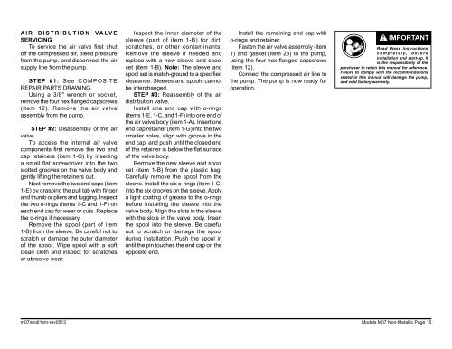
AIR DISTRIBUTION VALVESERVICINGTo service the air valve first shutoff the compressed air, bleed pressurefrom the pump, and disconnect the airsupply line from the pump.STEP #1: See COMPOSITEREPAIR PARTS DRAWING.Using a 3/8" wrench or socket,remove the four hex flanged capscrews(item 12). Remove the air valveassembly from the pump.STEP #2: Disassembly of the airvalve.To access the internal air valvecomponents first remove the two endcap retainers (item 1-G) by insertinga small flat screwdriver into the twoslotted grooves on the valve body andgently lifting the retainers out.Next remove the two end caps (item1-E) by grasping the pull tab with fingerand thumb or pliers and tugging. Inspectthe two o‐rings (items 1-C and 1-F) oneach end cap for wear or cuts. Replacethe o-rings if necessary.Remove the spool (part of item1-B) from the sleeve. Be careful not toscratch or damage the outer diameterof the spool. Wipe spool with a softclean cloth and inspect for scratchesor abrasive wear.Inspect the inner diameter of thesleeve (part of item 1-B) for dirt,scratches, or other contaminants.Remove the sleeve if needed andreplace with a new sleeve and spoolset (item 1-B). Note: The sleeve andspool set is match-ground to a specifiedclearance. Sleeves and spools cannotbe interchanged.STEP #3: Reassembly of the airdistribution valve.Install one end cap with o-rings(items 1-E, 1-C, and 1-F) into one end ofthe air valve body (item 1-A). Insert oneend cap retainer (item 1-G) into the twosmaller holes, align with groove in theend cap, and push until the closed endof the retainer is below the flat surfaceof the valve body.Remove the new sleeve and spoolset (item 1-B) from the plastic bag.Carefully remove the spool from thesleeve. Install the six o-rings (item 1-C)into the six grooves on the sleeve. Applya light coating of grease to the o-ringsbefore installing the sleeve into thevalve body. Align the slots in the sleevewith the slots in the valve body. Insertthe spool into the sleeve. Be carefulnot to scratch or damage the spoolduring installation. Push the spool inuntil the pin touches the end cap on theopposite end.Install the remaining end cap witho-rings and retainer.Fasten the air valve assembly (item1) and gasket (item 23) to the pump,using the four hex flanged capscrews(item 12).Connect the compressed air line tothe pump. The pump is now ready foroperation.IMPORTANTRead these instructionscompletely, beforeinstallation and start-up. Itis the responsibility of thepurchaser to retain this manual for reference.Failure to comply with the recommendationsstated in this manual will damage the pump,and void factory warranty.m07nmdl1sm-rev0513 Models M07 Non-Metallic Page 15