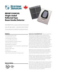
2451A Photoelectronic Plug-in Smoke Detectors - System Sensor ...
2451A Photoelectronic Plug-in Smoke Detectors - System Sensor ...
2451A Photoelectronic Plug-in Smoke Detectors - System Sensor ...

Create successful ePaper yourself
Turn your PDF publications into a flip-book with our unique Google optimized e-Paper software.
INSTALLATION AND MAINTENANCE INSTRUCTIONS<br />
<strong>2451A</strong> <strong>Photoelectronic</strong> <strong>Plug</strong>-<strong>in</strong><br />
<strong>Smoke</strong> <strong>Detectors</strong><br />
6581 Kitimat Rd., Unit #6, Mississauga, Ontario, L5N 3T5<br />
1-800-SENSOR2, FAX: 905-812-0771<br />
www.systemsensor.ca<br />
Specifications<br />
Size<br />
Height:<br />
2.4 <strong>in</strong>ches (61 mm)<br />
Add 0.5 <strong>in</strong>ches (13 cm) for thermal model 2451THA<br />
Diameter:<br />
4.0 <strong>in</strong>ches (101 cm)<br />
Weight: 0.5 lb. (277 g)<br />
Operat<strong>in</strong>g Temperature Range: 0° to 49°C (32° to 120°F)<br />
Operat<strong>in</strong>g Humidity Range: 10% to 93% Relative Humidity<br />
Maximum Air Velocity:<br />
3000 Ft./M<strong>in</strong>. (15 M/S)<br />
Lock<strong>in</strong>g Alarm:<br />
Reset by momentary power <strong>in</strong>terruption<br />
Fixed Temperature Thermal: 135°F (57°C)<br />
Before Install<strong>in</strong>g<br />
Please thoroughly read the <strong>System</strong> <strong>Sensor</strong> publication,<br />
I56-407, Applications Guide for <strong>System</strong> <strong>Smoke</strong> <strong>Detectors</strong>,<br />
which provides detailed <strong>in</strong>formation on detector spac<strong>in</strong>g,<br />
placement, zon<strong>in</strong>g, wir<strong>in</strong>g, and special applications. Copies<br />
of this guide are available at no charge from <strong>System</strong><br />
<strong>Sensor</strong>. Please also refer to CAN/ULC-S524, Standard<br />
for the Installation of Fire Alarm <strong>System</strong>s and CEC Part 1,<br />
Sec. 32..<br />
NOTICE: This manual should be left with the owner/user<br />
of this equipment.<br />
IMPORTANT: This sensor must be tested and ma<strong>in</strong>ta<strong>in</strong>ed<br />
regularly follow<strong>in</strong>g CAN/ULC-S536 requirements. This<br />
sensor should be cleaned at least once a year.<br />
General Description<br />
The <strong>2451A</strong> photoelectronic detector utilize state-of-the-art,<br />
optical sens<strong>in</strong>g chambers. This detector is designed to provide<br />
open area protection, and to be used with compatible<br />
ULC-listed control panels only. The capability of plugg<strong>in</strong>g<br />
this detector <strong>in</strong>to a variety of special bases makes it more<br />
versatile than equivalent direct-wired models.<br />
Two LEDs on each detector light to provide a local 360°<br />
visible alarm <strong>in</strong>dication. They flash every ten seconds <strong>in</strong>dicat<strong>in</strong>g<br />
that power is applied and the detector is operat<strong>in</strong>g<br />
properly. The LEDs light cont<strong>in</strong>uously <strong>in</strong> alarm. Remote<br />
LED annunciator capability is available as an optional ac-<br />
cessory. This detector also has the Latch<strong>in</strong>g Alarm feature.<br />
The alarm can be reset only by a momentary power <strong>in</strong>terruption.<br />
This detector may be tested by activat<strong>in</strong>g the <strong>in</strong>ternal<br />
reed switch with a magnet, or by <strong>in</strong>sert<strong>in</strong>g a calibrated<br />
test card <strong>in</strong> a test slot after remov<strong>in</strong>g the detector cover.<br />
Base Selection and Wir<strong>in</strong>g Guide<br />
Refer to the <strong>in</strong>stallation <strong>in</strong>structions for the <strong>Plug</strong>-<strong>in</strong> Detector<br />
Bases for base selection and wir<strong>in</strong>g <strong>in</strong>structions. <strong>System</strong><br />
<strong>Sensor</strong> has a variety of detector bases available for this<br />
smoke detector. This <strong>in</strong>cludes 2-wire applications with and<br />
without relays and/or current limit<strong>in</strong>g resistors, 4-wire and<br />
120VAC applications.<br />
All bases are provided with screw term<strong>in</strong>als for power,<br />
ground, remote annunciator connections and relay contact<br />
connections, if applicable. The electrical rat<strong>in</strong>gs for each<br />
detector-base comb<strong>in</strong>ation are also <strong>in</strong>cluded <strong>in</strong> the base<br />
<strong>in</strong>stallation <strong>in</strong>structions.<br />
Installation<br />
NOTE: Wir<strong>in</strong>g must conform to applicable local codes,<br />
ord<strong>in</strong>ances, and regulations.<br />
NOTE: Verify that all detector bases are <strong>in</strong>stalled, that the<br />
<strong>in</strong>itiat<strong>in</strong>g-device circuits have been tested, and<br />
that the wir<strong>in</strong>g is correct. (Refer to detector base<br />
manual for test<strong>in</strong>g procedure.)<br />
D400-02-01 REV#-002 1 I56-1020-000
Disconnect power from <strong>in</strong>itiat<strong>in</strong>g-device circuits before <strong>in</strong>stall<strong>in</strong>g<br />
detectors.<br />
1. Install detectors:<br />
a. Place the detector <strong>in</strong>to the detector base<br />
b. Turn the detector clockwise until the detector drops<br />
<strong>in</strong>to place.<br />
c. Cont<strong>in</strong>ue turn<strong>in</strong>g detector clockwise to lock it <strong>in</strong><br />
place.<br />
2. Tamper-proof Feature<br />
The detector bases <strong>in</strong>clude a feature that, when activated,<br />
prevents removal of the detector without the use<br />
of a tool. See the <strong>in</strong>stallation <strong>in</strong>struction manual of the<br />
detector base for details <strong>in</strong> us<strong>in</strong>g this feature.<br />
3. Afer all detectors have been <strong>in</strong>stalled, apply power to<br />
the control unit.<br />
4. Test the detector us<strong>in</strong>g the magnet or the test card as<br />
described under TESTING.<br />
Dust covers can be used to help limit dust entry to the<br />
detector, but they are not a substitute for remov<strong>in</strong>g the<br />
detector dur<strong>in</strong>g build<strong>in</strong>g construction. Remove any dust<br />
covers before plac<strong>in</strong>g system <strong>in</strong> service.<br />
Test<strong>in</strong>g<br />
Before test<strong>in</strong>g, notify the proper authorities that the smoke<br />
detector system is undergo<strong>in</strong>g ma<strong>in</strong>tenance and will temporarily<br />
be out of service. Disable the zone or system undergo<strong>in</strong>g<br />
ma<strong>in</strong>tenance to prevent unwanted alarms.<br />
<strong>Detectors</strong> must be tested after <strong>in</strong>stallation and periodic<br />
ma<strong>in</strong>tenance. To test the <strong>2451A</strong>:<br />
NOTE: Before test<strong>in</strong>g the detector, check to ensure that<br />
the LEDs are bl<strong>in</strong>k<strong>in</strong>g. If they are not, the detector<br />
has lost power (check the wir<strong>in</strong>g) or it is defective<br />
(return for repair).<br />
A. Test Magnet (<strong>System</strong> <strong>Sensor</strong> model no. M02-04-00)<br />
5. Reset the detector at the system control panel.<br />
6. Notify the proper authorities that the system is back on<br />
l<strong>in</strong>e.<br />
Figure 1. Bottom and side views show<strong>in</strong>g position of test magnet:<br />
LED<br />
TEST MODULE<br />
SOCKET<br />
TEST<br />
MAGNET<br />
PAINTED<br />
SURFACE<br />
TEST<br />
MAGNET<br />
LED<br />
A78-1213-00<br />
D400-02-01 REV#-002 2 I56-1020-000
1. Place the magnet aga<strong>in</strong>st the cover opposite the test<br />
module slot to activate the test feature (see Figure<br />
1).<br />
2. The LEDs should latch on with<strong>in</strong> 5 seconds <strong>in</strong>dicat<strong>in</strong>g<br />
alarm and annunciat<strong>in</strong>g the panel.<br />
<strong>Detectors</strong> that fail these tests should be cleaned as described<br />
under MAINTENANCE and retested. If the detectors<br />
still fail these tests they should be returned for repair.<br />
B. Calibrated Test Card (<strong>System</strong> <strong>Sensor</strong> no. R59-18-00)<br />
1. Remove the detector cover by plac<strong>in</strong>g a small bladed<br />
screwdriver <strong>in</strong> the side slot of the detector cover,<br />
twist<strong>in</strong>g it slightly until the cover can be turned counterclockwise<br />
for removal.<br />
2. Insert the NO ALARM end of the test card fully <strong>in</strong>to the<br />
test slot (see Figure 2) then slide it counterclockwise<br />
until it stops.<br />
3. Wait for at least 20 seconds. The detector should<br />
not alarm.<br />
4. Remove the test card by slid<strong>in</strong>g it clockwise before<br />
remov<strong>in</strong>g, then <strong>in</strong>sert the ALARM end.<br />
5. The LEDs should latch on with<strong>in</strong> 20 seconds <strong>in</strong>dicat<strong>in</strong>g<br />
alarm and annunciat<strong>in</strong>g the panel.<br />
6. Put the cover back by gently rotat<strong>in</strong>g it clockwise until<br />
it locks <strong>in</strong> place.<br />
C. Test Module (<strong>System</strong> <strong>Sensor</strong> no. MOD400R)<br />
The MOD400R is used with your DMM or voltmeter<br />
to check the detector sensitivity as described <strong>in</strong> the<br />
MOD400R’s manual.<br />
D. Aerosol Generator (Gem<strong>in</strong>i 501)<br />
Set the generator to represent 4% to 5%/Ft. obscuration<br />
as described <strong>in</strong> the Gem<strong>in</strong>i 501 Manual. Us<strong>in</strong>g the bowl<br />
shaped applicator, apply aerosol until the unit alarms.<br />
Figure 2:<br />
TEST SLOT<br />
HEAD COVER<br />
REMOVAL SLOT<br />
REMOVABLE HEAD COVER<br />
CLEANABLE SCREEN<br />
P/N RS24 (W/O THERMAL)<br />
VANED CHAMBER<br />
A78-1213-01<br />
Notify the proper authorities that the detection system is<br />
back on l<strong>in</strong>e.<br />
Ma<strong>in</strong>tenance<br />
It is recommended that the detector be removed from its<br />
mount<strong>in</strong>g base to facilitate easier clean<strong>in</strong>g. The detector is<br />
cleaned as follows:<br />
NOTE: Before remov<strong>in</strong>g the detector, notify the proper<br />
authorities that the smoke detector system is undergo<strong>in</strong>g<br />
ma<strong>in</strong>tenance and will temporarily be out<br />
of service. Disable the zone or system undergo<strong>in</strong>g<br />
ma<strong>in</strong>tenance to prevent unwanted alarms.<br />
1. Remove the detector cover by plac<strong>in</strong>g a small bladed<br />
screwdriver <strong>in</strong> the side slot of the detector cover, twist<strong>in</strong>g<br />
it slightly until the cover can be turned counterclockwise<br />
for removal.<br />
D400-02-01 REV#-002 3 I56-1020-000
2. Vacuum the screen carefully without remov<strong>in</strong>g it. If further<br />
clean<strong>in</strong>g is required cont<strong>in</strong>ue with Step 3, otherwise<br />
skip to Step 6.<br />
3. Remove the screen by pull<strong>in</strong>g it straight out (see Figure<br />
2). Vacuum the <strong>in</strong>side.<br />
4. Clean the vaned chamber piece by vacuum<strong>in</strong>g or blow<strong>in</strong>g<br />
out dust and particles.<br />
5. To replace the screen, orient it so that the arrow on top<br />
aligns with the test module socket of the detector. Carefully<br />
push the screen onto the base mak<strong>in</strong>g sure it fits<br />
tightly to the chamber.<br />
6. Replace the cover by gently rotat<strong>in</strong>g it clockwise until it<br />
locks <strong>in</strong> place.<br />
7. Re<strong>in</strong>stall the detector.<br />
8. Notify the proper authorities that the system is back on<br />
l<strong>in</strong>e.<br />
Please refer to <strong>in</strong>sert for the Limitations of Fire Alarm <strong>System</strong>s<br />
<strong>System</strong> <strong>Sensor</strong> warrants its enclosed smoke detector to be free from defects <strong>in</strong> materials<br />
and workmanship under normal use and service for a period of three years<br />
from date of manufacture. <strong>System</strong> <strong>Sensor</strong> makes no other express warranty for this<br />
smoke detector. No agent, representative, dealer, or employee of the Company has<br />
the authority to <strong>in</strong>crease or alter the obligations or limitations of this Warranty. The<br />
Company’s obligation of this Warranty shall be limited to the repair or replacement<br />
of any part of the smoke detector which is found to be defective <strong>in</strong> materials or workmanship<br />
under normal use and service dur<strong>in</strong>g the three year period commenc<strong>in</strong>g<br />
with the date of manufacture. After phon<strong>in</strong>g <strong>System</strong> <strong>Sensor</strong>’s toll free number 1-<br />
800-SENSOR2 (736-7672) for a Return Authorization number, send defective units<br />
postage prepaid to: <strong>System</strong> <strong>Sensor</strong>, Repair Department, RA #__________, 6581<br />
Three-Year Limited Warranty<br />
Kitimat Rd., Unit #6, Mississauga, Ontario, L5N 3T5. Please <strong>in</strong>clude a note describ<strong>in</strong>g<br />
the malfunction and suspected cause of failure. The Company shall not be obligated<br />
to repair or replace units which are found to be defective because of damage,<br />
unreasonable use, modifications, or alterations occurr<strong>in</strong>g after the date of manufacture.<br />
In no case shall the Company be liable for any consequential or <strong>in</strong>cidental<br />
damages for breach of this or any other Warranty, expressed or implied whatsoever,<br />
even if the loss or damage is caused by the Company’s negligence or fault. Some<br />
states do not allow the exclusion or limitation of <strong>in</strong>cidental or consequential damages,<br />
so the above limitation or exclusion may not apply to you. This Warranty gives<br />
you specific legal rights, and you may also have other rights under common law.<br />
D400-02-01 REV#-002 4 I56-1020-000<br />
© <strong>System</strong> <strong>Sensor</strong> 2004