2451A Photoelectronic Plug-in Smoke Detectors - System Sensor ...
2451A Photoelectronic Plug-in Smoke Detectors - System Sensor ...
2451A Photoelectronic Plug-in Smoke Detectors - System Sensor ...

Create successful ePaper yourself
Turn your PDF publications into a flip-book with our unique Google optimized e-Paper software.
1. Place the magnet aga<strong>in</strong>st the cover opposite the test<br />
module slot to activate the test feature (see Figure<br />
1).<br />
2. The LEDs should latch on with<strong>in</strong> 5 seconds <strong>in</strong>dicat<strong>in</strong>g<br />
alarm and annunciat<strong>in</strong>g the panel.<br />
<strong>Detectors</strong> that fail these tests should be cleaned as described<br />
under MAINTENANCE and retested. If the detectors<br />
still fail these tests they should be returned for repair.<br />
B. Calibrated Test Card (<strong>System</strong> <strong>Sensor</strong> no. R59-18-00)<br />
1. Remove the detector cover by plac<strong>in</strong>g a small bladed<br />
screwdriver <strong>in</strong> the side slot of the detector cover,<br />
twist<strong>in</strong>g it slightly until the cover can be turned counterclockwise<br />
for removal.<br />
2. Insert the NO ALARM end of the test card fully <strong>in</strong>to the<br />
test slot (see Figure 2) then slide it counterclockwise<br />
until it stops.<br />
3. Wait for at least 20 seconds. The detector should<br />
not alarm.<br />
4. Remove the test card by slid<strong>in</strong>g it clockwise before<br />
remov<strong>in</strong>g, then <strong>in</strong>sert the ALARM end.<br />
5. The LEDs should latch on with<strong>in</strong> 20 seconds <strong>in</strong>dicat<strong>in</strong>g<br />
alarm and annunciat<strong>in</strong>g the panel.<br />
6. Put the cover back by gently rotat<strong>in</strong>g it clockwise until<br />
it locks <strong>in</strong> place.<br />
C. Test Module (<strong>System</strong> <strong>Sensor</strong> no. MOD400R)<br />
The MOD400R is used with your DMM or voltmeter<br />
to check the detector sensitivity as described <strong>in</strong> the<br />
MOD400R’s manual.<br />
D. Aerosol Generator (Gem<strong>in</strong>i 501)<br />
Set the generator to represent 4% to 5%/Ft. obscuration<br />
as described <strong>in</strong> the Gem<strong>in</strong>i 501 Manual. Us<strong>in</strong>g the bowl<br />
shaped applicator, apply aerosol until the unit alarms.<br />
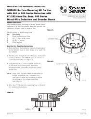
Figure 2:<br />
TEST SLOT<br />
HEAD COVER<br />
REMOVAL SLOT<br />
REMOVABLE HEAD COVER<br />
CLEANABLE SCREEN<br />
P/N RS24 (W/O THERMAL)<br />
VANED CHAMBER<br />
A78-1213-01<br />
Notify the proper authorities that the detection system is<br />
back on l<strong>in</strong>e.<br />
Ma<strong>in</strong>tenance<br />
It is recommended that the detector be removed from its<br />
mount<strong>in</strong>g base to facilitate easier clean<strong>in</strong>g. The detector is<br />
cleaned as follows:<br />
NOTE: Before remov<strong>in</strong>g the detector, notify the proper<br />
authorities that the smoke detector system is undergo<strong>in</strong>g<br />
ma<strong>in</strong>tenance and will temporarily be out<br />
of service. Disable the zone or system undergo<strong>in</strong>g<br />
ma<strong>in</strong>tenance to prevent unwanted alarms.<br />
1. Remove the detector cover by plac<strong>in</strong>g a small bladed<br />
screwdriver <strong>in</strong> the side slot of the detector cover, twist<strong>in</strong>g<br />
it slightly until the cover can be turned counterclockwise<br />
for removal.<br />
D400-02-01 REV#-002 3 I56-1020-000