
You also want an ePaper? Increase the reach of your titles
YUMPU automatically turns print PDFs into web optimized ePapers that Google loves.
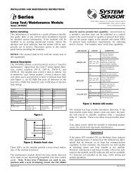
INSTALLATION AND MAINTENANCE INSTRUCTIONS<br />
D4120 Duct Smoke Detector<br />
D4S Sensor Component<br />
D4P120 Power Board Component<br />
3825 Ohio Avenue, St. Charles, Illinois 60174<br />
1-800-SENSOR2, FAX: 630-377-6495<br />
www.systemsensor.com<br />
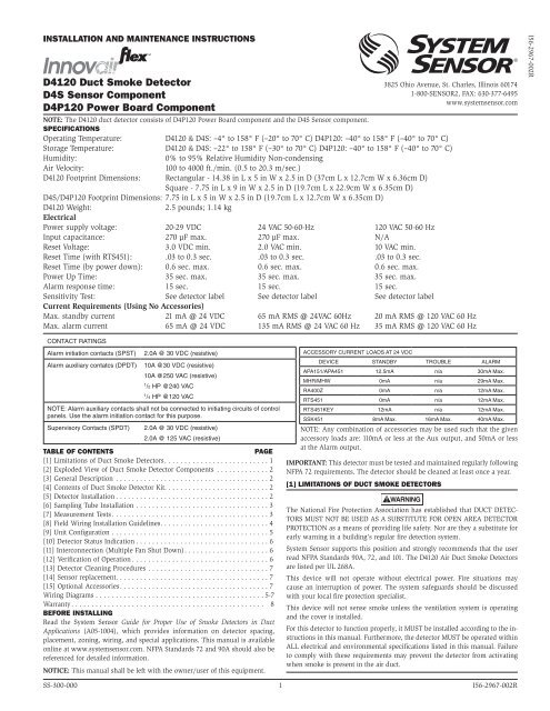
NOTE: The D4120 duct detector consists of D4P120 Power Board component and the D4S Sensor component.<br />
Specifications<br />
Operating Temperature: D4120 & D4S: –4° to 158° F (–20° to 70° C) D4P120: –40° to 158° F (–40° to 70° C)<br />
Storage Temperature: D4120 & D4S: –22° to 158° F (–30° to 70° C) D4P120: –40° to 158° F (–40° to 70° C)<br />
Humidity:<br />
0% to 95% Relative Humidity Non-condensing<br />
Air Velocity:<br />
100 to 4000 ft./min. (0.5 to 20.3 m/sec.)<br />
D4120 Footprint Dimensions: Rectangular - 14.38 in L x 5 in W x 2.5 in D (37cm L x 12.7cm W x 6.36cm D)<br />
Square - 7.75 in L x 9 in W x 2.5 in D (19.7cm L x 22.9cm W x 6.35cm D)<br />
D4S/D4P120 Footprint Dimensions: 7.75 in L x 5 in W x 2.5 in D (19.7cm L x 12.7cm W x 6.35cm D)<br />
D4120 Weight:<br />
2.5 pounds; 1.14 kg<br />
Electrical<br />
Power supply voltage: 20-29 VDC 24 VAC 50-60-Hz 120 VAC 50-60 Hz<br />
Input capacitance: 270 µF max. 270 µF max. N/A<br />
Reset Voltage: 3.0 VDC min. 2.0 VAC min. 10 VAC min.<br />
Reset Time (with RTS451): .03 to 0.3 sec. .03 to 0.3 sec. .03 to 0.3 sec.<br />
Reset Time (by power down): 0.6 sec. max. 0.6 sec. max. 0.6 sec. max.<br />
Power Up Time: 35 sec. max. 35 sec. max. 35 sec. max.<br />
Alarm response time: 15 sec. 15 sec. 15 sec.<br />
Sensitivity Test: See detector label See detector label See detector label<br />
Current Requirements (Using No Accessories)<br />
Max. standby current 21 mA @ 24 VDC 65 mA RMS @ 24VAC 60Hz 20 mA RMS @ 120 VAC 60 Hz<br />
Max. alarm current 65 mA @ 24 VDC 135 mA RMS @ 24 VAC 60 Hz 35 mA RMS @ 120 VAC 60 Hz<br />
<strong>I56</strong>-<strong>2967</strong>-<strong>002R</strong><br />
CONTACT RATINGS<br />
Alarm initiation contacts (SPST)<br />
Alarm auxiliary contatcs (DPDT)<br />
2.0A @ 30 VDC (resistive)<br />
10A @30 VDC (resistive)<br />
10A @250 VAC (resistive)<br />
1<br />
/2 HP @240 VAC<br />
1<br />
/4 HP @120 VAC<br />
NOTE: Alarm auxiliary contacts shall not be connected to initiating circuits of control<br />
panels. Use the alarm initiation contact for this purpose.<br />
Supervisory Contacts (SPDT) 2.0A @ 30 VDC (resistive)<br />
2.0A @ 125 VAC (resistive)<br />
Table of Contents<br />
Page<br />
[1] Limitations of Duct Smoke Detectors. . . . . . . . . . . . . . . . . . . . . . . . . . 1<br />
[2] Exploded View of Duct Smoke Detector Components .............2<br />
[3] General Description ......................................2<br />
[4] Contents of Duct Smoke Detector Kit. . . . . . . . . . . . . . . . . . . . . . . . . . 2<br />
[5] Detector Installation . . . . . . . . . . . . . . . . . . . . . . . . . . . . . . . . . . . . . . 2<br />
[6] Sampling Tube Installation .................................3<br />
[7] Measurement Tests. . . . . . . . . . . . . . . . . . . . . . . . . . . . . . . . . . . . . . . 3<br />
[8] Field Wiring Installation Guidelines. . . . . . . . . . . . . . . . . . . . . . . . . . . 4<br />
[9] Unit Configuration .......................................5<br />
[10] Detector Status Indication . . . . . . . . . . . . . . . . . . . . . . . . . . . . . . . . . 6<br />
[11] Interconnection (Multiple Fan Shut Down). . . . . . . . . . . . . . . . . . . . . 6<br />
[12] Verification of Operation . . . . . . . . . . . . . . . . . . . . . . . . . . . . . . . . . . 6<br />
[13] Detector Cleaning Procedures ..............................7<br />
[14] Sensor replacement. . . . . . . . . . . . . . . . . . . . . . . . . . . . . . . . . . . . . . 7<br />
[15] Optional Accessories. . . . . . . . . . . . . . . . . . . . . . . . . . . . . . . . . . . . . 7<br />
Wiring Diagrams . . . . . . . . . . . . . . . . . . . . . . . . . . . . . . . . . . . . . . . . . . 5-7<br />
Warranty . . . . . . . . . . . . . . . . . . . . . . . . . . . . . . . . . . . . . . . . . . . . . . . . 8<br />
Before Installing<br />
Read the System Sensor Guide for Proper Use of Smoke Detectors in Duct<br />
Applications (A05-1004), which provides information on detector spacing,<br />
placement, zoning, wiring, and special applications. This manual is available<br />
online at www.systemsensor.com. NFPA Standards 72 and 90A should also be<br />
referenced for detailed information.<br />
NOTICE: This manual shall be left with the owner/user of this equipment.<br />
ACCESSORY CURRENT LOADS AT 24 VDC<br />
DEVICE STANDBY TROUBLE ALARM<br />
APA151/APA451 12.5mA n/a 30mA Max.<br />
MHR/MHW 0mA n/a 29mA Max.<br />
RA400Z 0mA n/a 12mA Max.<br />
RTS451 0mA n/a 12mA Max.<br />
RTS451KEY 12mA n/a 12mA Max.<br />
SSK451 8mA Max. 16mA Max. 40mA Max.<br />
NOTE: Any combination of accessories may be used such that the given<br />
accessory loads are: 110mA or less at the Aux output, and 50mA or less<br />
at the Alarm output.<br />
IMPORTANT: This detector must be tested and maintained regularly following<br />
NFPA 72 requirements. The detector should be cleaned at least once a year.<br />
[1] Limitations Of Duct Smoke Detectors<br />
WARNING<br />
The National <strong>Fire</strong> Protection Association has established that DUCT DETEC-<br />
TORS MUST NOT BE USED AS A SUBSTITUTE FOR OPEN AREA DETECTOR<br />
PROTECTION as a means of providing life safety. Nor are they a substitute for<br />
early warning in a building’s regular fire detection system.<br />
System Sensor supports this position and strongly recommends that the user<br />
read NFPA Standards 90A, 72, and 101. The D4120 Air Duct Smoke Detectors<br />
are listed per UL 268A.<br />
This device will not operate without electrical power. <strong>Fire</strong> situations may<br />
cause an interruption of power. The system safeguards should be discussed<br />
with your local fire protection specialist.<br />
This device will not sense smoke unless the ventilation system is operating<br />
and the cover is installed.<br />
For this detector to function properly, it MUST be installed according to the instructions<br />
in this manual. Furthermore, the detector MUST be operated within<br />
ALL electrical and environmental specifications listed in this manual. Failure<br />
to comply with these requirements may prevent the detector from activating<br />
when smoke is present in the air duct.<br />
SS-300-000 1 <strong>I56</strong>-<strong>2967</strong>-<strong>002R</strong>
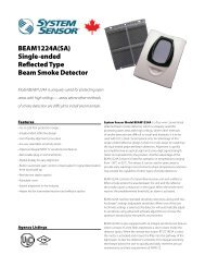
[2] Figure 1. Exploded View of Duct Smoke Detector Components:<br />
EXHAUST TUBE<br />
POWER BOARD<br />
4-WIRE<br />
POWER BOARD MODULE COVER<br />
SENSOR MODULE<br />
COVER<br />
METAL<br />
SAMPLING TUBE<br />
(sold seperately)<br />
SENSOR HEAD<br />
MAGNET TEST LOCATION<br />
H0549-01<br />
[3] General Description<br />
Smoke introduced into an air duct system will be distributed throughout the<br />
entire building. Smoke detectors designed for use in air duct systems are used<br />
to sense the presence of smoke in the duct.<br />
Model D4120 and D4S Duct Smoke Detectors utilize 4-wire photoelectric technology<br />
for the detection of smoke. This detection method, when combined<br />
with an efficient housing, samples air passing through the duct allowing detection<br />
of a developing hazardous condition. When sufficient smoke is sensed,<br />
an alarm signal is initiated and appropriate action can be taken to shut off<br />
fans, blowers, change over air handling systems, etc. These actions can facilitate<br />
the management of toxic smoke and fire gases throughout the areas<br />
served by the duct system.<br />
The D4120 and D4P120 detectors are designed to operate on 24 VDC/VAC or<br />
120 VAC. Alarm and supervisory relay contacts are available for control panel<br />
interface (alarm initiation), HVAC control, and other auxiliary functions. Auxiliary<br />
relays are provided for fan shut down. Detector interconnection provides<br />
signaling of up to 50 other detectors in the loop for multiple fan shut down.<br />
These detectors are not designed for 2-wire applications.<br />
[3.1] Detector Feature Set<br />
-Utilizes 2D51 plug-in head<br />
-2 sensors to 1 power board capability<br />
-Cover missing signal<br />
-Sampling tubes install from front or rear of detector<br />
-Compatible with existing accessories<br />
[4] Contents Of The Duct Smoke Detector Kit<br />
1. Sensor/power board assembly and cover(s)<br />
2. Three #10 sheet metal screws for mounting<br />
3. One test magnet<br />
4. Drilling template<br />
5. One sampling tube end cap<br />
6. One plastic exhaust tube<br />
NOTE: A sampling tube must be ordered to complete the installation. It must<br />
be the correct length for the width of the duct where it will be installed.<br />
See Table 1 on page 3 to determine the inlet tube required for different duct<br />
widths.<br />
[5] Detector Installation<br />
[5.1] Verify Air Flow Direction And Velocity<br />
Model D4120 detectors are designed to be used in air handling systems with<br />
air velocities of 100 to 4000 feet per minute. Duct widths from 6 inches to 12<br />
feet can be accommodated. Be sure to check engineering specifications to<br />
ensure that the air velocity in the duct falls within these parameters. If necessary,<br />
use a velocity meter (anemometer) to check the air velocity in the duct.<br />
[5.2] Determine Mounting location and Configuration<br />
On ducts wider than 18 inches it is recommended that the detector be<br />
mounted downstream of a bend, obstruction in the duct, or the supply or<br />
return air inlet.<br />
Exception: Installation of duct detectors can be on or within a commercial<br />
packaged rooftop heating and air-conditioning system, fire/smoke dampers<br />
and economizers. They may be mounted in either the supply and/or return air<br />
section as determined by local code.<br />
Once a suitable location is selected, determine if the detector is to be mounted<br />
in a side-by-side “rectangular” configuration or a top-over-bottom “square”<br />
configuration as shown in Figure 2. If mounting in the square configuration,<br />
remove the rear attachment screw, rotate the unit at the hinge, and replace the<br />
screw into the new attachment hole as shown in Figure 2. Do NOT remove<br />
the hinge screw during this process. Final installation approval shall be based<br />
upon passing section 7.2.2 and/or 8.2.4 tests.<br />
Figure 2:<br />
REMOVE SCREW AND PIVOT<br />
DETECTOR AS SHOWN BELOW.<br />
REPLACE SCREW<br />
TO SECURE DETECTOR<br />
IN PLACE.<br />
H0550-00<br />
[5.3] Drill the Mounting Holes<br />
Remove the paper backing from the mounting template supplied. Affix the<br />
template to the duct at the desired mounting location. Make sure the template<br />
lies flat and smooth on the duct.<br />
[5.3.1] For rectangular side-by-side mounting configuration:<br />
Center punch at (4) target centers: (2) “A” for sampling tubes and (2) “B” for<br />
the rectangular configuration mounting tabs as shown on mounting template.<br />
Drill pilot holes at target “A” centers and cut two 1.375 inch diameter holes<br />
using a 1 3 /8 inch hole saw or punch. Drill .156 inch diameter holes using a 5 /32<br />
inch drill at target “B” centers.<br />
SS-300-000 2 <strong>I56</strong>-<strong>2967</strong>-<strong>002R</strong>
[5.3.2] For square top-over-bottom mounting<br />
configuration or D4S sensor component mounting:<br />
Center punch at (4) target centers: (2) “A” for sampling tubes and (2) “C” for<br />
the square configuration mounting tabs as shown on mounting template. Drill<br />
pilot holes at target “A” centers and cut two 1.375 inch diameter holes using<br />
a 1 3 /8 inch hole saw or punch. Drill .156 inch diameter holes using a 5 /32 inch<br />
drill at target “C” centers. If desired, drill an additional .156 inch hole at the<br />
location of one of the mounting tabs on the lower housing.<br />
[5.4] Secure the Duct Detector to the Duct<br />
Use two (rectangular configuration) or three (square configuration) of the provided<br />
sheet metal screws to screw the duct detector to the duct.<br />
CAUTION: Do not overtighten the screws.<br />
[6] Sampling Tube Installation<br />
[6.1] Sampling Tube Selection<br />
The sampling tube must be purchased separately. Order the correct length,<br />
as specified in Table 1, for width of the duct where it will be installed. It is<br />
recommended that the sampling tube length extend at least 2 /3 across the duct<br />
width for optimal performance.<br />
Table 1. Sampling tubes recommended for different<br />
duct widths:<br />
Outside Duct Width<br />
Up to 1 ft.<br />
Sampling Tube Recommended*<br />
DST1<br />
1 to 2 ft. DST1.5<br />
2 to 4 ft. DST3<br />
4 to 8 ft. DST5<br />
8 to 12 ft. DST10 (2-piece)<br />
*Must extend a minimum of 2 /3 the duct width. These sampling tubes can<br />
only be used with new InnovairFlex duct smoke detectors.<br />
The sampling tube is always installed with the air inlet holes facing into the<br />
air flow. To assist proper installation, the tube’s connector is marked with an<br />
arrow. Make sure the sampling tube is mounted so that the arrow points into<br />
the airflow as shown in Figure 3. Mounting the detector housing in a vertical<br />
orientation is acceptable provided that the air flows directly into the sampling<br />
tube holes as indicated in Figure 3. The sampling tube and exhaust tube<br />
can be mounted in either housing connection as long as the exhaust tube is<br />
mounted downstream from the sampling tube.<br />
Figure 3. Air duct detector sampling tube:<br />
SAMPLING TUBE ENDCAP<br />
ARROW MUST FACE<br />
INTO AIR FLOW<br />
AIR FLOW<br />
DIRECTION<br />
H0551-00<br />
CAUTION: The sampling tube end cap, included with the detector, is critical<br />
to proper operation of the duct smoke detector. The end cap is needed to<br />
create the proper air flow to the sensor of the duct smoke detector. Once any<br />
sampling tube length adjustments are made, plug the end of the sampling tube<br />
with the provided end cap.<br />
A plastic exhaust tube is included with the unit to be installed if needed. Install<br />
into the housing connection that is downstream from the sampling tube<br />
connection. The exhaust tube can be installed from the front or back of the<br />
detector. A longer 1 foot exhaust tube, model ETX, is available as an accessory<br />
in cases where the molded exhaust tube does not extend at least 2 inches into<br />
the duct.<br />
[6.2] Sampling Tube Installation<br />
1. For tubes shorter than the width of the duct, slide the sampling tube,<br />
with installed end cap, into the housing connection that meets the airflow<br />
first. Position the tube so the arrow points into the airflow as shown<br />
in Figure 3. Per NFPA sampling tubes over 3 feet long should be supported<br />
at the end opposite the duct detector. In ducts wider than 8 feet,<br />
work must be performed inside the duct to couple the other section of<br />
the sampling tube to the section already installed using the 1 /2 inch conduit<br />
fitting. Make sure that the holes on both sections of the air inlet<br />
sampling tube are lined up and facing into the airflow.<br />
2. For tubes longer than the width of the duct, the tube should extend out<br />
of the opposite side of the duct. Drill a 3 /4 inch hole in the duct opposite<br />
the hole already cut for the sampling tube. Ensure that the sampling tube<br />
is angled downward from the duct smoke detector to allow for moisture<br />
drainage away from the detector. The sampling tube should be angled<br />
at least 1/4” downward for every 12” of duct width per Figure 4. There<br />
should be 10 to 12 holes spaced as evenly as possible across the width of<br />
the duct. If there are more than 2 holes in the section of the tube extending<br />
out of the duct, select a shorter tube using Table 1. Otherwise, trim<br />
the tube to leave approximately 1 to 2 inches extending outside the duct.<br />
Plug the end with the end cap and tape closed any holes in the protruding<br />
section of tube. Be sure to seal the duct where the tube protrudes.<br />
Figure 4.<br />
2˝<br />
3<br />
/4˝<br />
HOLE<br />
1<br />
/ 4˝<br />
12˝<br />
DETECTOR<br />
H0215-00<br />
NOTE: Air currents inside the duct may cause excessive vibration, especially<br />
when the longer sampling tubes are used. In these cases, a 3 inch floor flange<br />
(available at most plumbing supply stores) may be used to fasten the sampling<br />
tube to the other side of the duct. When using the flange/connector mounting<br />
technique, drill a 1 to 1 /4 inch hole where the flange will be used.<br />
[6.3] Modifications of Sampling Tubes<br />
There may be applications where duct widths are not what is specified for the<br />
installation. In such cases, it is permissible to modify a sampling tube that is<br />
longer than necessary to span the duct width.<br />
Use a 0.193 inch diameter (#10) drill and add the appropriate number of holes<br />
so that the total number of holes exposed to the air flow in the duct is 10 to 12.<br />
Space the additional holes as evenly as possible over the length of the tube.<br />
NOTE: This procedure should only be used as a temporary fix and is not intended<br />
as a substitute for ordering the correct length tubes.<br />
[6.4] Remote Sampling Tube Installation<br />
The detector arrangement can also incorporate remote mounting of the sampling<br />
tube and/or exhaust tube. In this case both the detector, sampling tube<br />
and exhaust tube (if included) should be rigidly mounted to withstand the<br />
pressure and vibrations caused by the air velocity. The location of the detector’s<br />
sampling tube should be such that there is uniform airflow in the cross<br />
section area.<br />
The pressure differential across the sampling and exhaust ports in the detector<br />
housing shall be verified to be between 0.01 and 1.11 inches of water. Do so<br />
by measuring the pressure difference between the inlet and outlet ports on the<br />
detector housing using a manometer as described in Section 7.1.<br />
[7] Measurement tests<br />
[7.1] air flow<br />
The D4120 is designed to operate over an extended air speed range of 100 to<br />
4000 FPM. To verify sufficient sampling of ducted air, turn the air handler on<br />
and use a manometer to measure the differential pressure between the two<br />
sampling tubes. The differential pressure should measure at least 0.01 inches<br />
of water and no more than 1.11 inches of water. Because most commercially<br />
available manometers cannot accurately measure very low pressure differentials,<br />
applications with less than 500 FPM of air speed may require one of the<br />
following: 1) the use of a current-sourcing pressure transmitter (Dwyer Series<br />
607) per Section 7.2, or 2) the use of aerosol smoke per section 12.5.3.<br />
SS-300-000 3 <strong>I56</strong>-<strong>2967</strong>-<strong>002R</strong>
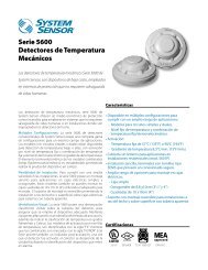
[7.2] Low Flow Air Flow Test using Dwyer Series 607<br />
Differential Pressure Transmitter<br />
Verify the air speed of the duct using an anemometer. Air speed must be at<br />
least 100 FPM. Wire the Dwyer transmitter as shown in Figure 5. Connect the<br />
leads of the meter to either side of the 1000Ω resistor. Allow unit to warm up<br />
for 15 seconds. With both HIGH and LOW pressure ports open to ambient air,<br />
measure and record the voltage drop across the 1000Ω resistor (measurement<br />
1), 4.00 volts is typical. Using flexible tubing and rubber stoppers, connect the<br />
HIGH side of the transmitter to the sampling tube of the duct smoke detector<br />
housing, and the LOW side of the transmitter to the exhaust tube of the<br />
duct smoke detector housing. Measure and record the voltage drop across the<br />
1000Ω resistor (measurement 2). Subtract the voltage recorded in measurement<br />
1 from the voltage recorded in measurement 2. If the difference is greater<br />
than 0.15 volts, there is enough air flow through the duct smoke detector for<br />
proper operation.<br />
Figure 5. Procedure for verifying air flow less than 500 FPM:<br />
HIGH<br />
LOW<br />
DIFFERENTIAL<br />
PRESSURE<br />
TRANSMITTER<br />
MODEL #607-01<br />
1000 OHM 5%<br />
1 WATT RESISTOR<br />
VOLT METER FLUKE<br />
MODEL 87 OR<br />
EQUIVALENT<br />
+ –<br />
TO SAMPLING TUBE<br />
TO EXHAUST TUBE<br />
15 TO 36<br />
VDC SUPPLY<br />
9 VOLT<br />
BATTERY<br />
9 VOLT<br />
BATTERY<br />
9 VOLT<br />
BATTERY<br />
[8] field wiring installation Guidelines<br />
All wiring must be installed in compliance with the National Electrical Code<br />
and the local codes having jurisdiction. Proper wire gauges should be used.<br />
The conductors used to connect smoke detectors to control panels and accessory<br />
devices should be color-coded to prevent wiring mistakes. Improper connections<br />
can prevent a system from responding properly in the event of a fire.<br />
For signal wiring, (wiring between interconnected detectors or from detectors<br />
to auxiliary devices), it is recommended that single conductor wire be no<br />
smaller than 18 gauge.<br />
Smoke detectors and alarm system control panels have specifications for allowable<br />
loop resistance. Consult the control panel manufacturer’s specifications<br />
for the total loop resistance allowed for the particular control panel being<br />
used before wiring the detector loop.<br />
[8.1] Wiring Instructions<br />
The D4120 and D4P120 detectors are designed for easy wiring. The housing<br />
provides a terminal strip with clamping plates. The D4S housing provides 4<br />
wiring terminals with clamping plates. Wiring connections are made by sliding<br />
the bare end of the wire under the plate, and tightening the clamping plate<br />
screw. See Figure 7 on page 5 for system wiring.<br />
[8.2] Sensor 2 Installation/Wiring<br />
The power board is capable of controlling a second housed sensor. The second<br />
sensor, model D4S, can be wired to the power board per the following:<br />
1. Connect wires to the four wire terminals in the corner of the D4S sensor<br />
housing designated as Tamper (Y,Y), +R, and –B. Route wires through the<br />
conduit openings in the sensor housing and D4120 power board housing.<br />
2. Connect the opposing ends of the wires to the terminal connections<br />
marked “Sensor 2” on the Power board. See Figure 6 for reference. Ensure<br />
that wires are connected to the appropriate terminal locations. A<br />
No. 0 or 1 phillips screwdriver should be used for terminal connection.<br />
The tamper terminals are not polarity sensitive.<br />
3. Adjust the middle dip switch on the power board to indicate (2) sensors<br />
as shown in Figure 6.<br />
4. The D4S can only be used with new InnovairFlex models and is not compatible<br />
with previously sold detectors.<br />
H0163-01<br />
Figure 6. Optional sensor 2 configuration and wiring:<br />
D4S<br />
SENSOR ONLY<br />
NOTE: IF USING (2) D4S<br />
SENSOR ONLY<br />
COMPONENTS WITH<br />
MODEL D4P120 POWER<br />
BOARD COMPONENT, USE<br />
SENSOR #1 TERMINALS<br />
AND WIRE IN SAME<br />
MANNER AS SHOWN FOR<br />
SENSOR #2.<br />
WIRING TERMINALS<br />
D4S<br />
TAMPER + –<br />
Y Y R B<br />
D4120<br />
CO-LOCATED<br />
FIELD SELECTABLE<br />
DIP SWITCHES<br />
SENSOR #1<br />
TERMINALS<br />
SENSOR #2<br />
TERMINALS<br />
GROUND<br />
SCREW<br />
OFF/ON TRBL SHUTDN<br />
1/2 SENSORS<br />
7/0 MIN TMPR DELAY<br />
Y Y R Ḇ Y Y R<br />
TAMPER + TAMPER +<br />
SENSOR 1 SENSOR 2<br />
ACC -<br />
ACC +<br />
R RESET, 2<br />
R TEST, 11<br />
Ḇ<br />
ALARM, 15<br />
INT+, 12<br />
INT/AUX-, 1<br />
AUX OUT -, 20<br />
AUX OUT +, 19<br />
24V AC/DC, 9<br />
24V AC/DC, 10<br />
120 VAC<br />
Y Y R B<br />
TAMPER + –<br />
SENSOR 2<br />
D4120<br />
SENSOR<br />
LEDs<br />
POWER<br />
BOARD LED 2<br />
POWER<br />
BOARD LED 1<br />
4, C<br />
5, NO<br />
ALARM<br />
13, NC<br />
3, C<br />
SUP<br />
14, N0<br />
16, NC<br />
TEST/RESET<br />
BUTTON<br />
6, C<br />
AUX A<br />
17, NO<br />
8, NC<br />
18, C<br />
AUX B<br />
7, NO<br />
120<br />
VAC INPUT<br />
24 VAC/<br />
DC INPUT<br />
H0557-01<br />
SS-300-000 4 <strong>I56</strong>-<strong>2967</strong>-<strong>002R</strong>
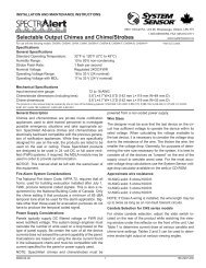
Figure 7. System wiring diagram for 4-wire duct smoke detectors:<br />
CAUTION<br />
Do not loop wire under terminals when wiring detectors. Break wire runs to provide system supervision of connections.<br />
POWER INPUTS (NOTE 1) POWER INPUTS (NOTE 1)<br />
24VAC/DC<br />
120<br />
VAC<br />
24V<br />
120<br />
VAC<br />
9 10<br />
9 10<br />
OR<br />
AUXILIARY CONTACTS<br />
FOR FAN SHUTDOWN, ETC. (NOTE 2)<br />
AUX A<br />
AUX B<br />
N.C. C. N.O. N.C. C. N.O.<br />
AUXILIARY CONTACTS<br />
FOR FAN SHUTDOWN, ETC. (NOTE 2)<br />
N.C.<br />
AUX A<br />
C.<br />
N.O.<br />
OR<br />
AUX B<br />
N.C. C.<br />
N.O.<br />
16 6 17 8 18 7<br />
16 6 17 8 18 7<br />
SUPERVISORY CONTACTS<br />
(NOTE 3)<br />
SUPERVISORY CONTACTS<br />
(NOTE 3)<br />
SUP C. SUP N.O. SUP C.<br />
SUP N.O.<br />
EOL RESISTOR<br />
SPECIFIED BY<br />
PANEL<br />
MANUFACTURER<br />
UL/FM LISTED<br />
4-WIRE<br />
CONTROL PANEL<br />
+<br />
3 14 3<br />
14<br />
ALARM<br />
INITIATION<br />
LOOP<br />
ALARM<br />
INITIATION<br />
CONTACTS<br />
(NOTE 4)<br />
4<br />
5<br />
ALARM C.<br />
ALARM N.O.<br />
ALARM<br />
INITIATION<br />
CONTACTS<br />
(NOTE 4)<br />
4<br />
5<br />
ALARM C.<br />
ALARM N.O.<br />
H0558-02<br />
FIRST DETECTOR IN THE LOOP<br />
NOTE 1: 24V Power Inputs accept a non-polarized 24VDC or 24VAC 50-60Hz.<br />
120VAC Power Inputs accept only 120VAC 50-60Hz. Connect power source to<br />
appropriate terminals of each detector. See specifications for additional power<br />
supply information.<br />
NOTE 2: Auxiliary contacts shown in standby position. Contacts switch during<br />
alarm as indicated by arrows. Auxiliary contacts are not to be used for<br />
connection to the control panel. See specifications for contact ratings.<br />
NOTE 3: Supervisory contacts shown in standby position. Open contacts indicate<br />
a trouble condition to the panel. See specifications for contact ratings.<br />
NOTE 4: Alarm Initiation contacts shown in standby position. Closed contacts<br />
indicate an alarm condition to the panel. See specifications for contact ratings.<br />
LAST DETECTOR IN THE LOOP<br />
[9] Unit Configuration:<br />
A three position Dip Switch is included only on the D4P120 in order to configure<br />
the setup of the unit. One switch is used to determine it there are one<br />
or two sensors connected to the Power Board. The second switch selects an<br />
instantaneous or 7-minute tamper Delay. A tamper Condition indicates that<br />
the cover of the sesor Housing has been removed or has not been secured<br />
properly. The third switch is used to turn the Shutdown On Trouble feature<br />
on or off. With this feature turned On, the Aux relay will switch states when<br />
a Trouble Condition occurs.<br />
*Trouble is indicated when the Supervisory Relay, switches state-Terminals<br />
3 and 14 are open in a Trouble Condition<br />
Causes of a Trouble Condition may be:<br />
• Unit loses Power<br />
• Cover Tamper Feature times out<br />
• Wiring Problems between the Sensor and the Power Board<br />
• Mismatch between number of sensors connected to the Power Board and<br />
the Dipswitch setting<br />
Table 2. Dip Switch Settings:<br />
Designation Default Selection Features<br />
TRBL SHUTDN<br />
SENSORS<br />
MIN TMPR<br />
DELAY<br />
OFF OFF Aux relay does not switch states with a Trouble condition<br />
ON<br />
Aux relay switches states with a Trouble condition<br />
1 1 Only one sensor is connected the Power Board<br />
7 7<br />
2 Two sensors are connected to the Power Board<br />
Provides a Trouble condition ( terminals 3 and 14 open) when Sensor Housing cover has<br />
been removed or has been secured improperly for more than 7 minutes<br />
0 Provides an instantaneous Trouble condition(terminals 3 and 14 open) upon cover removal<br />
SS-300-000 5 <strong>I56</strong>-<strong>2967</strong>-<strong>002R</strong>
[10] detector status indication<br />
Detector Staus is indicated by the LED sensor, and the correcsponding LED<br />
on the power board. The power board has two separate LED’s to indicate<br />
the status of each sensor connected to it. Refer to Table 3 on page 8 for more<br />
details.<br />
[11] interconnection (multiple fan shut down)<br />
When using the interconnect feature, an alarm from an initiating device will<br />
switch the Aux Relays on the other devices interconnected.<br />
Figure 8. Multiple Fan Shutdown<br />
(interconnection of D4120’s):<br />
10<br />
9<br />
19<br />
120 VAC D4120<br />
20<br />
INT/AUX–<br />
1<br />
INT+<br />
12<br />
15<br />
11<br />
2<br />
+<br />
–<br />
DETECTOR 1<br />
7<br />
18<br />
8<br />
17<br />
C, AUX A<br />
6<br />
NC, AUX A<br />
16<br />
14<br />
3<br />
13<br />
5<br />
4<br />
SYSTEM CONTROL<br />
POWER, FAN<br />
CONTROL OR<br />
THERMOSTAT<br />
10<br />
9<br />
19<br />
120 VAC D4120<br />
20<br />
INT/AUX–<br />
1<br />
INT+<br />
12<br />
15<br />
11<br />
2<br />
+<br />
–<br />
DETECTOR 2<br />
7<br />
18<br />
8<br />
17<br />
C, AUX A<br />
6<br />
NC, AUX A<br />
16<br />
14<br />
3<br />
13<br />
5<br />
4<br />
SYSTEM CONTROL<br />
POWER, FAN<br />
CONTROL OR<br />
THERMOSTAT<br />
Figure 9. Multiple Fan Shutdown<br />
(interconnection of D4120 to DH100ACDC):<br />
DH100ACDC<br />
DH100ACDC<br />
D4120<br />
D4120<br />
D4120<br />
50<br />
DET.<br />
MAX.<br />
H0552-00<br />
H0617-00<br />
[11.1] Important Interconnection Notes:<br />
• When using the interconnect feature, all interconnected units must be<br />
powered using the same independent supply.<br />
• Polarity must be maintained throughout the interconnect wiring.<br />
Connect the INT+ terminal on unit 1 to the INT+ terminal on unit 2<br />
and so on. Similarly, connect the INT/AUX- terminal on unit 1 to the<br />
INT/AUX- terminal on unit 2 and so on.<br />
• Up to 50 D4120 units may be interconnected.<br />
• Up to 10 DH100ACDC units may be interconnected. Please note that<br />
each of the 9 DH100ACDC units interconnected can be substituted by<br />
three D4P120 units. Therefore, when using the interconnect feature a<br />
single DH100ACDC can drive either 9 DH100ACDC’s or 27 D4120 units.<br />
NOTE: Alarm can be reset only at the initiating device and not at the devices<br />
interconnected.<br />
[12] verification of operation<br />
[12.1] field selectable settings<br />
Verify dip switch settings as per Table 2 on Page 5.<br />
[12.2] powering the unit<br />
Apply 24 VDC power to 9 and 10 terminals on the D4P120 or apply 120 VAC on<br />
terminals named 120VAC. See Figure 7 and electrical specifications for details.<br />
[12.3] perform detector check<br />
VERIFY STANDBY AND TROUBLE TEST per Table 3 on page 8. The use of a<br />
remote accessory for visible indication of power and alarm is recommended.<br />
NOTE: If an instantaneous tamper delay is selected a trouble may be indicated<br />
with the cover installed.<br />
[12.4] Sensitivity Verification<br />
The sensitivity of the sensor is confirmed to be operating within its allowable<br />
range each time the sensor and power board LEDs blink green every 5 seconds.<br />
Note in a maintenance condition the sensor LEDs will blink red every 5<br />
seconds and power board will blink amber as depicted in Table 3 on page 8.<br />
The maintenance condition indicates that the sensor is operating outside its<br />
original factory preset sensitivity and shall be cleaned or replaced. See Section<br />
9 for reference. This is a valid UL test.<br />
[12.5] Detector Cleaning Procedures<br />
Notify the proper authorities that the smoke detector system is undergoing<br />
maintenance, and that the system will temporarily be out of service. Disable<br />
the zone or system undergoing maintenance to prevent unwanted alarms and<br />
possible dispatch of the fire department.<br />
[12.5.1] Alarm Tests<br />
1a. Test/Reset Button - Press and hold the test button located on the power<br />
board cover for at least 2 seconds.<br />
OR<br />
1b. M02-04-00 Magnet Test - Place the painted surface of the magnet onto<br />
the MAGNET TEST location on the sensor cover of unit (Figure 1).<br />
OR<br />
1c. Remote Test Accessory - See list on page 1.<br />
The red alarm LED on the sensor and the power board should latch on,<br />
as should any accessories (i.e. RA400Z, RTS451). Verify system control<br />
panel alarm status and control panel execution of all intended auxiliary<br />
functions (i.e fan shutdown, damper control, etc.).<br />
2. The detector must be reset by the system control panel, front cover Test/<br />
Reset button, or remote accessory.<br />
3. To reset using the Test/Reset button on the power board cover simply<br />
Press and release.<br />
4. Verify airflow test per Section 7 has been performed.<br />
[12.5.2] Smoke Response Tests<br />
To determine if smoke is capable of entering the sensing chamber, visually<br />
identify any obstructions. Plug the exhaust and sampling tube holes to prevent<br />
ducted air from carrying smoke away from the detector head, then blow<br />
smoke such as cigarette, cotton wick, or punk directly at the head to cause<br />
an alarm. REMEMBER TO REMOVE THE PLUGS AFTER THIS TEST, OR THE<br />
DETECTOR WILL NOT FUNCTION PROPERLY.<br />
[12.5.3] Smoke Entry using Aerosol Smoke<br />
This test is intended for low-flow systems (100-500 FPM). If the air speed is<br />
greater than 500 FPM, use a conventional manometer to measure differential<br />
pressure between the sampling tubes, as described in Section 7.1.<br />
Drill a 1 ⁄4 inch hole 3 feet upstream from the duct smoke detector. With the air<br />
handler on, measure the air velocity with an anemometer. Air speed must be<br />
at least 100 FPM. Spray aerosol smoke* into the duct through the 1 ⁄4 inch hole<br />
for five seconds. Wait two minutes for the duct smoke detector to alarm. If the<br />
duct smoke detector alarms, air is flowing through the detector. Remove the<br />
duct smoke detector cover and blow out the residual aerosol smoke from the<br />
chamber and reset the duct smoke detector. Use duct tape to seal the aerosol<br />
smoke entry hole.<br />
*Aerosol smoke can be purchased from Home Safeguard Industries, model<br />
25S Smoke Detector Tester, Malibu, CA. Phone: 310/457-5813 and Chekkit<br />
Smoke Detector Tester model CHEK02 and CHEK06 available from SDi. When<br />
used properly, the canned smoke agent will cause the smoke detector to go<br />
into alarm. Refer to the manufacturer’s published instructions for proper use<br />
of the canned smoke agent.<br />
SS-300-000 6 <strong>I56</strong>-<strong>2967</strong>-<strong>002R</strong>
CAUTION<br />
Canned aerosol simulated smoke (canned smoke agent) formulas will vary by<br />
manufacturer. Misuse or overuse to these products may have long term adverse<br />
effects on the smoke detector. Consult the canned smoke agent manufacturer’s<br />
published instructions for any further warnings or caution statements.<br />
[12.6] Install The Cover<br />
Install the covers making sure that the cover fits into the base groove. Tighten<br />
the seven screws that are captured in the covers.<br />
NOTE: Verify sensor cover gasket is properly seated on cover prior to cover<br />
installation.<br />
[13] detector cleaning procedures<br />
Notify the proper authorities that the smoke detector system is undergoing<br />
maintenance, and that the system will temporarily be out of service. Disable<br />
the zone or system undergoing maintenance to prevent unwanted alarms and<br />
possible dispatch of the fire department.<br />
Figure 10. Detector sensor exploded view:<br />
SENSOR<br />
COVER<br />
COVER<br />
REMOVAL<br />
TABS<br />
SENSING<br />
CHAMBER<br />
COVER AND<br />
SCREEN<br />
SENSOR<br />
CHAMBER<br />
[13.1] Detector Sensor<br />
1. Remove the sensor to be cleaned from the system.<br />
H0584-00<br />
2. Remove the sensor cover by pulling outward on each of the four removal<br />
tabs that hold the cover in place. See Figure 10.<br />
3. Vacuum the screen carefully without removing it. If further cleaning is<br />
required continue with Step 4, otherwise skip to Step 7.<br />
4. Remove the chamber cover/screen assembly by pulling it straight out.<br />
5. Use a vacuum cleaner or compressed air to remove dust and debris from<br />
the sensing chamber.<br />
6. Reinstall the chamber cover/screen assembly by sliding the edge over the<br />
sensing chamber. Turn until it is firmly in place.<br />
7. Replace the cover using the holes for the LEDs for alignment and then<br />
gently pushing it until it locks into place.<br />
8. Reinstall the detector.<br />
[13.2] Reinstallation<br />
1. Reinstall the detector in its housing.<br />
2. Restore system power.<br />
3. Perform Detector Check, Section 12.3.<br />
4. Notify the proper authorities testing has been completed and the smoke<br />
detector system is back in operation.<br />
[14] Sensor Replacement (part no. 2D51)<br />
1. Remove the sensor head by rotating counterclockwise.<br />
2. Pull gently to remove it.<br />
3. To replace the sensor head, align the mounting features and rotate clockwise<br />
into place.<br />
[15] Optional accessories<br />
[15.1] RTS451/RTS451KEY Remote Test Station<br />
The RTS451/RTS451KEY Remote Test Station facilitates test of the alarm capability<br />
of the duct smoke detector as indicated in the RTS451/RTS451KEY manual.<br />
The D4120 duct smoke detector can be reset by the RTS451/RTS451KEY.<br />
To install the RTS451/RTS451KEY, connect the device as shown in Figure 12;<br />
wire runs must be limited to 25 ohms or less per interconnecting wire. If a<br />
system control panel is used, the panel itself may require testing.<br />
[15.2] SSK451 Multi-Signaling Accessory<br />
The SSK451 Multi-Signaling accessory combines a sounder feature with a key<br />
activated test and reset function. Green, amber and red LEDs provide a visual<br />
indication of power, trouble, and alarm respectively. An optional strobe<br />
(PS24LOW) with a smoke lens can be added to conform to the codes of certain<br />
jurisdictions.<br />
To install the SSK451, connect the device as shown in Figure 14.<br />
Figure 11. Wiring diagrams for optional accessories:<br />
SS-300-000 7 <strong>I56</strong>-<strong>2967</strong>-<strong>002R</strong><br />
ALARM<br />
AUX OUT –<br />
D4120<br />
DUCT DETECTOR<br />
15<br />
20<br />
(+)<br />
(–)<br />
MHR/MHW<br />
(OPTIONAL) AUDIO<br />
ALERT<br />
ALARM<br />
Figure 12. Wiring diagram for D4120<br />
to APA151 or APA451:<br />
APA151/451<br />
COMMON<br />
(RED LED) ALARM<br />
(GREEN LED) POWER<br />
1<br />
2<br />
3<br />
AUX OUT –<br />
D4120<br />
DUCT DETECTOR<br />
15<br />
20<br />
D4120<br />
10<br />
7<br />
9<br />
19<br />
20<br />
1<br />
AUX OUT +<br />
AUX OUT –<br />
18<br />
8<br />
17<br />
6<br />
12<br />
15 ALARM<br />
16<br />
14<br />
11 R TEST<br />
2 R RESET<br />
3<br />
+ ACC +<br />
13<br />
– ACC –<br />
5<br />
4<br />
(+)<br />
(–)<br />
RED<br />
RA400Z(OPTIONAL)<br />
REMOTE (LED)<br />
ANNUNCIATOR<br />
H0554-00<br />
FIELD<br />
INSTALLED<br />
JUMPER<br />
SUP, NO<br />
SUP, C<br />
NOTE: WIRING DIAGRAM SHOWN IS FOR D4120 4-WIRE DUCT SMOKE<br />
DETECTOR SYSTEM EQUIPPED WITHOUT A CONTROL PANEL.<br />
NOTE: A TROUBLE CONDITION IS INDICATED<br />
BY LOSS OF GREEN LED<br />
Figure 13. Wiring diagram for D4120 to RTS451/RTS451KEY:<br />
RTS451/RTS451KEY<br />
FIELD<br />
INSTALLED<br />
JUMPER<br />
(RED LED)<br />
ALARM<br />
(GREEN LED)<br />
POWER<br />
2<br />
4<br />
1<br />
5<br />
3<br />
6<br />
10<br />
D4120<br />
7<br />
9<br />
19<br />
AUX OUT + 18<br />
8<br />
20<br />
1<br />
AUX OUT –<br />
17<br />
6<br />
12<br />
15 ALARM<br />
16<br />
14<br />
11 R TEST<br />
2 R RESET<br />
3<br />
+ ACC +<br />
13<br />
– ACC –<br />
5<br />
4<br />
FOR RTS451KEY ONLY WITHOUT A CONTROL PANEL<br />
Figure 14. Wiring diagram for D4120 to SSK451:<br />
SSK451<br />
FIELD<br />
INSTALLED<br />
JUMPER<br />
FOR<br />
POWER +<br />
TEMPORAL<br />
POWER –<br />
PATTERN<br />
COMMON<br />
TEMPORAL SELECT<br />
ALARM SIGNAL<br />
TEST<br />
RESET<br />
SUP. SIGNAL<br />
5<br />
6<br />
3<br />
2<br />
1<br />
8<br />
7<br />
4<br />
10 D4120<br />
7<br />
9<br />
18<br />
19 AUX OUT +<br />
8<br />
20<br />
1<br />
AUX OUT – 17<br />
6<br />
12<br />
15 ALARM<br />
16<br />
14<br />
11 R TEST<br />
2 R RESET<br />
3<br />
+ ACC +<br />
13<br />
– ACC –<br />
5<br />
4<br />
SUP, NO<br />
SUP, C<br />
C1009-00<br />
H0582-00<br />
SUP, NO<br />
SUP, C<br />
NOTE: WIRING DIAGRAM SHOWN IS FOR D4120 4-WIRE DUCT SMOKE<br />
DETECTOR SYSTEM EQUIPPED WITHOUT A CONTROL PANEL.<br />
H0583-00
Table 3. Detector Status Indication<br />
NOTE: There are two LED’s on the Power board D4P120, each indicating the Status of the two sensors connected.<br />
When there is only one sensor connected, LED2 will remain off.<br />
LED Status<br />
Status Description Status of Relays<br />
Sensor<br />
D4S<br />
Power Board<br />
D4P120<br />
Sensor<br />
Initialization<br />
At power-up or reset at the panel, the<br />
sensor will take approx 45 seconds<br />
to initialize. Also occurs if the sensor<br />
has been removed and restored in<br />
the base in the sensor housing.<br />
RED Blink every 5<br />
seconds<br />
Alternating Supervisory relay: Terminals 3 and 14 are open.<br />
Green/amber Alarm Relay: Terminals 4 and 5 are open.<br />
every 1 second Aux Relay does not switch states:Terminals 6 and 16 are closed,Terminals 8 and 18 are closed<br />
Sensor is missing during the seven<br />
minute tamper Delay, if selected.<br />
Off<br />
Alternating Supervisory relay: Terminals 3 and 14 are closed<br />
Green/amber Alarm Relay: Terminals 4 and 5 are open.<br />
every 1 second Aux Relay does not switch states:Terminals 6 and 16 are closed,Terminals 8 and 18 are closed<br />
Sensor D4S is outside it's UL<br />
Supervisory relay: Terminals 3 and 14 are open.<br />
RED Blink every 5 Amber Blink<br />
Maintenance approved sensitivity limits and needs<br />
Alarm Relay: Terminals 4 and 5 are open.<br />
seconds<br />
every 5 seconds<br />
to be cleaned or replaced.<br />
Aux Relay does not switch states:Terminals 6 and 16 are closed,Terminals 8 and 18 are closed<br />
Trouble<br />
.Unit loses Power Off Off<br />
.Cover Tamper Delay times out<br />
.Wiring Problems between the<br />
Sensor and the Power Board<br />
.Mismatch between the number of<br />
sensors connected and the Dip<br />
Switch setting<br />
1 sensor connected,2 selected<br />
2 sensors connected,1 selected<br />
Green Blink every 5<br />
seconds<br />
Amber solid<br />
Off Amber solid<br />
Green blink every 5<br />
seconds on first<br />
sensor.<br />
No second sensor.<br />
Green blink every 5<br />
seconds on first<br />
sensor.<br />
LED's off on second<br />
sensor<br />
LED1 Green<br />
blink every 5<br />
seconds<br />
LED2 Amber<br />
solid<br />
LED1 Green<br />
blink every 5<br />
seconds<br />
LED2 Amber<br />
solid<br />
Alarm Unit detects smoke Solid Red Solid Red<br />
Supervisory relay: Terminals 3 and 14 are open.<br />
Alarm Relay: Terminals 4 and 5 are open.<br />
Aux Relay does not switch states with no shutdown on Trouble selected:<br />
Terminals 6 and 16 are closed. Terminals 8 and 18 are closed.<br />
Aux Relay Switches states with shutdown on Trouble selected:<br />
Terminals 6 and 16 are open, Terminals 8 and 18 are open<br />
Supervisory relay: Terminals 3 and 14 are closed<br />
Alarm Relay: Terminals 4 and 5 are closed.<br />
Aux Relay switches states: Terminals 6 and 16 are open, Terminals 8 and 18 are open<br />
Standby<br />
Unit has Power and it is not in<br />
Green Blink every 5<br />
initialization, Trouble, Maintenance or<br />
seconds<br />
Alarm.<br />
Green Blink<br />
every 5 seconds<br />
Supervisory relay: Terminals 3 and 14 are closed<br />
Alarm Relay: Terminals 4 and 5 are open.<br />
Aux Relay does not switch states: Terminals 6 and 16 are closed, Terminals 8 and 18 are closed<br />
NOTE: If any other visual indication is noted contact System Sensor technical support at 1-800-SENSOR2.<br />
Please refer to insert for the Limitations of <strong>Fire</strong> Alarm Systems<br />
Three-Year Limited Warranty<br />
System Sensor warrants its enclosed product to be free from defects in materials and #__________, 3825 Ohio Avenue, St. Charles, IL 60174. Please include a note describing<br />
workmanship under normal use and service for a period of three years from date of the malfunction and suspected cause of failure. The Company shall not be obligated to<br />
manufacture. System Sensor makes no other express warranty for the enclosed product. replace units which are found to be defective because of damage, unreasonable use,<br />
No agent, representative, dealer, or employee of the Company has the authority to increase<br />
or alter the obligations or limitations of this Warranty. The Company’s obligation Company be liable for any consequential or incidental damages for breach of this or any<br />
modifications, or alterations occurring after the date of manufacture. In no case shall the<br />
of this Warranty shall be limited to the replacement of any part of the product which other Warranty, expressed or implied whatsoever, even if the loss or damage is caused by<br />
is found to be defective in materials or workmanship under normal use and service the Company’s negligence or fault. Some states do not allow the exclusion or limitation of<br />
during the three year period commencing with the date of manufacture. After phoning incidental or consequential damages, so the above limitation or exclusion may not apply<br />
System Sensor’s toll free number 800-SENSOR2 (736-7672) for a Return Authorization to you. This Warranty gives you specific legal rights, and you may also have other rights<br />
number, send defective units postage prepaid to: System Sensor, Returns Department, RA which vary from state to state.<br />
SS-300-000 8 <strong>I56</strong>-<strong>2967</strong>-<strong>002R</strong><br />
©2008 System Sensor