
You also want an ePaper? Increase the reach of your titles
YUMPU automatically turns print PDFs into web optimized ePapers that Google loves.
[10] detector status indication<br />
Detector Staus is indicated by the LED sensor, and the correcsponding LED<br />
on the power board. The power board has two separate LED’s to indicate<br />
the status of each sensor connected to it. Refer to Table 3 on page 8 for more<br />
details.<br />
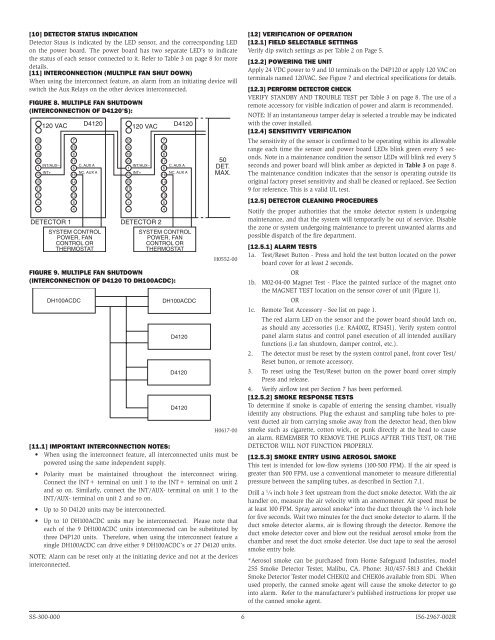
[11] interconnection (multiple fan shut down)<br />
When using the interconnect feature, an alarm from an initiating device will<br />
switch the Aux Relays on the other devices interconnected.<br />
Figure 8. Multiple Fan Shutdown<br />
(interconnection of D4120’s):<br />
10<br />
9<br />
19<br />
120 VAC D4120<br />
20<br />
INT/AUX–<br />
1<br />
INT+<br />
12<br />
15<br />
11<br />
2<br />
+<br />
–<br />
DETECTOR 1<br />
7<br />
18<br />
8<br />
17<br />
C, AUX A<br />
6<br />
NC, AUX A<br />
16<br />
14<br />
3<br />
13<br />
5<br />
4<br />
SYSTEM CONTROL<br />
POWER, FAN<br />
CONTROL OR<br />
THERMOSTAT<br />
10<br />
9<br />
19<br />
120 VAC D4120<br />
20<br />
INT/AUX–<br />
1<br />
INT+<br />
12<br />
15<br />
11<br />
2<br />
+<br />
–<br />
DETECTOR 2<br />
7<br />
18<br />
8<br />
17<br />
C, AUX A<br />
6<br />
NC, AUX A<br />
16<br />
14<br />
3<br />
13<br />
5<br />
4<br />
SYSTEM CONTROL<br />
POWER, FAN<br />
CONTROL OR<br />
THERMOSTAT<br />
Figure 9. Multiple Fan Shutdown<br />
(interconnection of D4120 to DH100ACDC):<br />
DH100ACDC<br />
DH100ACDC<br />
D4120<br />
D4120<br />
D4120<br />
50<br />
DET.<br />
MAX.<br />
H0552-00<br />
H0617-00<br />
[11.1] Important Interconnection Notes:<br />
• When using the interconnect feature, all interconnected units must be<br />
powered using the same independent supply.<br />
• Polarity must be maintained throughout the interconnect wiring.<br />
Connect the INT+ terminal on unit 1 to the INT+ terminal on unit 2<br />
and so on. Similarly, connect the INT/AUX- terminal on unit 1 to the<br />
INT/AUX- terminal on unit 2 and so on.<br />
• Up to 50 D4120 units may be interconnected.<br />
• Up to 10 DH100ACDC units may be interconnected. Please note that<br />
each of the 9 DH100ACDC units interconnected can be substituted by<br />
three D4P120 units. Therefore, when using the interconnect feature a<br />
single DH100ACDC can drive either 9 DH100ACDC’s or 27 D4120 units.<br />
NOTE: Alarm can be reset only at the initiating device and not at the devices<br />
interconnected.<br />
[12] verification of operation<br />
[12.1] field selectable settings<br />
Verify dip switch settings as per Table 2 on Page 5.<br />
[12.2] powering the unit<br />
Apply 24 VDC power to 9 and 10 terminals on the D4P120 or apply 120 VAC on<br />
terminals named 120VAC. See Figure 7 and electrical specifications for details.<br />
[12.3] perform detector check<br />
VERIFY STANDBY AND TROUBLE TEST per Table 3 on page 8. The use of a<br />
remote accessory for visible indication of power and alarm is recommended.<br />
NOTE: If an instantaneous tamper delay is selected a trouble may be indicated<br />
with the cover installed.<br />
[12.4] Sensitivity Verification<br />
The sensitivity of the sensor is confirmed to be operating within its allowable<br />
range each time the sensor and power board LEDs blink green every 5 seconds.<br />
Note in a maintenance condition the sensor LEDs will blink red every 5<br />
seconds and power board will blink amber as depicted in Table 3 on page 8.<br />
The maintenance condition indicates that the sensor is operating outside its<br />
original factory preset sensitivity and shall be cleaned or replaced. See Section<br />
9 for reference. This is a valid UL test.<br />
[12.5] Detector Cleaning Procedures<br />
Notify the proper authorities that the smoke detector system is undergoing<br />
maintenance, and that the system will temporarily be out of service. Disable<br />
the zone or system undergoing maintenance to prevent unwanted alarms and<br />
possible dispatch of the fire department.<br />
[12.5.1] Alarm Tests<br />
1a. Test/Reset Button - Press and hold the test button located on the power<br />
board cover for at least 2 seconds.<br />
OR<br />
1b. M02-04-00 Magnet Test - Place the painted surface of the magnet onto<br />
the MAGNET TEST location on the sensor cover of unit (Figure 1).<br />
OR<br />
1c. Remote Test Accessory - See list on page 1.<br />
The red alarm LED on the sensor and the power board should latch on,<br />
as should any accessories (i.e. RA400Z, RTS451). Verify system control<br />
panel alarm status and control panel execution of all intended auxiliary<br />
functions (i.e fan shutdown, damper control, etc.).<br />
2. The detector must be reset by the system control panel, front cover Test/<br />
Reset button, or remote accessory.<br />
3. To reset using the Test/Reset button on the power board cover simply<br />
Press and release.<br />
4. Verify airflow test per Section 7 has been performed.<br />
[12.5.2] Smoke Response Tests<br />
To determine if smoke is capable of entering the sensing chamber, visually<br />
identify any obstructions. Plug the exhaust and sampling tube holes to prevent<br />
ducted air from carrying smoke away from the detector head, then blow<br />
smoke such as cigarette, cotton wick, or punk directly at the head to cause<br />
an alarm. REMEMBER TO REMOVE THE PLUGS AFTER THIS TEST, OR THE<br />
DETECTOR WILL NOT FUNCTION PROPERLY.<br />
[12.5.3] Smoke Entry using Aerosol Smoke<br />
This test is intended for low-flow systems (100-500 FPM). If the air speed is<br />
greater than 500 FPM, use a conventional manometer to measure differential<br />
pressure between the sampling tubes, as described in Section 7.1.<br />
Drill a 1 ⁄4 inch hole 3 feet upstream from the duct smoke detector. With the air<br />
handler on, measure the air velocity with an anemometer. Air speed must be<br />
at least 100 FPM. Spray aerosol smoke* into the duct through the 1 ⁄4 inch hole<br />
for five seconds. Wait two minutes for the duct smoke detector to alarm. If the<br />
duct smoke detector alarms, air is flowing through the detector. Remove the<br />
duct smoke detector cover and blow out the residual aerosol smoke from the<br />
chamber and reset the duct smoke detector. Use duct tape to seal the aerosol<br />
smoke entry hole.<br />
*Aerosol smoke can be purchased from Home Safeguard Industries, model<br />
25S Smoke Detector Tester, Malibu, CA. Phone: 310/457-5813 and Chekkit<br />
Smoke Detector Tester model CHEK02 and CHEK06 available from SDi. When<br />
used properly, the canned smoke agent will cause the smoke detector to go<br />
into alarm. Refer to the manufacturer’s published instructions for proper use<br />
of the canned smoke agent.<br />
SS-300-000 6 <strong>I56</strong>-<strong>2967</strong>-<strong>002R</strong>