Create successful ePaper yourself
Turn your PDF publications into a flip-book with our unique Google optimized e-Paper software.
CAUTION<br />
Canned aerosol simulated smoke (canned smoke agent) formulas will vary by<br />
manufacturer. Misuse or overuse to these products may have long term adverse<br />
effects on the smoke detector. Consult the canned smoke agent manufacturer’s<br />
published instructions for any further warnings or caution statements.<br />
[12.6] Install The Cover<br />
Install the covers making sure that the cover fits into the base groove. Tighten<br />
the seven screws that are captured in the covers.<br />
NOTE: Verify sensor cover gasket is properly seated on cover prior to cover<br />
installation.<br />
[13] detector cleaning procedures<br />
Notify the proper authorities that the smoke detector system is undergoing<br />
maintenance, and that the system will temporarily be out of service. Disable<br />
the zone or system undergoing maintenance to prevent unwanted alarms and<br />
possible dispatch of the fire department.<br />
Figure 10. Detector sensor exploded view:<br />
SENSOR<br />
COVER<br />
COVER<br />
REMOVAL<br />
TABS<br />
SENSING<br />
CHAMBER<br />
COVER AND<br />
SCREEN<br />
SENSOR<br />
CHAMBER<br />
[13.1] Detector Sensor<br />
1. Remove the sensor to be cleaned from the system.<br />
H0584-00<br />
2. Remove the sensor cover by pulling outward on each of the four removal<br />
tabs that hold the cover in place. See Figure 10.<br />
3. Vacuum the screen carefully without removing it. If further cleaning is<br />
required continue with Step 4, otherwise skip to Step 7.<br />
4. Remove the chamber cover/screen assembly by pulling it straight out.<br />
5. Use a vacuum cleaner or compressed air to remove dust and debris from<br />
the sensing chamber.<br />
6. Reinstall the chamber cover/screen assembly by sliding the edge over the<br />
sensing chamber. Turn until it is firmly in place.<br />
7. Replace the cover using the holes for the LEDs for alignment and then<br />
gently pushing it until it locks into place.<br />
8. Reinstall the detector.<br />
[13.2] Reinstallation<br />
1. Reinstall the detector in its housing.<br />
2. Restore system power.<br />
3. Perform Detector Check, Section 12.3.<br />
4. Notify the proper authorities testing has been completed and the smoke<br />
detector system is back in operation.<br />
[14] Sensor Replacement (part no. 2D51)<br />
1. Remove the sensor head by rotating counterclockwise.<br />
2. Pull gently to remove it.<br />
3. To replace the sensor head, align the mounting features and rotate clockwise<br />
into place.<br />
[15] Optional accessories<br />
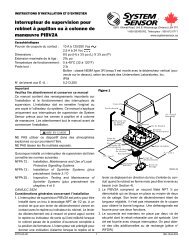
[15.1] RTS451/RTS451KEY Remote Test Station<br />
The RTS451/RTS451KEY Remote Test Station facilitates test of the alarm capability<br />
of the duct smoke detector as indicated in the RTS451/RTS451KEY manual.<br />
The D4120 duct smoke detector can be reset by the RTS451/RTS451KEY.<br />
To install the RTS451/RTS451KEY, connect the device as shown in Figure 12;<br />
wire runs must be limited to 25 ohms or less per interconnecting wire. If a<br />
system control panel is used, the panel itself may require testing.<br />
[15.2] SSK451 Multi-Signaling Accessory<br />
The SSK451 Multi-Signaling accessory combines a sounder feature with a key<br />
activated test and reset function. Green, amber and red LEDs provide a visual<br />
indication of power, trouble, and alarm respectively. An optional strobe<br />
(PS24LOW) with a smoke lens can be added to conform to the codes of certain<br />
jurisdictions.<br />
To install the SSK451, connect the device as shown in Figure 14.<br />
Figure 11. Wiring diagrams for optional accessories:<br />
SS-300-000 7 <strong>I56</strong>-<strong>2967</strong>-<strong>002R</strong><br />
ALARM<br />
AUX OUT –<br />
D4120<br />
DUCT DETECTOR<br />
15<br />
20<br />
(+)<br />
(–)<br />
MHR/MHW<br />
(OPTIONAL) AUDIO<br />
ALERT<br />
ALARM<br />
Figure 12. Wiring diagram for D4120<br />
to APA151 or APA451:<br />
APA151/451<br />
COMMON<br />
(RED LED) ALARM<br />
(GREEN LED) POWER<br />
1<br />
2<br />
3<br />
AUX OUT –<br />
D4120<br />
DUCT DETECTOR<br />
15<br />
20<br />
D4120<br />
10<br />
7<br />
9<br />
19<br />
20<br />
1<br />
AUX OUT +<br />
AUX OUT –<br />
18<br />
8<br />
17<br />
6<br />
12<br />
15 ALARM<br />
16<br />
14<br />
11 R TEST<br />
2 R RESET<br />
3<br />
+ ACC +<br />
13<br />
– ACC –<br />
5<br />
4<br />
(+)<br />
(–)<br />
RED<br />
RA400Z(OPTIONAL)<br />
REMOTE (LED)<br />
ANNUNCIATOR<br />
H0554-00<br />
FIELD<br />
INSTALLED<br />
JUMPER<br />
SUP, NO<br />
SUP, C<br />
NOTE: WIRING DIAGRAM SHOWN IS FOR D4120 4-WIRE DUCT SMOKE<br />
DETECTOR SYSTEM EQUIPPED WITHOUT A CONTROL PANEL.<br />
NOTE: A TROUBLE CONDITION IS INDICATED<br />
BY LOSS OF GREEN LED<br />
Figure 13. Wiring diagram for D4120 to RTS451/RTS451KEY:<br />
RTS451/RTS451KEY<br />
FIELD<br />
INSTALLED<br />
JUMPER<br />
(RED LED)<br />
ALARM<br />
(GREEN LED)<br />
POWER<br />
2<br />
4<br />
1<br />
5<br />
3<br />
6<br />
10<br />
D4120<br />
7<br />
9<br />
19<br />
AUX OUT + 18<br />
8<br />
20<br />
1<br />
AUX OUT –<br />
17<br />
6<br />
12<br />
15 ALARM<br />
16<br />
14<br />
11 R TEST<br />
2 R RESET<br />
3<br />
+ ACC +<br />
13<br />
– ACC –<br />
5<br />
4<br />
FOR RTS451KEY ONLY WITHOUT A CONTROL PANEL<br />
Figure 14. Wiring diagram for D4120 to SSK451:<br />
SSK451<br />
FIELD<br />
INSTALLED<br />
JUMPER<br />
FOR<br />
POWER +<br />
TEMPORAL<br />
POWER –<br />
PATTERN<br />
COMMON<br />
TEMPORAL SELECT<br />
ALARM SIGNAL<br />
TEST<br />
RESET<br />
SUP. SIGNAL<br />
5<br />
6<br />
3<br />
2<br />
1<br />
8<br />
7<br />
4<br />
10 D4120<br />
7<br />
9<br />
18<br />
19 AUX OUT +<br />
8<br />
20<br />
1<br />
AUX OUT – 17<br />
6<br />
12<br />
15 ALARM<br />
16<br />
14<br />
11 R TEST<br />
2 R RESET<br />
3<br />
+ ACC +<br />
13<br />
– ACC –<br />
5<br />
4<br />
SUP, NO<br />
SUP, C<br />
C1009-00<br />
H0582-00<br />
SUP, NO<br />
SUP, C<br />
NOTE: WIRING DIAGRAM SHOWN IS FOR D4120 4-WIRE DUCT SMOKE<br />
DETECTOR SYSTEM EQUIPPED WITHOUT A CONTROL PANEL.<br />
H0583-00