DS-9500NI-S NVR User's Manual - Lobeco
DS-9500NI-S NVR User's Manual - Lobeco
DS-9500NI-S NVR User's Manual - Lobeco

You also want an ePaper? Increase the reach of your titles
YUMPU automatically turns print PDFs into web optimized ePapers that Google loves.
<strong>DS</strong>-<strong>9500NI</strong>-S Series <strong>NVR</strong><br />
USER MANUAL<br />
Version 1.2.0
Hikvision® Network Digital Video Recorder User’s <strong>Manual</strong><br />
This manual, as well as the software described in it, is furnished under license and may be used or copied only in<br />
accordance with the terms of such license. The content of this manual is furnished for informational use only, is subject<br />
to change without notice, and should not be construed as a commitment by Hikvision Digital Technology Co., Ltd.<br />
(Hikvision). Hikvision assumes no responsibility or liability for any errors or inaccuracies that may appear in the book.<br />
Except as permitted by such license, no part of this publication may be reproduced, stored in a retrieval system, or<br />
transmitted, in any form or by any means, electronic, mechanical, recording, or otherwise, without the prior written<br />
permission of Hikvision.<br />
HIKVISION MAKES NO WARRANTIES, EXPRESS OR IMPLIED, INCLUDING WITHOUT LIMITATION THE<br />
IMPLIED WARRANTIES OF MERCHANTABILITY AND FITNESS FOR A PARTICULAR PURPOSE,<br />
REGARDING THE HIKVISION SOFTWARE. HIKVISION DOES NOT WARRANT, GUARANTEE, OR MAKE<br />
ANY REPRESENTATIONS REGARDING THE USE OR THE RESULTS OF THE USE OF THE HIKVISION<br />
SOFTWARE IN TERMS OF ITS CORRECTNESS, ACCURACY, RELIABILITY, CURRENTNESS, OR<br />
OTHERWISE. THE ENTIRE RISK AS TO THE RESULTS AND PERFORMANCE OF THE HIKVISION<br />
SOFTWARE IS ASSUMED BY YOU. THE EXCLUSION OF IMPLIED WARRANTIES IS NOT PERMITTED BY<br />
SOME STATES. THE ABOVE EXCLUSION MAY NOT APPLY TO YOU.<br />
IN NO EVENT WILL HIKVISION, ITS DIRECTORS, OFFICERS, EMPLOYEES, OR AGENTS BE LIABLE TO<br />
YOU FOR ANY CONSEQUENTIAL, INCIDENTAL, OR INDIRECT DAMAGES (INCLUDING DAMAGES FOR<br />
LOSS OF BUSINESS PROFITS, BUSINESS INTERRUPTION, LOSS OF BUSINESS INFORMATION, AND THE<br />
LIKE) ARISING OUT OF THE USE OR INABILITY TO USE THE HIKVISION SOFTWARE EVEN IF<br />
HIKVISION HAS BEEN ADVISED OF THE POSSIBILITY OF SUCH DAMAGES. BECAUSE SOME STATES DO<br />
NOT ALLOW THE EXCLUSION OR LIMITATION OF LIABILITY FOR CONSEQUENTIAL OR INCIDENTAL<br />
DAMAGES, THE ABOVE LIMITATIONS MAY NOT APPLY TO YOU.<br />
1
Preventive and Cautionary Tips<br />
Before connecting and operating your <strong>NVR</strong>, please be advised of the following tips:<br />
• Ensure unit is installed in a well-ventilated, dust-free environment.<br />
• Unit is designed for indoor use only.<br />
• Keep all liquids away from the <strong>NVR</strong>.<br />
• Ensure environmental conditions meet factory specifications.<br />
• Ensure unit is properly secured to a rack or shelf. Major shocks or jolts to the unit as a result of dropping it may cause<br />
damage to the sensitive electronics within the unit.<br />
• Use the <strong>NVR</strong> in conjunction with an UPS if possible.<br />
• Power down the unit before connecting and disconnecting accessories and peripherals.<br />
• A factory recommended HDD should be used for this device.<br />
2
TABLE OF CONTENTS<br />
C H A P T E R 1 ..................................................................................................................................... 5<br />
Introduction ........................................................................................................................................... 5<br />
1.1 Front Panel Introduction............................................................................................................ 6<br />
1.2 Starting and Shutting Down Your <strong>NVR</strong> .................................................................................... 8<br />
C H A P T E R 2 ................................................................................................................................... 10<br />
Network Parameters Configuration .................................................................................................. 10<br />
2.1 Hyper Terminal Setup ............................................................................................................. 11<br />
2.2 Network Configuration by Hyper Terminal ............................................................................ 13<br />
C H A P T E R 3 ................................................................................................................................... 15<br />
ActiveX Control Installation .............................................................................................................. 15<br />
C H A P T E R 4 ................................................................................................................................... 17<br />
User Login and Exit ............................................................................................................................ 17<br />
C H A P T E R 5 ................................................................................................................................... 19<br />
Preview ................................................................................................................................................. 19<br />
5.1 Preview ................................................................................................................................... 20<br />
5.1.1 Windows Division ........................................................................................................ 20<br />
5.1.2 Preview ......................................................................................................................... 21<br />
5.1.3 Preview Control ........................................................................................................... 21<br />
5.1.4 Stop Preview ................................................................................................................ 22<br />
5.2 Recording and Capturing Image ............................................................................................. 22<br />
5.2.1 Recording ..................................................................................................................... 22<br />
5.2.2 Capturing Image ........................................................................................................... 23<br />
5.3 Video Parameters Setting ........................................................................................................ 23<br />
C H A P T E R 6 ................................................................................................................................... 24<br />
PTZ Control......................................................................................................................................... 24<br />
C H A P T E R 7 ................................................................................................................................... 26<br />
Playback ............................................................................................................................................... 26<br />
7.1 Playback Query ....................................................................................................................... 27<br />
7.2 Play Recording File ................................................................................................................. 28<br />
7.3 Capturing Image and Download ............................................................................................. 29<br />
7.4 Remote Backup ....................................................................................................................... 30<br />
C H A P T E R 8 ................................................................................................................................... 31<br />
Log Search ........................................................................................................................................... 31<br />
C H A P T E R 9 ................................................................................................................................... 33<br />
Configuration ...................................................................................................................................... 33<br />
9.1 Local Configuration ................................................................................................................ 34<br />
9.2 IP Camera Configuration ........................................................................................................ 34<br />
9.2.1 Quick Add of IP camera ............................................................................................... 35<br />
9.2.2 Single Add of IP camera ............................................................................................... 36<br />
9.3 Recording Settings .................................................................................................................. 38<br />
9.3.1 Video Parameters ......................................................................................................... 39<br />
9.3.2 Schedule Recording ..................................................................................................... 39<br />
9.3.3 Motion Detection Recording ........................................................................................ 41<br />
9.3.4 Alarm Recording .......................................................................................................... 43<br />
9.3.5 Other Recording Modes ............................................................................................... 45<br />
9.4 Alarm Settings ......................................................................................................................... 45<br />
9.4.1 Motion Detection Alarm .............................................................................................. 45<br />
9.4.2 Signal Level Alarm ...................................................................................................... 46<br />
9.4.3 Video Loss .................................................................................................................... 47<br />
9.4.4 Video Tampering .......................................................................................................... 48<br />
3
9.4.5 Exceptions .................................................................................................................... 49<br />
9.5 Network Configuration ........................................................................................................... 50<br />
9.5.1 Basic Configuration ..................................................................................................... 50<br />
9.5.2 PPPoE Settings ............................................................................................................. 51<br />
9.5.3 DDNS Settings ............................................................................................................. 51<br />
9.5.4 NTP Settings ................................................................................................................ 51<br />
9.5.5 Net Disk Settings ......................................................................................................... 52<br />
9.5.6 E-Mail Settings ............................................................................................................ 52<br />
9.6 Channel Configuration ............................................................................................................ 53<br />
9.6.1 Channel Display Settings ............................................................................................. 53<br />
9.6.2 Video Mask .................................................................................................................. 53<br />
9.7 Account Management ............................................................................................................. 54<br />
9.8 Remote Upgrade ..................................................................................................................... 55<br />
9.9 HDD Settings .......................................................................................................................... 56<br />
C H A P T E R 10 ................................................................................................................................. 58<br />
Appendix .............................................................................................................................................. 58<br />
Glossary ........................................................................................................................................ 59<br />
FAQ ............................................................................................................................................... 60<br />
4
C H A P T E R 1<br />
Introduction<br />
5
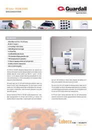
1.1 Front Panel Introduction<br />
<strong>DS</strong>-9504NI-S Front Panel:<br />
No. Name Description<br />
1 Status<br />
LED<br />
Indicators<br />
Power<br />
Alarm<br />
TX/RX<br />
HDD<br />
Ready<br />
Backup<br />
2 Power Button Powers <strong>NVR</strong> on/off.<br />
3<br />
4<br />
5<br />
USB Ports<br />
Channel Status<br />
Indicators<br />
Backup Button<br />
Turning red indicates power supply but without system running, turning blue<br />
indicates power supply and system running.<br />
Alarm indicator turns red when a sensor alarm is detected.<br />
TX/RX indictor blinks blue when network connection is functioning properly.<br />
HDD indicator blinks red when data is being read from or written to HDD.<br />
Ready indicator turns blue when <strong>NVR</strong> is functioning properly.<br />
Backup indicator blinks blue when data is being backup.<br />
Universal Serial Bus (USB) ports for additional devices such as USB mouse and<br />
USB Hard Disk Drive (HDD).<br />
Blue indicates recording, red indicates network connection, purple indicates<br />
recording & network connection.<br />
Backup video files. Press this button, <strong>NVR</strong> will backup all IP cameras’ 24-hour<br />
recorded video into USB flash memory.<br />
6
<strong>DS</strong>-9508NI-S Front Panel:<br />
No. Name Description<br />
1<br />
Status<br />
LED<br />
Indicators<br />
Power<br />
Alarm<br />
TX/RX<br />
HDD<br />
Ready<br />
Backup<br />
Turning red indicates power supply but without system running, turning blue<br />
indicates power supply and system running.<br />
Alarm indicator turns red when a sensor alarm is detected.<br />
TX/RX indictor blinks blue when network connection is functioning properly.<br />
HDD indicator blinks red when data is being read from or written to HDD.<br />
Ready indicator turns blue when <strong>NVR</strong> is functioning properly.<br />
Backup indicator blinks blue when data is being backup.<br />
USB Ports Universal Serial Bus (USB) ports for additional devices such as USB mouse and<br />
2<br />
USB Hard Disk Drive (HDD).<br />
3 Power Button Powers <strong>NVR</strong> on/off.<br />
4<br />
5<br />
Backup Button<br />
Channel Status Indicators<br />
Backup video files. Press this button, <strong>NVR</strong> will backup all IP cameras’ 24-hour<br />
recorded video into USB flash memory.<br />
Blue indicates recording, red indicates network connection, purple indicates<br />
recording & network connection.<br />
7
<strong>DS</strong>-9516NI-S Front Panel:<br />
No.<br />
1<br />
Name<br />
Status<br />
LED<br />
Indicators<br />
Power<br />
Alarm<br />
TX/RX<br />
HDD<br />
Ready<br />
Description<br />
Turning red indicates power supply but without system running, turning blue<br />
indicates power supply and system running.<br />
Alarm indicator turns red when a sensor alarm is detected.<br />
TX/RX indictor blinks blue when network connection is functioning properly.<br />
HDD indicator blinks red when data is being read from or written to HDD.<br />
Ready indicator turns blue when <strong>NVR</strong> is functioning properly.<br />
Backup<br />
Backup indicator blinks blue when data is being backup.<br />
2<br />
Backup Button Backup video files. Press this button, <strong>NVR</strong> will backup all IP cameras’ 24-hour<br />
recorded video into USB flash memory.<br />
3<br />
USB Ports Universal Serial Bus (USB) ports for additional devices such as USB mouse and<br />
USB Hard Disk Drive (HDD).<br />
4 Power Button Powers <strong>NVR</strong> on/off.<br />
5<br />
Channel Status<br />
Indicators<br />
Blue indicates recording, red indicates network connection, purple indicates<br />
recording & network connection.<br />
1.2 Starting and Shutting Down Your <strong>NVR</strong><br />
Power On<br />
If the power LED indicator on the front panel is off, please plug the power supply into an electrical outlet, the LED<br />
should turn red, indicating the unit is receiving power.<br />
When the LED is red, please press the Power button on the front panel. The Power indicator will turn blue. The unit<br />
will begin to start.<br />
Note: <strong>DS</strong>-<strong>9500NI</strong>-S series <strong>NVR</strong> do not have local output, when Ready indicator turns blue, that means the unit is<br />
power on and ready to be configured.<br />
8
Power Off<br />
Standard Shutdown<br />
Press and hold the POWER button for 3 seconds; the device will enter power off process, when power indicator turns<br />
red, turn off the power switch on the back panel.<br />
Other Methods of Shutdown<br />
Shutdown with Power Switch<br />
Please try to avoid shutting down the unit by turn off the power switch on the back panel (especially during recording).<br />
Shutdown by Unplug Power Supply<br />
Please try to avoid shutting down the unit by unplug power supply (especially during recording).<br />
Note: It is highly recommended that an Uninterruptible Power Supply (UPS) be used in conjunction with the unit.<br />
9
C H A P T E R 2<br />
Network Parameters Configuration<br />
10
<strong>DS</strong>-<strong>9500NI</strong>-S Series <strong>NVR</strong> are mainly for IPC, DVS network video storage and playback. Network configurations are<br />
needed before operating, including: IP address, subnet mask, gateway and port.<br />
Note: The factory default username is admin, password is 12345.<br />
The factory default IP address of <strong>DS</strong>-<strong>9500NI</strong>-S series is 192.168.0.1.<br />
2.1 Hyper Terminal Setup<br />
The common method is to connect <strong>NVR</strong> and PC with serial line, run Hyper Terminal and modify parameters with serial<br />
command. Please connect the RS-232 port of <strong>NVR</strong> with the COM port of PC directly, power on the <strong>NVR</strong> and PC and<br />
follow the steps:<br />
Step 1: Enter Hyper Terminal.<br />
Click “Start”-> “Programs” -> “Accessories” -> “Communications” -> “Hyper Terminal” in Windows system, and the<br />
dialogue box below will appears as Figure 2.1.1.<br />
Figure 2.1.1<br />
Step 2: Name the connection and define the icon.<br />
Input a name (e.g. HK), select an icon, and press “OK” to enter “Connect To” dialogue box.<br />
Step 3: Select the communication port.<br />
Select “COM1” in “Connect To” inter face (Please select the COM port according to the reality, in case PC has more<br />
than 1 COM.) Press “OK” to enter “Properties” dialogue box.<br />
11
Figure 2.1.2<br />
Step 4: Serial port setup.<br />
Set port parameters in “COM1 Properties” dialogue box as follow: (Fig 2.1.3)<br />
Figure 2.1.3<br />
The parameters should be:<br />
Bits per second: 115200<br />
Data bits: 8<br />
Parity: None<br />
Stop bits: 1<br />
Flow control: None<br />
Press “Apply” and “OK” after the setup. Press “Enter” under Hyper Terminal interface. When “[root@dvrdvs/]#”<br />
appears, the connection is established.<br />
12
Figure 2.1.4<br />
Step5: Disconnect and save connection.<br />
According to the tips, disconnect and save “HK” for the next time. After saving, there will be a new “Hyper Terminal”<br />
item established in the program group “Start”-> “Accessories”->“Communications”->“Hyper Terminal”. “Connection”<br />
names of all Hyper Terminal are included. You can see an icon named as “HK” here.<br />
2.2 Network Configuration by Hyper Terminal<br />
Enter Hyper Terminal<br />
Click “Start”->“Programs”->“Accessories”->“Communications”->“Hyper Terminal”->“HK”, then the Hyper Terminal<br />
interface will appear as figure below. Type “Enter”, and the prompt “[root@dvrdvs/]#” will appear which means<br />
connection between RS232 interface of PC and RS232 interface of <strong>NVR</strong> is established successfully by Hyper Terminal.<br />
The following operation commands are to accomplish the parameters setup in the prompt.<br />
13
Figure 2.2.1<br />
Commands<br />
Utilities<br />
helpm Console help command is used to print common commands, show as Figure 2.2.1.<br />
getIp Show the current IP address of <strong>NVR</strong>. Command format: getIp “Enter”.<br />
setIp<br />
Setup <strong>NVR</strong> IP address. Command format: setIp IP: mask<br />
e.g. setIp 192..168.1.11:255.255.255.0<br />
getPort Show the current port of <strong>NVR</strong>. Command format: getPort “Enter”.<br />
setPort<br />
Setup <strong>NVR</strong> port. Command format: setPort Port<br />
e.g. setPort 9000<br />
getGateway Show current <strong>NVR</strong> gateway address. Command format: getGateway “Enter”.<br />
setGateway<br />
Setup <strong>NVR</strong> gateway. Command format: setGateway Gateway<br />
e.g. setGateway 192.168.1.1<br />
14
C H A P T E R 3<br />
ActiveX Control Installation<br />
15
<strong>DS</strong>-<strong>9500NI</strong>-S series <strong>NVR</strong> can be accessed and configured by web server. Open IE browser, input the IP address of<br />
<strong>DS</strong>-<strong>9500NI</strong>-S and then click Enter. The system will remind you to install the ActiveX control. After the installation,<br />
you can configure and manage the <strong>NVR</strong> remotely.<br />
The ActiveX control has English and Chinese to selections. It can be used under 1024*768, 1152*864, 1280*1024<br />
display resolutions.<br />
Note: Please use IE 6.0 or IE 7.0 as browser, and upgrade OS to the latest version.<br />
16
C H A P T E R 4<br />
User Login and Exit<br />
17
Open IE browser, input the IP address of <strong>NVR</strong>, the web server will select the language automatically according to the<br />
system language and maximize the IE browser.<br />
Figure 4.1<br />
On the top right corner, language is selectable between Chinese and English.<br />
Input the correct user name, password and port, click “Login” to enter preview interface, or it will pop up an error box.<br />
The default user name is admin, password is 12345, and port is 8000.<br />
After login, click “Exit” to log off and return to the login interface.<br />
18
C H A P T E R 5<br />
Preview<br />
19
After login, the preview interface will display:<br />
Figure 5.1<br />
Interface description:<br />
Area Description Area Description<br />
Channel list<br />
Live view<br />
PTZ<br />
Video adjustment<br />
Play control<br />
Play control buttons description:<br />
Button Description Button Description<br />
1 window division 4 windows division<br />
9 windows division 16 windows division<br />
Stop all preview<br />
Capture image<br />
Start all recording<br />
Stop all recording<br />
Previous page<br />
Next page<br />
Open/ Close audio<br />
5.1 Preview<br />
5.1.1 Windows Division<br />
When live preview, the windows division can be selected by click the button on play control area. It can support 1, 4, 9<br />
and 16 windows division. The change between different windows division modes will not stop the current preview; the<br />
window still can be operated.<br />
20
5.1.2 Preview<br />
Preview by channel:<br />
After choosing window division mode, select one<br />
window, and click on channel list to preview the<br />
current channel. If preview successful, the icon will<br />
become .<br />
Preview by page:<br />
Click the device node on the list, then multiple<br />
channels will start to display synchronously<br />
according to the selected window divisions. Click<br />
5.1.3 to switch Preview to the next page, Control click to the previous<br />
page.<br />
Or just click and to start preview by page.<br />
Double click to maximize:<br />
Click the selected window can maximize the window<br />
to full screen, double click again to resume.<br />
Full screen display:<br />
Click to change the multi-channel preview to<br />
full screen, click to resume.<br />
When previewing, select the channel, and click<br />
to open audio, the status will be . Then click to<br />
open audio scroll bar and adjust the audio. After the<br />
adjustment, the bar will disappear automatically.<br />
When audio is open, click<br />
status will resume to .<br />
to close audio and the<br />
Note: When preview with web server, only one channel audio can be previewed at one time.<br />
21
5.1.4 Stop Preview<br />
Click on the playlist, it will become . This<br />
can stop the channel preview.<br />
Click<br />
to stop all channels preview.<br />
5.2 Recording and Capturing Image<br />
The previewing channel is required when recording and capturing image.<br />
Note: When stop previewing, will also stop the recording of this channel.<br />
5.2.1 Recording<br />
Click “Config”, enter local configuration menu<br />
where can change the directory of saving recording<br />
file and the size of file packing.<br />
Click button on playlist to start recording of this<br />
channel, if the icon is not , it will note “Recording<br />
failed”.<br />
Click icon again to stop recording, and the saving<br />
file folder will pop up automatically.<br />
When multiple channels are under previewing, user may<br />
click to start all channel recording, or click to<br />
stop all channel recording.<br />
Stop previewing will also stop recording of this<br />
channel.<br />
22
Note: If saving file disk space is less than 500M, the web server will stop recording automatically.<br />
5.2.2 Capturing Image<br />
Click “Config” to enter local configuration menu, where can<br />
modify the saving capturing image directory.<br />
Select a previewing window, click to capture image. If<br />
capture image successfully, the saving folder will pop up<br />
automatically.<br />
Note: When disk space is less than 500M, capture image will be failed.<br />
5.3 Video Parameters Setting<br />
Select the previewing channel, and adjust the brightness,<br />
contrast, saturation and Hue for it.<br />
Click to increase and click to decrease. Click or<br />
can also adjust the value.<br />
Click icon to resume the default values.<br />
23
C H A P T E R 6<br />
PTZ Control<br />
24
If the front-end connects with PTZ, PTZ control is available when preview.<br />
With the direction buttons, it can achieve 8 directions control.<br />
Also zoom, focus, iris, light and wiper are adjustable.<br />
Click to enable auto scan, click again to stop it.<br />
If preset point is set, the point can be called by selecting in the<br />
draw down list and clicking .<br />
25
C H A P T E R 7<br />
Playback<br />
26
Click “Playback” to enter playback menu.<br />
Figure 7.1<br />
Playback interface description:<br />
Area Description Area Description<br />
Channel list<br />
Playback video<br />
Playback control<br />
Playback status<br />
Calendar<br />
Download/ Backup<br />
Timeline<br />
Playback control buttons description:<br />
Button Description Button Description<br />
Play<br />
Stop<br />
Slow down<br />
Speed up<br />
Play by single frame<br />
Snapshot<br />
Video clip<br />
Open/Close audio<br />
7.1 Playback Query<br />
Step 1:<br />
Select a channel on the channel list. (Channel 1 is the default.)<br />
27
Step 2:<br />
Select a date in calendar.<br />
Step 3:<br />
Click “Search” to search the matched recorded files. If there are search results, then they will be shown in the time line<br />
area.<br />
Drag the timeline to select the specific time. Different file types will be indicated with different colors.<br />
7.2 Play Recording File<br />
After searching file, click<br />
to play.<br />
When playback, the playback status will indicate<br />
the channel number, time and status.<br />
28
Recording file location:<br />
Click , input the time in the pop-up box and click “Go”.<br />
This will start the file playback from the specified time.<br />
Drag timeline, and set “ ” to the specified time to play back<br />
the video.<br />
7.3 Capturing Image and Download<br />
Click “Config” to enter local configuration menu, where<br />
can change saving directory of captured image and<br />
recorded file.<br />
When playback, click to capture image. If capturing image successfully, the saving image folder will pop up<br />
automatically.<br />
When playback, click to pop up saving file window. After<br />
the selection, the status will become , click again to stop<br />
saving.<br />
29
After searching file, click to pop up a new<br />
page where list all the files for the specific day.<br />
Select one file and click to start download, click<br />
again to stop download.<br />
During download, the window will display the file number<br />
and download progress.<br />
7.4 Remote Backup<br />
<strong>DS</strong>-<strong>9500NI</strong>-S series <strong>NVR</strong> support local one key backup function, and it can also support backup to USB storage<br />
devices remotely.<br />
After searching files, click to pop up a new page<br />
where list all the files for the specific day.<br />
Select the backup device, enable backup player or not, select<br />
the files and click to start backup, click again to<br />
stop backup.<br />
During backup, the window will display the file number and<br />
backup progress.<br />
Note: If USB device cannot be detected, please try to connect again. If it still cannot be detected, this may be because<br />
of the compatible problem between <strong>NVR</strong> and backup device.<br />
30
C H A P T E R 8<br />
Log Search<br />
31
Click “Log” to enter log query menu:<br />
Figure 8.1<br />
Select the log type and date, and click to list all<br />
matched logs.<br />
Enable “Start” as<br />
of a day.<br />
to search the log file in a certain period<br />
Click can export the logs as Excel or TXT file.<br />
Note: Up to 2000 logs can be listed; if the items are more than 2000, please choose a certain period and search again.<br />
32
C H A P T E R 9<br />
Configuration<br />
33
Click “Config” button in the menu bar and enter parameters setup menu, which displays local configuration by default.<br />
9.1 Local Configuration<br />
Figure 9.1<br />
Local Parameters Information:<br />
Local<br />
Configurations<br />
Parameters<br />
Protocol Type<br />
The Size of File Packaging<br />
Stream Type<br />
Network Transmission<br />
Feature<br />
Path for saving recording<br />
files<br />
Path for saving preview<br />
captured images<br />
Path for saving playback<br />
captured images<br />
Path for saving download<br />
files<br />
Descriptions<br />
Select network transmission protocol: TCP or UDP.<br />
Set the size of recordings<br />
Main Stream for recording. Substream for viewing<br />
live images.<br />
Set real-time and fluency of network feature<br />
Select a folder to save the recordings<br />
Select a folder to save the pictures captured while<br />
preview<br />
Select a folder to save the pictures captured while<br />
playback<br />
Select a folder to save downloaded recordings<br />
9.2 IP Camera Configuration<br />
Click “Remote Config” and enter IP camera configuration menu.<br />
34
Figure 9.2<br />
Model Name<br />
<strong>DS</strong>-9504NI-S<br />
<strong>DS</strong>-9508NI-S<br />
<strong>DS</strong>-9516NI-S<br />
IP camera connections<br />
Up to 4-ch D1 or 2-ch 720P or 1-ch UXGA IP cameras<br />
Up to 8-ch D1 or 4-ch 720P or 2-ch UXGA IP cameras<br />
Up to 16-ch D1 or 8-ch 720P or 4-ch UXGA IP cameras<br />
Note: For <strong>DS</strong>-2CD852MF series IP camera at UXGA resolution, up to 1 channel can be connected to <strong>DS</strong>-9504NI-S<br />
model, 2 channels to <strong>DS</strong>-9508NI-S model and 4 channels to <strong>DS</strong>-9516NI-S model.<br />
9.2.1 Quick Add of IP camera<br />
<strong>DS</strong>-<strong>9500NI</strong>-S series <strong>NVR</strong> provides a function of remote auto searching IP camera. When there are supported IP<br />
cameras in the same network segment of a LAN with <strong>NVR</strong>, you may add it in one button with default user name,<br />
password and port number.<br />
Note: Before applying Quick Add function, please make sure that IP camera is compatible with <strong>NVR</strong> and default user<br />
name, password, port number are not changed.<br />
Click<br />
, the on-line IP cameras will be listed as figure below shown:<br />
35
Figure 9.3<br />
Tick a box in front of the listed camera and click OK to finish.<br />
9.2.2 Single Add of IP camera<br />
This function enables you to add a single IP camera quickly. When there are supported IP cameras in the same network<br />
segment of a LAN with <strong>NVR</strong>, you may add it in one button with default user name, password and port number.<br />
Note: Before applying Single Add function, please make sure that IP camera is compatible with <strong>NVR</strong> and default<br />
user name, password, port number are not changed.<br />
First, select a Channel No. then click<br />
and the on-line IP cameras will be listed as figure below shown:<br />
36
Figure 9.4<br />
Select one camera in the list and click to finish.<br />
Then you can change IP address, sub mask or user name, password in the menu on the right, and click “Modify” to<br />
confirm.<br />
<strong>Manual</strong>ly Add IP camera<br />
First select a Channel No. to enable IP camera Config menu shown on the right.<br />
Input the IP address, port, user name and password, click “Modify” to finish adding an IP<br />
camera that will be listed in the IP Camera Information area.<br />
Clicking Reset button will restore the configurations of IPC back to the previous ones.<br />
Clicking button will delete the selected IP camera.<br />
37
9.3 Recording Settings<br />
Click “Remote Config” and select<br />
recording, alarm, network settings and etc.<br />
to enter remote settings menu where you can configure<br />
Figure 9.5<br />
38
9.3.1 Video Parameters<br />
Figure 9.6<br />
Settings for recording:<br />
Items<br />
Encoding<br />
Parameters<br />
Stream Type<br />
Resolution<br />
Bit rate Type<br />
Frame Type<br />
Descriptions<br />
Main Stream (Normal/Event) and Sub stream.<br />
Video and Video & Audio<br />
Recording Resolution<br />
Variable and Constant<br />
BBP,BP and Single P<br />
9.3.2 Schedule Recording<br />
Step1: Enable Schedule Recording.<br />
Note: When <strong>NVR</strong> is succeed to connect to IP camera, it will start schedule recording which means recording<br />
for 7/24.<br />
39
Figure 9.7<br />
Step 2: Set recording time and type.<br />
Click Settings button besides to “Record Time” to enter setup<br />
page.<br />
Select one day in a week, and select All Day recording if<br />
necessary. You may also set period recording by disable All<br />
Day Recording; there are 8 time periods in one day. Then you<br />
can select schedule recording from the drop-down menu<br />
beside the periods. Then you may also select copy the settings<br />
to whole week or to one day.<br />
Note: Please make sure that each time period is not<br />
overlapped.<br />
40
In the “Advanced Record Settings”, you may configure<br />
parameters of Pre Record time, Post Record time, Recordings<br />
Duration, Redundant Recording and whether to record audio.<br />
9.3.3 Motion Detection Recording<br />
Go to Motion Detection page:<br />
Figure 9.8<br />
Note: If you are using IP camera that is not from Hikvision, please setup this function by using its own software.<br />
Step1: Select Channel No. for motion detection recording.<br />
Step2: Enable motion detection by tick the box.<br />
Step3: Then you can click settings buttons to set area, arm schedule and linkage.<br />
41
Step4: Tick box of Start Draw and draw an area on the image<br />
by lift-pressing and holding the mouse. Double-click can<br />
select full screen.<br />
Step5: Select a sensitivity level for motion detection. Level 1<br />
is the lowest, 6 is the highest.<br />
Step6: Arm Schedule Setup<br />
You may select one day in a week, or select several time<br />
periods in one day. Then you may also select copy the settings<br />
to whole week or to one day.<br />
Note: There are 8 time periods in one day.<br />
Step7: Go back to Schedule Record page and click settings<br />
button besides Record Time to enter Recording Schedule<br />
menu.<br />
Step8: Select one day in a week, and select All Day recording<br />
if necessary. You may also set period recording by disable All<br />
Day Recording; there are 8 time periods in one day. Then you<br />
can select Motion Detection from the drop-down menu beside<br />
the periods. Then you may also select copy the settings to<br />
whole week or to one day.<br />
Note:<br />
(1) Please make sure that each time period is not overlapped.<br />
(2)The valid time of motion detection recording is the<br />
intersection of arm schedule and recoding schedule.<br />
42
9.3.4 Alarm Recording<br />
Select<br />
<br />
Step1: Select alarm input.<br />
Note: It refers to the alarm input of IP channel.<br />
Step2: Select the type of alarm input, “NO” or “NC”.<br />
Note: “NO” is the default status. The settings will become<br />
effective after rebooting.<br />
If you are using IP camera that is not from Hikvision, please<br />
setup this function by using its own software.<br />
Step3: Enable “Alarm Handle” to activate “Arm Schedule” &<br />
“Linkage Method”.<br />
43
Step4: Set the fortify time for alarm input.<br />
Click “Settings” in “Fortify Time” menu. Select “Weekday”<br />
as some day of the week or the whole week for recording<br />
time. The “All Day Record” or 8 “Segments” can be selected<br />
as well.<br />
Note: The time of each segment can not be overlapped.<br />
Step5: Set recording channel triggered by alarm.<br />
Click “Settings” in “Linkage” menu and select “Trigger<br />
Recording” tab.<br />
Enable the recording channels you want.<br />
Step6: Enter schedule recording interface. Click<br />
to enable Recording.<br />
44
Step7: Select one day in a week, and select All Day recording<br />
if necessary. You may also set period recording by disable All<br />
Day Recording; there are 8 time periods in one day. Then you<br />
can select Alarm Recording from the drop-down menu beside<br />
the periods. Then you may also select copy the settings to<br />
whole week or to one day.<br />
Note:<br />
(1) Please make sure that each time period is not overlapped.<br />
(2)The valid time of alarm recording is the intersection of arm<br />
schedule and recoding schedule.<br />
9.3.5 Other Recording Modes<br />
Other Recording Modes are including “Motion detection & Alarm”, “Motion detection | Alarm”.<br />
“&” means recording is triggered when two situations happened together.<br />
“|” means recording is triggered when one of the situations happened.<br />
The configurations are the same with “Motion detection recording” or “Alarm recording”.<br />
9.4 Alarm Settings<br />
You can configure motion detection alarm, signal level alarm, video loss alarm and other alarm and linkage through<br />
web client.<br />
9.4.1 Motion Detection Alarm<br />
Step1: The same with the Step 1 of Section 9.3.3 Motion Detection Recording.<br />
Step2: The same with the Step 2 of Section 9.3.3 Motion Detection Recording.<br />
Step3: The same with the Step 3 of Section 9.3.3 Motion Detection Recording.<br />
Step4: The same with the Step 4 of Section 9.3.3 Motion Detection Recording.<br />
45
Step5: Set the alarm linkage for motion detection and select<br />
alarm output channel.<br />
Alarm Linkages Description:<br />
Linkage<br />
Warning on Monitor<br />
Audio Warning<br />
Upload to Center<br />
E-mail Linkage<br />
Trigger Alarm Output<br />
Description<br />
When the alarm signal is detected, the image of corresponding channel will pop out as<br />
single screen.<br />
Alarm triggers buzzer<br />
Upload the alarm signal to the center, such as client software<br />
When the alarm signal is detected, the client software will send the email to the<br />
designated mailbox.<br />
Trigger alarm output of the device; if the device is 9000 series, triggering alarm output<br />
of IP channel can be selected as well.<br />
9.4.2 Signal Level Alarm<br />
Step1: The same with the Step1 of Section 9.3.4 Alarm Recording.<br />
Step2: The same with the Step2 of Section 9.3.4 Alarm Recording.<br />
Step3: The same with the Step3 of Section 9.3.4 Alarm Recording.<br />
Step4: The same with the Step4 of Section 9.3.4 Alarm Recording.<br />
Step5: Set the alarm linkage for signal level and select alarm<br />
output channel.<br />
46
Step6: Set PTZ linkage for signal level alarm.<br />
Note: Alarm input can link PTZ of several channels, but<br />
one channel can only link one option of preset, sequence and<br />
pattern.<br />
9.4.3 Video Loss<br />
Note: This function is only available on IP cameras from Hikvision.<br />
Step1: Select the channel number for video loss.<br />
Select<br />
<br />
Step2: Enable “Video Loss” to activate settings of “Fortify<br />
Time” and “Linkage”<br />
Step3: Set the fortify time for video loss.<br />
Click “Settings” in “Fortify Time” menu.<br />
Select “Weekday” as some day of the week or the whole week<br />
for the fortify time.<br />
The “All Day Record” or 8 “Segments” can be selected as<br />
well.<br />
Note: The time of each segment can not be overlapped.<br />
47
Step4: Set linkage for video loss.<br />
Click “Settings” in the “Linkage” menu.<br />
9.4.4 Video Tampering<br />
Note: This function is only available on IP cameras from Hikvision.<br />
Step1: Select the channel number for video tampering.<br />
Select<br />
<br />
Step2: Enable “Video Tampering Alarm” to activate settings<br />
of “Area Settings”, “Arm Schedule” and “Linkage”.<br />
48
区 域 、 布 防 时 间 和 联 动 方 式 的 设 置 。<br />
Step3: Set the video tampering area and sensitivity.<br />
The sensitivity can be divided into three levels: Low,<br />
Medium, and High.<br />
Enable “Start Draw”, and select the detection area by using<br />
mouse.<br />
Step4: Set the fortify time for video tampering.<br />
Click “Settings” in “Arm Schedule” menu.<br />
Select “Weekday” as some day of the week or the whole week<br />
for the arm schedule.<br />
The “All Day Record” or 8 “Periods” can be selected as well.<br />
Note: The time of each segment can not be overlapped.<br />
Step5: Set linkage for video tampering.<br />
Click “Settings” in the “Linkage” menu.<br />
9.4.5 Exceptions<br />
Exception parameters are for the alarm handle of abnormal event, which is including “HDD Full”, “HDD Fault” (HDD<br />
errors or HDD not initialization), “Network Broken”, “IP Address Conflict”, “Illegal Access” (user name or password<br />
wrong), “Video Output Standard Mismatch” and “Video Signal Exception” (video signal unstable).<br />
49
Select the exception type and handle method.<br />
Select<br />
to enter configuration<br />
interface.<br />
9.5 Network Configuration<br />
9.5.1 Basic Configuration<br />
Select<br />
<br />
Configure the network according to the actual situation. If<br />
there is DHCP server in the network, enable “Obtain Auto”<br />
and reboot the device to get the IP address under this network<br />
segment automatically.<br />
Select “Advance” to enter advanced configuration. You can<br />
configure preferred DNS server1 and spare DNS server2, IP<br />
address of alarm host and IP server.<br />
Parameters<br />
DNS1 DNS2<br />
Alarm host<br />
IP sever<br />
Description<br />
Preferred and spare DNS server<br />
Alarm signal can be uploaded to the IP address automatically<br />
IP address of IP server<br />
50
9.5.2 PPPoE Settings<br />
Select<br />
<br />
Enable PPPoE by ticking , input the user name and<br />
password, then save the changes and reboot the device to<br />
make the parameters become effective.<br />
If succeed to dial, the current IP address will be displayed in<br />
the blank “DDNS IP”.<br />
9.5.3 DDNS Settings<br />
Adopting DDNS function can solve the problems caused by dynamic IP.<br />
Click<br />
<br />
Enable DDNS.<br />
If the “IP Server IP” is selected as protocol, then input the<br />
address where the IP server is running.<br />
If the “Dyndns” is selected as protocol:<br />
Server Name: Input the IP address of the server, such as<br />
members.dyndns.org;<br />
Domain: the domain name that user applied for the device,<br />
such as test.dynlia.com;<br />
User name, password and verify: the account information that<br />
user registered on the Dyndns website.<br />
If the “Peanut Hull” is selected as protocol:<br />
Input the user name and password applied on the Peanut Hull<br />
website to visit the device by the applied domain name.<br />
9.5.4 NTP Settings<br />
Adopting NTP function can enable client software to synchronize the time and data of the device regularly.<br />
51
Select<br />
<br />
Tick to enable NTP function.<br />
Note: Time Synchronization Interval: 0~10080 min (default<br />
60min).<br />
If the device connected to the public network, the IP address<br />
of NTP server provided by carrier can be input in the blank<br />
“Server Address”;<br />
If the device connected to private network, the IP address of<br />
NTP server built by NTP software can be input the blank<br />
“Server Address”.<br />
9.5.5 Net Disk Settings<br />
By Net Disk Settings, recorded data can be saved to the network storage disk provided by NAS or IP SAN server.<br />
Select<br />
<br />
Input the IP address of NAS or IP SAN server in the blank<br />
“Server IP address”; input the saving path allocated by NAS<br />
or IP SAN server in the blank “File Path”.<br />
Note:<br />
1. Make sure that the device supports NFS function and<br />
NAS or IP SAN server allocated the storage space<br />
correctly.<br />
2. Up to 1 IP SAN server is allowable to be used.<br />
9.5.6 E‐Mail Settings<br />
Through E-mail configuration, the e-mail can be sent to the designated mailbox when there is an alarm.<br />
Select<br />
<br />
If server authentication is needed, enable it (i.e. ) and input<br />
user name and password.<br />
Input the sender and recipient information, if it needs to send<br />
picture, you can enable “Attachment” (i.e. ).<br />
Note: Currently the function of captured picture attachment<br />
is invalid for <strong>DS</strong>-9500 NI-S.<br />
52
9.6 Channel Configuration<br />
9.6.1 Channel Display Settings<br />
Note: This function is only available on IP cameras from Hikvision.<br />
Select<br />
<br />
You can configure channel name, OSD and related<br />
parameters here.<br />
9.6.2 Video Mask<br />
Note: This function is only available on IP cameras from Hikvision.<br />
Step1: Select channel number, and enable video mask<br />
(i.e. ).<br />
Select<br />
<br />
53
Step2: Set the mask area.<br />
Click “Settings” to enter area set menu.<br />
Enable “Start Draw” (i.e. ), select the mask area by clicking<br />
and dragging the mouse.<br />
Note: Max. 4 areas can be configured in one image.<br />
9.7 Account Management<br />
The default user name and password of device administrator are “admin” and “12345”. Administrator can remote add,<br />
delete users or distribute authority for users. The new added users are divided into two levels: user and operator. (For<br />
“Remote Configuration” privilege, operator has “Voice Talk” right, user does not; for “Channel Configuration”<br />
privilege, operator has all the rights, user has local playback, remote playback rights.)<br />
Select<br />
54
Click “Add” to add user.<br />
Note: If you set the IP address or physical address, and then<br />
only the PC with the same IP address or physical address can<br />
visit the device through network.<br />
Note:<br />
Local PTZ Control: Locally control PTZ cameras.<br />
Local <strong>Manual</strong> Record: Locally start and stop manual recording on any of the channels.<br />
Local Playback: Locally play recorded files that are on the <strong>NVR</strong>.<br />
Local Parameters Settings: Configure the settings, restore to default settings, import/export configuration file.<br />
Local Log Query: Search and view logs of <strong>NVR</strong>.<br />
Local Advanced Operation: HDD management (including the initialization and changing the properties of a<br />
disk). Ability to update system firmware as well as to stop the relay output.<br />
Local Camera Management: Enable and disable analog channels. Ability to add and delete IP cameras.<br />
Local Backup: Locally backup recorded files from any of the channels.<br />
Local Shutdown/Reboot: Shutdown or reboot the <strong>NVR</strong>.<br />
Remote PTZ Control: Remotely control PTZ cameras.<br />
Remote <strong>Manual</strong> Record: Remotely start and stop manual recording on any of the channels.<br />
Remote Playback: Remotely play and download recorded files that are on the <strong>NVR</strong>.<br />
Remote Configuration: Remotely configure parameters, restore parameters to factory defaults and import<br />
settings to as well as export settings from <strong>NVR</strong>.<br />
Remote Log Search: Remotely view logs that are saved on the <strong>NVR</strong>.<br />
Remote Advanced Operation: Remotely manage hard disk drives (initializing and setting properties for HDDs).<br />
Ability to remote update system firmware and stop of the relay output.<br />
Voice Talking: Ability to use two-way radio between the remote client and the <strong>NVR</strong>.<br />
Remote preview: Select and view live video over the network.<br />
Remote Alarm Control: Remote alert or control the relay output of the <strong>NVR</strong>. Alarm and exception settings must<br />
be configured properly to upload to host.<br />
Remote Video Output Control: Send remote button control signal.<br />
Remote Serial Port Control: Configure settings for RS232 and RS485 ports.<br />
Remote Camera Management: Remotely enable and disable analog channels. Add and delete IP cameras.<br />
Remote Shutdown/Reboot: Remotely shutdown or reboot the <strong>NVR</strong>.<br />
9.8 Remote Upgrade<br />
Remote Upgrade:<br />
Click<br />
Click “Browse” to search the local upgrade file, click<br />
“Upgrade” to start upgrade remotely.<br />
55
9.9 HDD Settings<br />
HDD Formatting:<br />
Click<br />
Note: Please backup the data before formatting hard disk.<br />
Disk Group Management:<br />
Select one disk and select one HDD Group you want it to be<br />
shown as figure right.<br />
Note: <strong>NVR</strong> supports up to 16 HDD Groups.<br />
HDD Property Settings:<br />
Select one disk, and configure its property by selecting<br />
Read-Write, Read-Only or redundant from drop-down menu,<br />
shown as figure right.<br />
Note:<br />
Read-Write: Writing in or Read from this disk is allowed<br />
when selecting this option.<br />
Write-Only: Unable to write in this disk to protect existed<br />
recordings from being overwritten when selecting this option.<br />
Redundant: Redundant recording in this disk is allowed<br />
when selecting this option.<br />
56
HDD Group record channel:<br />
Click “HDD Group attribute” button to enter setup page.<br />
First select a HDD group and then tick channels you want to<br />
record in this HDD group, and then click OK to finish<br />
Note: Recording the images of one channel in one HDD<br />
group is recommended.<br />
57
C H A P T E R 10<br />
Appendix<br />
58
Glossary<br />
DHCP<br />
Dynamic Host Configuration Protocol (DHCP) is a network application protocol used by devices (DHCP clients) to<br />
obtain configuration information for operation in an Internet Protocol network.<br />
NTP<br />
Acronym for Network Time Protocol. A protocol designed to synchronize the clocks of computers over a network.<br />
PPPoE<br />
PPPoE, Point-to-Point Protocol over Ethernet, is a network protocol for encapsulating Point-to-Point Protocol (PPP)<br />
frames inside Ethernet frames. It is used mainly with A<strong>DS</strong>L services where individual users connect to the A<strong>DS</strong>L<br />
transceiver (modem) over Ethernet and in plain Metro Ethernet networks.<br />
DDNS<br />
Dynamic DNS is a method, protocol, or network service that provides the capability for a networked device, such as a<br />
router or computer system using the Internet Protocol Suite, to notify a domain name server to change, in real time<br />
(ad-hoc) the active DNS configuration of its configured hostnames, addresses or other information stored in DNS.<br />
MTU<br />
Maximum Transmission Unit. Unit is represented by bytes. MTU of most network devices is 1500. If it’s bigger than<br />
gateway MTU, the data packets will be split into smaller ones for transmission. In this case, there will be pieces of data<br />
packet causing packet loss ratio to raise and slow down network speed. When MTU is preset smaller than the gateway<br />
MTU, the packet loss ratio will decrease.<br />
<strong>NVR</strong><br />
Acronym for Network Video Recorder. An <strong>NVR</strong> can be a PC-based or embedded system used for centralized<br />
management and storage for IP cameras, IP Domes and other DVRs.<br />
59
FAQ<br />
• Why does my <strong>NVR</strong> make a beeping sound after booting?<br />
There are a few reasons for the warning beep your <strong>NVR</strong> makes after booting.<br />
1. There is no HDD present in the <strong>NVR</strong>.<br />
2. The HDD has not been initialized.<br />
3. The HDD is defective.<br />
If you wish to use your <strong>NVR</strong> without any HDDs, you may disable this warning beep in the Exception Settings menu<br />
(See Exceptions).<br />
• Why is there no video recorded after setting the motion detection?<br />
If there are no recorded video after setting the motion detection, please check:<br />
1. Check that the recording schedule is setup correctly by following the steps listed in Schedule Recording.<br />
2. Check that the motion detection area is configured correctly (See Motion Detection).<br />
3. Make sure that channels are being triggered for motion detection (See Motion Detection).<br />
• Why doesn’t the <strong>NVR</strong> detect my USB export device for exporting recorded files?<br />
There’s a chance that the <strong>NVR</strong> and your USB device is not compatible. Please refer to our company’s website to view a<br />
list of compatible devices.<br />
60