Hesterberg GmbH - Chapter pipe drop hangers

Create successful ePaper yourself
Turn your PDF publications into a flip-book with our unique Google optimized e-Paper software.
HESTERBERG<br />
Rohrabhängungen<br />
Pipe <strong>drop</strong> <strong>hangers</strong><br />
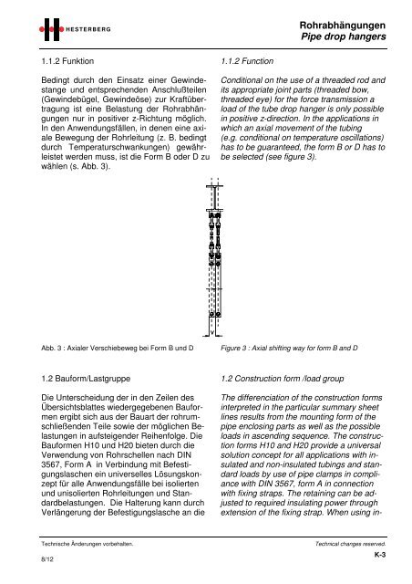
1.1.2 Funktion<br />
Bedingt durch den Einsatz einer Gewindestange<br />
und entsprechenden Anschlußteilen<br />
(Gewindebügel, Gewindeöse) zur Kraftübertragung<br />
ist eine Belastung der Rohrabhängungen<br />
nur in positiver z-Richtung möglich.<br />
In den Anwendungsfällen, in denen eine axiale<br />
Bewegung der Rohrleitung (z. B. bedingt<br />
durch Temperaturschwankungen) gewährleistet<br />
werden muss, ist die Form B oder D zu<br />
wählen (s. Abb. 3).<br />
1.1.2 Function<br />
Conditional on the use of a threaded rod and<br />
its appropriate joint parts (threaded bow,<br />
threaded eye) for the force transmission a<br />
load of the tube <strong>drop</strong> hanger is only possible<br />
in positive z-direction. In the applications in<br />
which an axial movement of the tubing<br />
(e.g. conditional on temperature oscillations)<br />
has to be guaranteed, the form B or D has to<br />
be selected (see figure 3).<br />
Abb. 3 : Axialer Verschiebeweg bei Form B und D<br />
Figure 3 : Axial shifting way for form B and D<br />
1.2 Bauform/Lastgruppe<br />
Die Unterscheidung der in den Zeilen des<br />
Übersichtsblattes wiedergegebenen Bauformen<br />
ergibt sich aus der Bauart der rohrumschließenden<br />
Teile sowie der möglichen Belastungen<br />
in aufsteigender Reihenfolge. Die<br />
Bauformen H10 und H20 bieten durch die<br />
Verwendung von Rohrschellen nach DIN<br />
3567, Form A in Verbindung mit Befestigungslaschen<br />
ein universelles Lösungskonzept<br />
für alle Anwendungsfälle bei isolierten<br />
und unisolierten Rohrleitungen und Standardbelastungen.<br />
Die Halterung kann durch<br />
Verlängerung der Befestigungslasche an die<br />
1.2 Construction form /load group<br />
The differenciation of the construction forms<br />
interpreted in the particular summary sheet<br />
lines results from the mounting form of the<br />
<strong>pipe</strong> enclosing parts as well as the possible<br />
loads in ascending sequence. The construction<br />
forms H10 and H20 provide a universal<br />
solution concept for all applications with insulated<br />
and non-insulated tubings and standard<br />
loads by use of <strong>pipe</strong> clamps in compliance<br />
with DIN 3567, form A in connection<br />
with fixing straps. The retaining can be adjusted<br />
to required insulating power through<br />
extension of the fixing strap. When using in-<br />
Technische Änderungen vorbehalten.<br />
8/12<br />
Technical changes reserved.<br />
K-3