Unreinforced masonry diaphragm walls - Concrete Block Association
Unreinforced masonry diaphragm walls - Concrete Block Association
Unreinforced masonry diaphragm walls - Concrete Block Association

Create successful ePaper yourself
Turn your PDF publications into a flip-book with our unique Google optimized e-Paper software.
Design applications<br />
Equation 1<br />
Equation 2<br />
Equation 3<br />
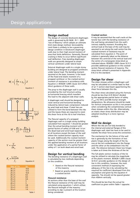
Size of Tie Kv<br />
35 x 5 14.6<br />
30 x 5 12.5<br />
25 x 5 10.4<br />
20 x 5 8.3<br />
25 x 4 8.3<br />
20 x 4 6.6<br />
15 x 4 5<br />
20 x 3 5<br />
15 x 3 3.8<br />
10 x 3 2.5<br />
10 x 2 1.6<br />
Equation 4<br />
Table 1<br />
Design method<br />
The design of concrete blockwork <strong>diaphragm</strong><br />
<strong>walls</strong> is governed by BS 5628 : Pt 1 : 2005<br />
‘Use of Masonry’ which adopts an ultimate<br />
limit state design method. Serviceability<br />
Limit State is unlikely to be a governing<br />
design condition in blockwork <strong>diaphragm</strong><br />
<strong>walls</strong> due to their high second moment of<br />
area that limits deflection. Generally, flexural<br />
cracking is likely to occur before significant<br />
wall deflection. Free standing <strong>diaphragm</strong><br />
<strong>walls</strong> are generally designed as simple<br />
vertical cantilevers under lateral load.<br />
External <strong>diaphragm</strong> <strong>walls</strong> to a single storey<br />
building are designed as propped cantilevers<br />
under lateral load. The bending moment<br />
assumed at the base, however, is the lesser<br />
of the fixed end elastic moment of a<br />
propped cantilever or the cracked section<br />
moment of resistance in accordance with<br />
Equation 2. BS5628-1:2005 clause 32.9 offers<br />
direct guidance of these <strong>walls</strong>.<br />
The prop to the <strong>diaphragm</strong> wall is usually<br />
provided by the roof structure acting<br />
as horizontal bracing which transfers<br />
the load to the adjacent side shear <strong>walls</strong>.<br />
A <strong>diaphragm</strong> wall should be designed to<br />
resist vertical and horizontal bending<br />
induced by lateral load, compression induced<br />
by axial load and shear. If steel ties are<br />
utilised to form the bond between the ribs<br />
and the leaves these are required to resist<br />
the shear force at the rib to leaf interface.<br />
The flexural capacity of a propped<br />
<strong>diaphragm</strong> wall in a single storey building<br />
calculated from equation 1 should be greater<br />
than the actual bending moment with<br />
partial factors of safety of 0.90 and 1.4 on<br />
the dead load and wind load respectively<br />
at all locations except the base of the wall<br />
where the cracked section capacity must<br />
be used. Additionally the cracked moment<br />
capacity of the section must be greater than<br />
the applied bending moment at all locations<br />
under the application of a partial factor of<br />
safety of 1 on both dead and wind load.<br />
Design for vertical bending<br />
The bending resistance of a <strong>diaphragm</strong> wall<br />
is calculated by two methods depending<br />
on the condition.<br />
• Based on the flexural resistance<br />
of the <strong>masonry</strong><br />
• Based on gravity stability utilising<br />
a cracked section<br />
Flexural resistance<br />
At sections other than the base of the wall<br />
the flexural resistance of the wall may be<br />
calculated using equations 1 which utilises<br />
the flexural strength of the <strong>masonry</strong><br />
providing no dpc is present at the location<br />
being considered.<br />
Cracked section<br />
It may be assumed that the wall cracks at the<br />
tensile face with the bending resistance of<br />
the wall being calculated from the wall’s<br />
intrinsic stability moment. Providing the<br />
vertical load at the base of the wall may be<br />
assumed to act along the wall centre line the<br />
cracked moment of resistance may be<br />
calculated from equation 2. The point of<br />
rotation is generally taken as the distance<br />
between the centroid of the vertical load and<br />
the centre of a rectangular stress block as<br />
indicated above. BS5628-1:2005 clause 32.5.3<br />
provides additional guidance on the cracked<br />
section flexural resistance of <strong>masonry</strong>. The<br />
stress block utilised is presented in Appendix<br />
B B.2 to the standard.<br />
Design for shear<br />
The shear stresses within a <strong>diaphragm</strong> wall<br />
may be calculated on a similar basis to that<br />
of an ‘I’ section steel beam apportioning the<br />
shear force between the ribs.<br />
The shear stress calculated using this formula<br />
should be less than 0.35 N/mm 2 divided<br />
by the appropriate partial factor of safety<br />
(ϒ mv ) for M12 and M6 mortar strength<br />
designations. No allowance should be made<br />
for vertical compression as this is not present<br />
when considering the complimentary vertical<br />
shear stresses within the ribs. Alternatively,<br />
an elastic shear stress distribution may be<br />
adopted resulting in a more rigorous<br />
analysis.<br />
Wall tie design<br />
Where the ribs are not fully bonded to<br />
the internal and external flanges of the<br />
<strong>diaphragm</strong> wall, steel ties have to be used to<br />
transfer the shear force across the connection.<br />
The mechanism for the failure of the wall<br />
ties is generally by the formation of two<br />
plastic hinges along the length of the tie,<br />
one at the tie’s embedment into the flange<br />
and the other at the embedment into the<br />
web. The distance between these two hinges<br />
is taken as 6 times the thickness of the tie.<br />
The full plastic section modulus of the tie<br />
may be utilised to calculate the magnitude<br />
of the plastic moment. BS5628-1:2005 clause<br />
32.9.4.1 provides guidance on the design of<br />
ties in this condition, however, the most<br />
convenient method of expressing the<br />
adequacy of the ties is by calculating the<br />
required tie coefficient developed from this<br />
assumption and given by the equation 4<br />
opposite. Ties should not be spaced greater<br />
than 450mm vertically.<br />
This should be less than the actual tie<br />
coefficient as given within Table 1 opposite.