Unreinforced masonry diaphragm walls - Concrete Block Association
Unreinforced masonry diaphragm walls - Concrete Block Association
Unreinforced masonry diaphragm walls - Concrete Block Association

Create successful ePaper yourself
Turn your PDF publications into a flip-book with our unique Google optimized e-Paper software.
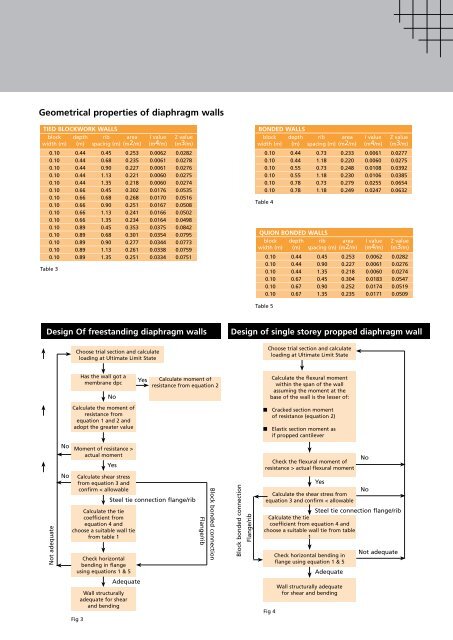
Geometrical properties of <strong>diaphragm</strong> <strong>walls</strong><br />
TIED BLOCKWORK WALLS<br />
block depth rib area I value Z value<br />
width (m) (m) spacing (m) (m2/m) (m4/m) (m3/m)<br />
0.10 0.44 0.45 0.253 0.0062 0.0282<br />
0.10 0.44 0.68 0.235 0.0061 0.0278<br />
0.10 0.44 0.90 0.227 0.0061 0.0276<br />
0.10 0.44 1.13 0.221 0.0060 0.0275<br />
0.10 0.44 1.35 0.218 0.0060 0.0274<br />
0.10 0.66 0.45 0.302 0.0176 0.0535<br />
0.10 0.66 0.68 0.268 0.0170 0.0516<br />
0.10 0.66 0.90 0.251 0.0167 0.0508<br />
0.10 0.66 1.13 0.241 0.0166 0.0502<br />
0.10 0.66 1.35 0.234 0.0164 0.0498<br />
0.10 0.89 0.45 0.353 0.0375 0.0842<br />
0.10 0.89 0.68 0.301 0.0354 0.0795<br />
0.10 0.89 0.90 0.277 0.0344 0.0773<br />
0.10 0.89 1.13 0.261 0.0338 0.0759<br />
0.10 0.89 1.35 0.251 0.0334 0.0751<br />
Table 3<br />
BONDED WALLS<br />
block depth rib area I value Z value<br />
width (m) (m) spacing (m) (m2/m) (m4/m) (m3/m)<br />
0.10 0.44 0.73 0.233 0.0061 0.0277<br />
0.10 0.44 1.18 0.220 0.0060 0.0275<br />
0.10 0.55 0.73 0.248 0.0108 0.0392<br />
0.10 0.55 1.18 0.230 0.0106 0.0385<br />
0.10 0.78 0.73 0.279 0.0255 0.0654<br />
0.10 0.78 1.18 0.249 0.0247 0.0632<br />
Table 4<br />
QUION BONDED WALLS<br />
block depth rib area I value Z value<br />
width (m) (m) spacing (m) (m2/m) (m4/m) (m3/m)<br />
0.10 0.44 0.45 0.253 0.0062 0.0282<br />
0.10 0.44 0.90 0.227 0.0061 0.0276<br />
0.10 0.44 1.35 0.218 0.0060 0.0274<br />
0.10 0.67 0.45 0.304 0.0183 0.0547<br />
0.10 0.67 0.90 0.252 0.0174 0.0519<br />
0.10 0.67 1.35 0.235 0.0171 0.0509<br />
Table 5<br />
Design Of freestanding <strong>diaphragm</strong> <strong>walls</strong><br />
Design of single storey propped <strong>diaphragm</strong> wall<br />
Choose trial section and calculate<br />
loading at Ultimate Limit State<br />
Choose trial section and calculate<br />
loading at Ultimate Limit State<br />
Has the wall got a<br />
membrane dpc<br />
No<br />
Yes<br />
Calculate moment of<br />
resistance from equation 2<br />
Calculate the flexural moment<br />
within the span of the wall<br />
assuming the moment at the<br />
base of the wall is the lesser of:<br />
Calculate the moment of<br />
resistance from<br />
equation 1 and 2 and<br />
adopt the greater value<br />
■ Cracked section moment<br />
of resistance (equation 2)<br />
■ Elastic section moment as<br />
if propped cantilever<br />
Not adequate<br />
No<br />
No<br />
Moment of resistance ><br />
actual moment<br />
Yes<br />
Calculate shear stress<br />
from equation 3 and<br />
confirm < allowable<br />
Calculate the tie<br />
coefficient from<br />
equation 4 and<br />
choose a suitable wall tie<br />
from table 1<br />
Check horizontal<br />
bending in flange<br />
using equations 1 & 5<br />
Steel tie connection flange/rib<br />
Flange/rib<br />
<strong>Block</strong> bonded connection<br />
<strong>Block</strong> bonded connection<br />
Flange/rib<br />
Check the flexural moment of<br />
resistance > actual flexural moment<br />
Yes<br />
Calculate the shear stress from<br />
equation 3 and confirm < allowable<br />
Check horizontal bending in<br />
flange using equation 1 & 5<br />
No<br />
No<br />
Steel tie connection flange/rib<br />
Calculate the tie<br />
coefficient from equation 4 and<br />
choose a suitable wall tie from table<br />
1<br />
Adequate<br />
Not adequate<br />
Adequate<br />
Wall structurally<br />
adequate for shear<br />
and bending<br />
Fig 4<br />
Wall structurally adequate<br />
for shear and bending<br />
Fig 3