Unreinforced masonry diaphragm walls - Concrete Block Association
Unreinforced masonry diaphragm walls - Concrete Block Association
Unreinforced masonry diaphragm walls - Concrete Block Association

You also want an ePaper? Increase the reach of your titles
YUMPU automatically turns print PDFs into web optimized ePapers that Google loves.
Cl/SfB Ff2<br />
May 2010<br />
Data Sheet 10<br />
Aggregate concrete blocks<br />
<strong>Unreinforced</strong> <strong>masonry</strong> <strong>diaphragm</strong> <strong>walls</strong><br />
Depth<br />
Depth<br />
Depth<br />
Depth<br />
Depth<br />
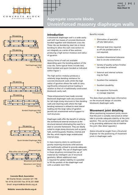
Rib spacing<br />
Rib spacing<br />
Rib spacing<br />
Rib spacing<br />
First course<br />
Second course<br />
Tied Diaphragm Wall<br />
Fig 1A<br />
First course<br />
Second course<br />
Bonded Diaphragm Wall<br />
Fig 1B<br />
Rib spacing<br />
Introduction<br />
A blockwork <strong>diaphragm</strong> wall is a wide cavity<br />
wall with two leaves of concrete blockwork<br />
bonded together with blockwork cross ribs.<br />
These ribs are bonded by steel ties or block<br />
bonding to allow the wall cross section to<br />
act integrally as a series of box sections<br />
producing a high section modulus and radius<br />
of gyration.<br />
Various forms of wall are available<br />
depending upon the bonding pattern of the<br />
cross ribs. Some typical forms include tied,<br />
block bonded and quoin bonded as indicated<br />
within Figure 1.<br />
The high section modulus produces a<br />
relatively large bending resistance for<br />
concrete blockwork <strong>walls</strong> whilst the high<br />
radius of gyration allows the <strong>walls</strong> to carry<br />
significantly enhanced vertical loading in<br />
relation to that of a traditionally constructed<br />
blockwork cavity wall.<br />
These enhancements have made concrete<br />
blockwork <strong>diaphragm</strong> <strong>walls</strong> very economical<br />
for tall single storey structures or free standing<br />
<strong>walls</strong> and retaining <strong>walls</strong> where the high<br />
bending resistance is utilised to resist lateral<br />
loading and the large radius of gyration<br />
permits tall unrestrained vertical support to<br />
roof structures.<br />
Diaphragm <strong>walls</strong> offer the benefit of utilising<br />
the architectural external enclosure as the<br />
structural element eliminating the need for a<br />
steel or concrete framework. They are ideally<br />
suited to single storey structures such as sports<br />
halls, swimming pools, theatres, cinemas and<br />
the like, which require large unobstructed<br />
internal areas.<br />
Benefits include:<br />
• Elimination of specialist<br />
off-site fabrication.<br />
• Minimal lead time required<br />
as off-site prefabrication is<br />
not required.<br />
• Excellent dimensional tolerance<br />
due to on-site construction.<br />
• Variety of quality surface finishes<br />
can easily be achieved.<br />
• External and internal surfaces<br />
may be flush.<br />
• Excellent fire resistance.<br />
• Excellent durability.<br />
• No expensive formwork<br />
or cranage required.<br />
This data sheet provides basic information<br />
on the structural design of concrete<br />
blockwork <strong>diaphragm</strong> <strong>walls</strong>.<br />
Movement joint detailing<br />
When positioning movement joints, ensure<br />
that the joint is suitably restrained at either<br />
side to provide adequate stability at the joint<br />
position. This can be achieved with wall ties<br />
or by providing additional ribs to stabilise<br />
the joint. (See detail opposite.)<br />
Advice should be sought from a Structural<br />
Engineer for the positioning of movement<br />
joints in <strong>diaphragm</strong> <strong>walls</strong>.<br />
Depth<br />
Quoin Bonded Diaphragm Wall<br />
Fig 1C<br />
(Ribs either side of joint)<br />
Movement joint<br />
Movement joint detail<br />
Movement Joint Detail<br />
Fig 1D<br />
In mass <strong>masonry</strong> stems to cantilevered<br />
gravity retaining structures solid sections<br />
are traditionally utilised to provide adequate<br />
flexural strength. The use of <strong>diaphragm</strong> <strong>walls</strong><br />
in these situations minimised the use of<br />
materials by intelligent use of structural<br />
geometry. Where additional mass<br />
is required for global stability it is possible<br />
to fill the pockets of the <strong>diaphragm</strong> wall<br />
with a suitable inert filler.<br />
<strong>Concrete</strong> <strong>Block</strong> <strong>Association</strong><br />
60 Charles Street, Leicester LE1 1FB<br />
Tel: 0116 253 6161 Fax: 0116 251 4568<br />
Email: enquiries@cba-blocks.org.uk<br />
Website: www.cba-blocks.org.uk
Design applications<br />
Equation 1<br />
Equation 2<br />
Equation 3<br />
Size of Tie Kv<br />
35 x 5 14.6<br />
30 x 5 12.5<br />
25 x 5 10.4<br />
20 x 5 8.3<br />
25 x 4 8.3<br />
20 x 4 6.6<br />
15 x 4 5<br />
20 x 3 5<br />
15 x 3 3.8<br />
10 x 3 2.5<br />
10 x 2 1.6<br />
Equation 4<br />
Table 1<br />
Design method<br />
The design of concrete blockwork <strong>diaphragm</strong><br />
<strong>walls</strong> is governed by BS 5628 : Pt 1 : 2005<br />
‘Use of Masonry’ which adopts an ultimate<br />
limit state design method. Serviceability<br />
Limit State is unlikely to be a governing<br />
design condition in blockwork <strong>diaphragm</strong><br />
<strong>walls</strong> due to their high second moment of<br />
area that limits deflection. Generally, flexural<br />
cracking is likely to occur before significant<br />
wall deflection. Free standing <strong>diaphragm</strong><br />
<strong>walls</strong> are generally designed as simple<br />
vertical cantilevers under lateral load.<br />
External <strong>diaphragm</strong> <strong>walls</strong> to a single storey<br />
building are designed as propped cantilevers<br />
under lateral load. The bending moment<br />
assumed at the base, however, is the lesser<br />
of the fixed end elastic moment of a<br />
propped cantilever or the cracked section<br />
moment of resistance in accordance with<br />
Equation 2. BS5628-1:2005 clause 32.9 offers<br />
direct guidance of these <strong>walls</strong>.<br />
The prop to the <strong>diaphragm</strong> wall is usually<br />
provided by the roof structure acting<br />
as horizontal bracing which transfers<br />
the load to the adjacent side shear <strong>walls</strong>.<br />
A <strong>diaphragm</strong> wall should be designed to<br />
resist vertical and horizontal bending<br />
induced by lateral load, compression induced<br />
by axial load and shear. If steel ties are<br />
utilised to form the bond between the ribs<br />
and the leaves these are required to resist<br />
the shear force at the rib to leaf interface.<br />
The flexural capacity of a propped<br />
<strong>diaphragm</strong> wall in a single storey building<br />
calculated from equation 1 should be greater<br />
than the actual bending moment with<br />
partial factors of safety of 0.90 and 1.4 on<br />
the dead load and wind load respectively<br />
at all locations except the base of the wall<br />
where the cracked section capacity must<br />
be used. Additionally the cracked moment<br />
capacity of the section must be greater than<br />
the applied bending moment at all locations<br />
under the application of a partial factor of<br />
safety of 1 on both dead and wind load.<br />
Design for vertical bending<br />
The bending resistance of a <strong>diaphragm</strong> wall<br />
is calculated by two methods depending<br />
on the condition.<br />
• Based on the flexural resistance<br />
of the <strong>masonry</strong><br />
• Based on gravity stability utilising<br />
a cracked section<br />
Flexural resistance<br />
At sections other than the base of the wall<br />
the flexural resistance of the wall may be<br />
calculated using equations 1 which utilises<br />
the flexural strength of the <strong>masonry</strong><br />
providing no dpc is present at the location<br />
being considered.<br />
Cracked section<br />
It may be assumed that the wall cracks at the<br />
tensile face with the bending resistance of<br />
the wall being calculated from the wall’s<br />
intrinsic stability moment. Providing the<br />
vertical load at the base of the wall may be<br />
assumed to act along the wall centre line the<br />
cracked moment of resistance may be<br />
calculated from equation 2. The point of<br />
rotation is generally taken as the distance<br />
between the centroid of the vertical load and<br />
the centre of a rectangular stress block as<br />
indicated above. BS5628-1:2005 clause 32.5.3<br />
provides additional guidance on the cracked<br />
section flexural resistance of <strong>masonry</strong>. The<br />
stress block utilised is presented in Appendix<br />
B B.2 to the standard.<br />
Design for shear<br />
The shear stresses within a <strong>diaphragm</strong> wall<br />
may be calculated on a similar basis to that<br />
of an ‘I’ section steel beam apportioning the<br />
shear force between the ribs.<br />
The shear stress calculated using this formula<br />
should be less than 0.35 N/mm 2 divided<br />
by the appropriate partial factor of safety<br />
(ϒ mv ) for M12 and M6 mortar strength<br />
designations. No allowance should be made<br />
for vertical compression as this is not present<br />
when considering the complimentary vertical<br />
shear stresses within the ribs. Alternatively,<br />
an elastic shear stress distribution may be<br />
adopted resulting in a more rigorous<br />
analysis.<br />
Wall tie design<br />
Where the ribs are not fully bonded to<br />
the internal and external flanges of the<br />
<strong>diaphragm</strong> wall, steel ties have to be used to<br />
transfer the shear force across the connection.<br />
The mechanism for the failure of the wall<br />
ties is generally by the formation of two<br />
plastic hinges along the length of the tie,<br />
one at the tie’s embedment into the flange<br />
and the other at the embedment into the<br />
web. The distance between these two hinges<br />
is taken as 6 times the thickness of the tie.<br />
The full plastic section modulus of the tie<br />
may be utilised to calculate the magnitude<br />
of the plastic moment. BS5628-1:2005 clause<br />
32.9.4.1 provides guidance on the design of<br />
ties in this condition, however, the most<br />
convenient method of expressing the<br />
adequacy of the ties is by calculating the<br />
required tie coefficient developed from this<br />
assumption and given by the equation 4<br />
opposite. Ties should not be spaced greater<br />
than 450mm vertically.<br />
This should be less than the actual tie<br />
coefficient as given within Table 1 opposite.
Equation 5<br />
ECCENTRICITY AT TOP OF<br />
SR DIAPHRAGM WALL, ex<br />
h/D up to<br />
0.05D 0.1D 0.2D 0.3D 0.4D 0.5D<br />
0 1.00 0.90 0.74 0.60 0.38 0<br />
6 1.00 0.90 0.74 0.60 0.38 0<br />
8 1.00 0.90 0.74 0.60 0.38 0<br />
10 0.98 0.90 0.74 0.60 0.38 0<br />
12 0.95 0.89 0.74 0.60 0.38 0<br />
14 0.91 0.85 0.74 0.60 0.38 0<br />
16 0.86 0.81 0.72 0.60 0.38 0<br />
18 0.80 0.75 0.68 0.60 0.38 0<br />
20 0.75 0.72 0.63 0.55 0.38 0<br />
22 0.71 0.67 0.59 0.49 0.28 0<br />
24 0.66 0.62 0.53 0.36 0.13 0<br />
26 0.60 0.56 0.43 0.21 0 0<br />
27 0.57 0.52 0.34 0.11 0 0<br />
28 0.53 0.47 0.26 0.03 0 0<br />
30 0.42 0.30 0.07 0 0 0<br />
Table 2 Capacity Reduction Factor, β<br />
Equation 6<br />
Design for<br />
horizontal bending<br />
The flanges of the <strong>diaphragm</strong> wall have to<br />
span horizontally between the internal ribs<br />
under the action of the lateral pressure.<br />
Since the flange is continuous over the<br />
ribs the applied bending moment may be<br />
taken as:<br />
This should be less than the flexural moment<br />
of resistance of the wall (failure<br />
perpendicular to the bed joints) as given in<br />
clause 32.4.3 in BS 5628 : Pt 1 : 2005 and<br />
given here as equation 1. Within equation 1<br />
g d should be taken as zero in this condition.<br />
To allow full utilisation of the flange in using<br />
the box section analysis of the <strong>diaphragm</strong><br />
wall the centres of the ribs should generally<br />
not exceed 12 times the thickness of the<br />
flange plus the thickness of the web in<br />
accordance with the clause 32.4.3 of BS 5628<br />
: Pt 1 : 2005.<br />
Design for vertical load<br />
The vertical load resistance of a <strong>diaphragm</strong><br />
wall is calculated in accordance with clause<br />
28.2.2 of BS 5628 : Pt 1 : 2005 as represented<br />
by equation 6 adjacent.<br />
The capacity reduction factor may be taken<br />
from table 2 taking effective thickness of the<br />
<strong>diaphragm</strong> as the actual thickness.<br />
Alternatively, the designer may wish to use<br />
table 7 of BS 5628 : Pt 1 : 2005 with the<br />
effective thickness being based on the<br />
equivalent thickness of a section with the<br />
same radius of gyration as the <strong>diaphragm</strong><br />
wall under consideration.<br />
The vertical load resistance of a <strong>diaphragm</strong><br />
wall is seldom critical in the standard design<br />
case of a single storey building.<br />
Movement<br />
Movement within the wall may occur due<br />
to temperature or moisture variation or<br />
horizontal movement within the roof<br />
structure. Provision for such movement<br />
should be via vertical movement joints at<br />
centres indicated in BS 5628 : Pt 3 or consult<br />
the block manufacturer.<br />
Construction<br />
Diaphragm <strong>walls</strong> to buildings gain their<br />
stability from the restraint provided by<br />
the roof structure at their head. During<br />
construction such restraint is not available;<br />
provision should therefore be made to<br />
provide temporary lateral restraint during<br />
construction.<br />
Means of providing stability to the<br />
<strong>diaphragm</strong> wall should be noted to the<br />
contractor so that any requirements for<br />
temporary bracing may be considered.<br />
Insulation<br />
Diaphragm <strong>walls</strong> have large cavities, which<br />
can incorporate insulation as required.<br />
Alternatively, <strong>walls</strong> can be insulated either<br />
internally or externally.<br />
The U value for the overall wall construction<br />
should be calculated using the proportional<br />
area method given in BS EN ISO 6946.<br />
Detail consideration<br />
Durability<br />
Environmental conditions will need to<br />
be considered when selecting mortar and<br />
block type.<br />
Detailed provisions on durability are not<br />
given here.<br />
Reference should be made to BS 5628 : Pt 3.
Geometrical properties of <strong>diaphragm</strong> <strong>walls</strong><br />
TIED BLOCKWORK WALLS<br />
block depth rib area I value Z value<br />
width (m) (m) spacing (m) (m2/m) (m4/m) (m3/m)<br />
0.10 0.44 0.45 0.253 0.0062 0.0282<br />
0.10 0.44 0.68 0.235 0.0061 0.0278<br />
0.10 0.44 0.90 0.227 0.0061 0.0276<br />
0.10 0.44 1.13 0.221 0.0060 0.0275<br />
0.10 0.44 1.35 0.218 0.0060 0.0274<br />
0.10 0.66 0.45 0.302 0.0176 0.0535<br />
0.10 0.66 0.68 0.268 0.0170 0.0516<br />
0.10 0.66 0.90 0.251 0.0167 0.0508<br />
0.10 0.66 1.13 0.241 0.0166 0.0502<br />
0.10 0.66 1.35 0.234 0.0164 0.0498<br />
0.10 0.89 0.45 0.353 0.0375 0.0842<br />
0.10 0.89 0.68 0.301 0.0354 0.0795<br />
0.10 0.89 0.90 0.277 0.0344 0.0773<br />
0.10 0.89 1.13 0.261 0.0338 0.0759<br />
0.10 0.89 1.35 0.251 0.0334 0.0751<br />
Table 3<br />
BONDED WALLS<br />
block depth rib area I value Z value<br />
width (m) (m) spacing (m) (m2/m) (m4/m) (m3/m)<br />
0.10 0.44 0.73 0.233 0.0061 0.0277<br />
0.10 0.44 1.18 0.220 0.0060 0.0275<br />
0.10 0.55 0.73 0.248 0.0108 0.0392<br />
0.10 0.55 1.18 0.230 0.0106 0.0385<br />
0.10 0.78 0.73 0.279 0.0255 0.0654<br />
0.10 0.78 1.18 0.249 0.0247 0.0632<br />
Table 4<br />
QUION BONDED WALLS<br />
block depth rib area I value Z value<br />
width (m) (m) spacing (m) (m2/m) (m4/m) (m3/m)<br />
0.10 0.44 0.45 0.253 0.0062 0.0282<br />
0.10 0.44 0.90 0.227 0.0061 0.0276<br />
0.10 0.44 1.35 0.218 0.0060 0.0274<br />
0.10 0.67 0.45 0.304 0.0183 0.0547<br />
0.10 0.67 0.90 0.252 0.0174 0.0519<br />
0.10 0.67 1.35 0.235 0.0171 0.0509<br />
Table 5<br />
Design Of freestanding <strong>diaphragm</strong> <strong>walls</strong><br />
Design of single storey propped <strong>diaphragm</strong> wall<br />
Choose trial section and calculate<br />
loading at Ultimate Limit State<br />
Choose trial section and calculate<br />
loading at Ultimate Limit State<br />
Has the wall got a<br />
membrane dpc<br />
No<br />
Yes<br />
Calculate moment of<br />
resistance from equation 2<br />
Calculate the flexural moment<br />
within the span of the wall<br />
assuming the moment at the<br />
base of the wall is the lesser of:<br />
Calculate the moment of<br />
resistance from<br />
equation 1 and 2 and<br />
adopt the greater value<br />
■ Cracked section moment<br />
of resistance (equation 2)<br />
■ Elastic section moment as<br />
if propped cantilever<br />
Not adequate<br />
No<br />
No<br />
Moment of resistance ><br />
actual moment<br />
Yes<br />
Calculate shear stress<br />
from equation 3 and<br />
confirm < allowable<br />
Calculate the tie<br />
coefficient from<br />
equation 4 and<br />
choose a suitable wall tie<br />
from table 1<br />
Check horizontal<br />
bending in flange<br />
using equations 1 & 5<br />
Steel tie connection flange/rib<br />
Flange/rib<br />
<strong>Block</strong> bonded connection<br />
<strong>Block</strong> bonded connection<br />
Flange/rib<br />
Check the flexural moment of<br />
resistance > actual flexural moment<br />
Yes<br />
Calculate the shear stress from<br />
equation 3 and confirm < allowable<br />
Check horizontal bending in<br />
flange using equation 1 & 5<br />
No<br />
No<br />
Steel tie connection flange/rib<br />
Calculate the tie<br />
coefficient from equation 4 and<br />
choose a suitable wall tie from table<br />
1<br />
Adequate<br />
Not adequate<br />
Adequate<br />
Wall structurally<br />
adequate for shear<br />
and bending<br />
Fig 4<br />
Wall structurally adequate<br />
for shear and bending<br />
Fig 3
Design example<br />
• Design an 8 metre tall <strong>diaphragm</strong> wall to a single storey building.<br />
• The characteristic wind pressure is 0.70 KN/m 2 and the blockwork unit weight may be taken as 16.68 kN/m 3 .<br />
• Assume the weight of the roof structure and capping beam balances any wind uplift.<br />
Reference Calculation Output<br />
Wall loading w = 0.98 kN/m 2<br />
BS 5628 Ultimate limit state wind loading = 0.70 x 1.4 = 0.98 kN/m 2<br />
Elastic moment at the base of a propped cantilever<br />
M = wh 2 /8 = 0.98 x 8 2 /8 = 7.84 kNm<br />
M = 7.84 kNm<br />
Try 660 x 900mm tied <strong>diaphragm</strong> wall constructed from 100mm7N/mm 2 blocks set in class III mortar<br />
Table 3 A = 0.251m 2 Z = 0.508m 3 D = 0.66m t w = 100mm<br />
BS 5268 f k = 6.4 N/mm 2 f kxperp = 0.6 N/mm 2 f kxpar = 0.25 N/mm 2 ϒ m = 3.5 ϒ mv = 2.5<br />
BS 5268<br />
Vertical load at base due to self weight = 0.251 x 8 x 16.68 = 33.49 kN<br />
At ultimate limit state vertical load = 33.49 x 0.9 = 30.14 kN<br />
R = 30.14 kN<br />
Cracked section moment of resistance<br />
Equation 2 M r = (R/2) {D – (Rϒ m / 1.1f k )} = (30.14/2) {0.66 – (30.14 x 3.5/1.1 x 6.4 x 10 3 )} = 9.72 kNm M = 9.72 kNm<br />
Since 7.84 kNm < 9.72 kNm adopt 7.84 kNm as base moment Base moment =<br />
7.84 kNm<br />
Vertical flexural bending moment<br />
Prop force at head of wall = 0.5 (8 x 0.98) – (7.84 / 8) = 2.94 kN<br />
Position of zero shear force = 2.94 / 0.98 = 3m<br />
Max flexural bending moment = (3 x 2.94) – (3 2 x 0.98 / 2) = 4.41 kNm<br />
Max flexural<br />
M = 4.41 kNm<br />
Vertical flexural resistance<br />
Vertical load at max flexural moment = 3 / 8 x 30.14 = 11.3 kN<br />
g d = 11.3 / 0.251 x 10 3 = 0.045 N/mm 2<br />
Equation 1 M r = [(f kx/<br />
ϒ m ) + g d ] Z = [(0.25/3.5) + 0.045] x 0.0508 x 10 3 = 5.91 kNm M r = 5.91 kNm<br />
5.91 kNm > 4.41 kNm therefore wall adequate in vertical bending<br />
Check the stability of the wall assuming stability entirely from gravity.<br />
Design wind pressure = 0.70 x 1.0 = 0.70kN/m 2<br />
Elastic bending moment at base = 0.70 x 8 2 / 8 = 5.60kNm<br />
Since the elastic moment at the base is less than the cracked section moment<br />
of resistance at the base take the base moment equal to the elastic moment.<br />
Prop force at roof level = (0.70 x 8 / 2) – (5.6 / 8) = 2.1Kn<br />
Position of zero shear = 2.1 / 7.0 = 3m<br />
Maximum moment = (2.1 x 3) – (0.70 x 3 2 / 2) = 3.15kNm<br />
Design weight of wall at position of zero shear = 0.251 x 3 x 16.68 x 1.0 = 12.56 kN/m<br />
M r = (12.56 / 2) (0.66 – (12.56 x 3.5 / (1.1 x 6.4 x 10 3 ))) = 4.1kNm<br />
Since M r > 3.15 kNm the wall is stable under gravity alone<br />
Shear capacity<br />
Maximum shear per metre = 0.5 (8 x 0.98) + (7.84/8) = 4.9 kN<br />
Shear per rib V = 0.9 x 4.9 = 4.41 kN<br />
V = 4.41 kN<br />
Equation 3 v = V/Dt w = 4.41 x 10 3 / (660 x 100) = 0.07 N/mm 2 v = 0.07 N/mm 2<br />
BS 5628 f v / ϒ mv = 0.35/2.5 = 0.14N/mm > 0.07 N/mm 2 therefore shear adequate<br />
Tie design<br />
Assume vertical tie spacing = 225mm ϒ m = 1.15 f y = 250 N/mm 2<br />
Equation 4<br />
Table 1<br />
K v = t w v s ϒ m / f y = 100 x 0.07 x 225 x 1.15/250 = 7.25<br />
For 20 x 5 mild steel ties K v = 8.3 > 7.25 therefore OK<br />
K v = 7.25<br />
Use 20 x 5 mild steel ties at 225mm vertical centres<br />
Horizontal flexural bending<br />
Equation 5 M = wB 2 / 10 = 0.98 x 0.9 2 / 10 = 0.08 kNm M = 0.08 kNm<br />
Z = 1000 x 1002 / 6 = 1.667 x 10 6 mm 3 g d = 0<br />
Equation 1 M r = (f kx /<br />
ϒ m ) Z = (0.60 / 3.5) x 1.667 = 0.29 kNm M r = 0.29 kNm<br />
0.29 kNm > 0.08 kNm therefore horizontal flexural bending adequate<br />
Conclusions – Wall adequate<br />
Table 6
Glossary of terms<br />
A Area of wall per unit length<br />
B Rib spacing<br />
β Capacity reduction factor<br />
D Overall depth of wall<br />
DVLR Design vertical load resistance<br />
f k Characteristic of compressive strength<br />
f kx Characteristic of flexural strength<br />
(failure plan noted)<br />
f kxpar Characteristic Flexural Strength Plane of failure<br />
parallel to bed joint<br />
f kxperp Characteristic Flexural Strength Plane of failure<br />
perpendicular to bed joint<br />
f y Yield strength of tie<br />
g d Design vertical load per unit area<br />
I Second moment of area of wall per unit length<br />
M r Moment of resistance<br />
R Vertical load in wall<br />
s Tie spacing<br />
t w Width of rib<br />
V Shear force<br />
v Shear stress<br />
w<br />
ϒ m<br />
Z<br />
Uniformly distributed loading on wall<br />
Partial factor of safety on material<br />
Section modulus of wall per unit length<br />
References:<br />
BS 5628 : Part 1 : 2005<br />
‘Structural Use of <strong>Unreinforced</strong> Masonry’<br />
BS 5628 : Part 3 : 2005<br />
‘Use of Masonry‘ Materials & Components<br />
Design and Workmanship’<br />
ACBA – The Design of <strong>Concrete</strong> <strong>Block</strong>work Diaphragm Walls,<br />
Malcolm Phipps BSc Tech., PhD., C.Eng., M.I.C.E.,<br />
M.I.Struct.E.<br />
Trevor Montague BSc, MSc, C.Eng., M.I.C.E.<br />
Acknowledgements<br />
Paul Valentine, B.Eng (Hons).,<br />
C.Eng., M.I.Struct.E. – Encia Consulting Limited<br />
To receive other data sheets in this series, a list of CBA members or<br />
for further information, please contact <strong>Concrete</strong> <strong>Block</strong> <strong>Association</strong>.<br />
© The <strong>Concrete</strong> <strong>Block</strong> <strong>Association</strong> 2010<br />
Although The <strong>Concrete</strong> <strong>Block</strong> <strong>Association</strong> does its best to ensure that<br />
any advice, recommendation or information it may give is accurate, no<br />
liability or responsibility of any kind (including liability for negligence)<br />
is accepted in this respect by the <strong>Association</strong>, its servants or agents.