WHITE-RODGERS - Engineered Air
WHITE-RODGERS - Engineered Air
WHITE-RODGERS - Engineered Air

You also want an ePaper? Increase the reach of your titles
YUMPU automatically turns print PDFs into web optimized ePapers that Google loves.
<strong>WHITE</strong>-<strong>RODGERS</strong><br />
TYPE 2B61 & 2B62<br />
SNAP ACTION<br />
REMOTE BULB THERMOSTAT<br />
INSTALLATION INSTRUCTIONS<br />
Operator: Save these instructions for future use!<br />
FAILURE TO READ AND FOLLOW ALL INSTRUCTIONS CAREFULLY BEFORE<br />
INSTALLING OR OPERATING THIS CONTROL COULD CAUSE PERSONAL<br />
INJURY AND/OR PROPERTY DAMAGE.<br />
DESCRIPTION<br />
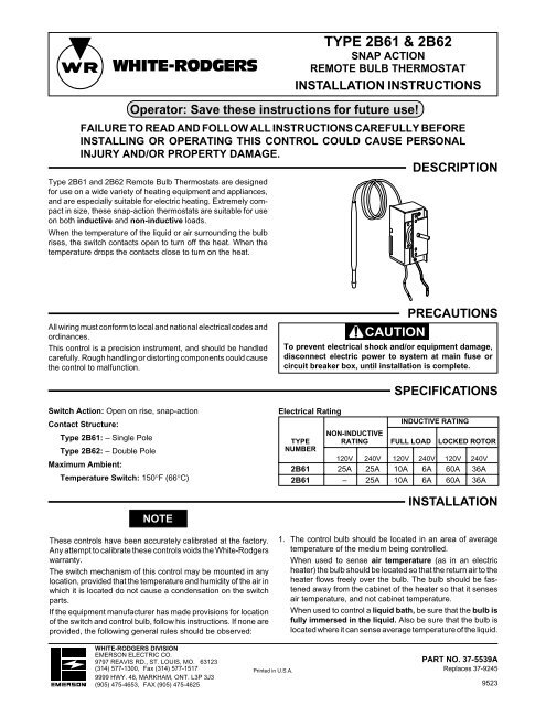
Type 2B61 and 2B62 Remote Bulb Thermostats are designed<br />
for use on a wide variety of heating equipment and appliances,<br />
and are especially suitable for electric heating. Extremely compact<br />
in size, these snap-action thermostats are suitable for use<br />
on both inductive and non-inductive loads.<br />
When the temperature of the liquid or air surrounding the bulb<br />
rises, the switch contacts open to turn off the heat. When the<br />
temperature drops the contacts close to turn on the heat.<br />
All wiring must conform to local and national electrical codes and<br />
ordinances.<br />
This control is a precision instrument, and should be handled<br />
carefully. Rough handling or distorting components could cause<br />
the control to malfunction.<br />
PRECAUTIONS<br />
CAUTION<br />
To prevent electrical shock and/or equipment damage,<br />
disconnect electric power to system at main fuse or<br />
circuit breaker box, until installation is complete.<br />
SPECIFICATIONS<br />
Switch Action: Open on rise, snap-action<br />
Contact Structure:<br />
Type 2B61: – Single Pole<br />
Type 2B62: – Double Pole<br />
Maximum Ambient:<br />
Temperature Switch: 150°F (66°C)<br />
NOTE<br />
These controls have been accurately calibrated at the factory.<br />
Any attempt to calibrate these controls voids the White-Rodgers<br />
warranty.<br />
The switch mechanism of this control may be mounted in any<br />
location, provided that the temperature and humidity of the air in<br />
which it is located do not cause a condensation on the switch<br />
parts.<br />
If the equipment manufacturer has made provisions for location<br />
of the switch and control bulb, follow his instructions. If none are<br />
provided, the following general rules should be observed:<br />
Electrical Rating<br />
INDUCTIVE RATING<br />
NON-INDUCTIVE<br />
TYPE RATING FULL LOAD LOCKED ROTOR<br />
NUMBER<br />
120V 240V 120V 240V 120V 240V<br />
2B61 25A 25A 10A 6A 60A 36A<br />
2B61 – 25A 10A 6A 60A 36A<br />
INSTALLATION<br />
1. The control bulb should be located in an area of average<br />
temperature of the medium being controlled.<br />
When used to sense air temperature (as in an electric<br />
heater) the bulb should be located so that the return air to the<br />
heater flows freely over the bulb. The bulb should be fastened<br />
away from the cabinet of the heater so that it senses<br />
air temperature, and not cabinet temperature.<br />
When used to control a liquid bath, be sure that the bulb is<br />
fully immersed in the liquid. Also be sure that the bulb is<br />
located where it can sense average temperature of the liquid.<br />
<strong>WHITE</strong>-<strong>RODGERS</strong> DIVISION<br />
EMERSON ELECTRIC CO.<br />
9797 REAVIS RD., ST. LOUIS, MO. 63123<br />
(314) 577-1300, Fax (314) 577-1517<br />
9999 HWY. 48, MARKHAM, ONT. L3P 3J3<br />
(905) 475-4653, FAX (905) 475-4625<br />
Printed in U.S.A.<br />
PART NO. 37-5539A<br />
Replaces 37-9245<br />
9523
INSTALLATION (CONT.)<br />
In this regard, do not locate the bulb too close to the heating<br />
element.<br />
2. Care should be taken not to damage the capillary tubing<br />
between the switch and bulb of the control. Do not kink the<br />
capillary.<br />
3. Do not dent or bend the control bulb as this will change the<br />
control calibration and cause the control to cycle at a temperature<br />
lower than the dial setting.<br />
4. The switch of the control may be mounted in any convenient<br />
location provided that the ambient temperature surrounding<br />
the switch does not exceed 150°F (66°C).<br />
SETTING<br />
In most cases the equipment manufacturer has provided a dial<br />
to indicate the setting of the control. For a warmer setting, turn<br />
knob or shaft clockwise. For a cooler setting, turn knob or shaft<br />
counterclockwise.<br />
WIRING<br />
All wiring should be done in accordance with local and national electrical codes and ordinances.<br />
Follow any instructions provided by the equipment manufacturer.<br />
The diagrams shown here represent typical wiring for these<br />
controls.<br />
TYPE 2B61<br />
TYPE 2B62<br />
L1<br />
BLACK (LINE)<br />
L1<br />
240V<br />
BLUE (LOAD)<br />
LINE<br />
LOAD<br />
L2<br />
L2<br />
MAKE L1 “HOT”<br />
ON 120V MODELS<br />
2
<strong>WHITE</strong>-<strong>RODGERS</strong><br />
THERMOSTAT À DÉCLIC<br />
AVEC CAPTEUR À DISTANCE<br />
TYPE 2B61 & 2B62<br />
INSTRUCTIONS D’INSTALLATION<br />
Utilisateur: conservez ces instructions pour vous y référer au besoin!<br />
SI VOUS NE LISEZ PAS ATTENTIVEMENT CES INSTRUCTIONS AVANT<br />
D’INSTALLER ET D’UTILISER LA COMMANDE, VOUS RISQUEZ DE CAUSER<br />
DES BLESSURES ET DES DOMMAGES MATÉRIELS.<br />
DESCRIPTION<br />
Les thermostats de type 2B61 et 2B62 avec capteur à distance<br />
sont conçus pour commander divers types d’appareils de<br />
chauffage et particulièrement d’appareils à l’électricité. De<br />
dimensions réduites, ces thermostats à déclic conviennent<br />
aussi bien aux charge inductives que non inductives.<br />
Lorsque la température du liquide ou de l’air en contact avec le<br />
capteur augmente, les contacts de l’interrupteur sont ouverts et<br />
coupent le chauffage. Lorsque la température baisse, les contacts<br />
sont fermés et font démarrer le chauffage.<br />
Tout le câblage doit être conforme aux codes et règlements<br />
locaux et nationaux qui régissent les installations électriques.<br />
Cette commande est un instrument de précision qui doit être<br />
manipulé avec soin. Elle peut se détraquer si elle est manipulée<br />
de façon négligente ou si des composantes sont déformées.<br />
Commutateur : Ouverture sur hause, à déclic.<br />
Contacts :<br />
Type 2B61 : Unipolaire;<br />
Type 2B62 : Bipolaire.<br />
Température ambiante maximum :<br />
Commutateur de température : 66°C (150°F)<br />
NOTE<br />
La commande a été étalonnée avec précision à l’usine. Toute<br />
tentative d’étalonnage de la commande annulera la garantie de<br />
White-Rodgers.<br />
Le commutateur de la commande peut être installé n’importe où,<br />
tant que les conditions de température et d’humidité du lieu<br />
n’entraînent pas la formation de condensation sur les composantes<br />
du commutateur.<br />
Si le fabricant de l’équipement recommande un emplacement<br />
pour la commande et le capteur, alors veuillez en tenir compte.<br />
Dans le cas contraire, veuillez vous fier aux règle générales qui<br />
suivent :<br />
PRÉCAUTIONS<br />
ATTENTION<br />
Pour prévenir les risques de chocs électriques et de<br />
dommages matériels, coupez l’alimentation du système<br />
au panneau de distribution électrique principal<br />
pendant toute la durée de l’installation.<br />
Charges électriques :<br />
SPÉCIFICATIONS<br />
CHARGE INDUCTIVE<br />
CHARGE NON PLEINE ROTOR<br />
NO DE INDUCTIVE CHARGE BLOQUÉ<br />
TYPE<br />
120 V 240 V 120 V 240 V 120 V 240 V<br />
2B61 25 A 25 A 10 A 6 A 60 A 36 A<br />
2B61 — 25A 10A 6A 60A 36A<br />
INSTALLATION<br />
1. Le capteur doit être placé dans un endroit où il sera exposé<br />
à la température moyenne du milieu à commander.<br />
S’il est utilisé pour détecter la température de l’air (comme<br />
dans un appareil de chauffage électrique), le capteur doit<br />
être placé de façon à assurer que l’air repris qui pénètre<br />
dans l’appareil puisse circuler tout autour. Le capteur doit<br />
être orienté à l’écart du boîtier afin d’assurer qu’il détecte la<br />
température de l’air et non celle du boîtier.<br />
S’il est utilisé pour détecter la température d’un bain<br />
liquide, assurez-vous que le capteur est complètement<br />
immergé. Assurez-vous aussi qu’il sera exposé à la<br />
température moyenne du liquide.<br />
<strong>WHITE</strong>-<strong>RODGERS</strong> DIVISION<br />
EMERSON ELECTRIC CO.<br />
9797 REAVIS RD., ST. LOUIS, MO. 63123<br />
(314) 577-1300, Télécopieur (314) 577-1517<br />
9999 HWY. 48, MARKHAM, ONT. L3P 3J3<br />
(905) 475-4653, Télécopieur (905) 475-4625<br />
Imprimé aux États-Unis<br />
PIÈCE NO 37-5539A<br />
Remplace 37-9245<br />
9523
INSTALLATION (suite)<br />
Ainsi, prenez soin de ne pas placer le capteur trop près de<br />
l’élément chauffant.<br />
2. Prenez soin de ne pas endommager le tube capillaire qui<br />
relie la commande au capteur. Évitez de pincer ou de plier<br />
le capillaire.<br />
3. Éviter d’écraser ou de déformer le capteur, car l’étalonnage<br />
de la commande en serait modifié. Les cycles de marche de<br />
RÉGLAGE<br />
Dans la plupart des cas, le fabricant de l’équipement fournit un<br />
cadran qui permet de régler le point de consigne de la commande.<br />
la commande prendraient alors place à une température<br />
inférieure au point de consigne.<br />
4. Le commutateur de la commande peut être installé dans<br />
n’importe quel lieu pratique où la température ambiante ne<br />
dépasse pas 66°C (150°F).<br />
Pour un hausser le point de consigne, tournez le bouton ou la<br />
tige à droite; pour le baisser, tournez à gauche.<br />
CÂBLAGE<br />
Tout le câblage doit être conforme aux codes et règlements locaux et nationaux qui régissent les installations électriques.<br />
Référez-vous aux directives fournies par le fabricant de<br />
l’équipement.<br />
Les schémas ci-dessous représentent le câblage typique des<br />
commandes.<br />
TYPE 2B61<br />
TYPE 2B62<br />
L1<br />
NOIR (RÉSEAU)<br />
240 V<br />
L1<br />
BLEU (CHARGE)<br />
RÉSEAU<br />
CHARGE<br />
L2<br />
L2<br />
MODÈLES DE 120 V :<br />
L1 DOIT ÊTRE « SOUS TENSION »<br />
2