Air Handling Unit (AHU) Controller Technical Bulletin - Engineered Air
Air Handling Unit (AHU) Controller Technical Bulletin - Engineered Air
Air Handling Unit (AHU) Controller Technical Bulletin - Engineered Air
- No tags were found...

You also want an ePaper? Increase the reach of your titles
YUMPU automatically turns print PDFs into web optimized ePapers that Google loves.
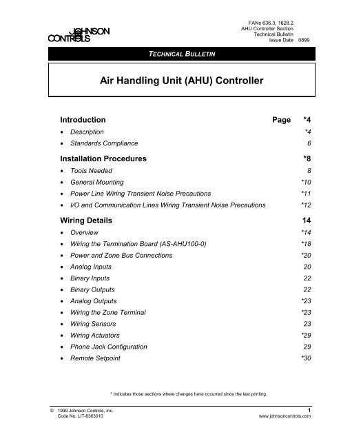
FANs 636.3, 1628.2<strong>AHU</strong> <strong>Controller</strong> Section<strong>Technical</strong> <strong>Bulletin</strong>Issue Date 0899TECHNICAL BULLETIN<strong>Air</strong> <strong>Handling</strong> <strong>Unit</strong> (<strong>AHU</strong>) <strong>Controller</strong>Introduction Page *4• Description *4• Standards Compliance 6Installation Procedures *8• Tools Needed 8• General Mounting *10• Power Line Wiring Transient Noise Precautions *11• I/O and Communication Lines Wiring Transient Noise Precautions *12Wiring Details 14• Overview *14• Wiring the Termination Board (AS-<strong>AHU</strong>100-0) *18• Power and Zone Bus Connections *20• Analog Inputs 20• Binary Inputs 22• Binary Outputs 22• Analog Outputs *23• Wiring the Zone Terminal *23• Wiring Sensors 23• Wiring Actuators *29• Phone Jack Configuration 29• Remote Setpoint *30* Indicates those sections where changes have occurred since the last printing.© 1999 Johnson Controls, Inc. 1Code No. LIT-6363010www.johnsoncontrols.com
Networking the <strong>Controller</strong> Page 32• N2 Bus Characteristics *32• Installing the N2 Bus *34• Setting the N2 Address *34• N2 Wiring to the Network Control Module *34• N2 Wiring to Companion or Facilitator *36• Zone Bus Description *37Downloading/Commissioning 38• Overview *38• Via Zone Bus *38• Via N2 Bus *38• <strong>AHU</strong> Firmware *38Troubleshooting 40• Checking the Installation 40• Tools Needed *40• HVAC PRO for Windows *42• N2 Bus Overview *44• Testing the N2 Bus *45Configuring the <strong>Controller</strong> 48• Using HVAC PRO for Windows Configuration Tool *48• Defining an <strong>AHU</strong> Control Device Object in Metasys Software *49• Defining an <strong>AHU</strong> Control Device in Companion/Facilitator Software *51Ordering Information 52• Johnson Controls Code Numbers *52• Vendor Code Numbers *54Specifications *56Appendix A: <strong>AHU</strong> Tower *58• Tower Installation *602 <strong>AHU</strong> <strong>Controller</strong>—<strong>Air</strong> <strong>Handling</strong> <strong>Unit</strong> (<strong>AHU</strong>) <strong>Controller</strong>
* Indicates those sections where changes have occurred since the last printing.<strong>AHU</strong> <strong>Controller</strong>—<strong>Air</strong> <strong>Handling</strong> <strong>Unit</strong> <strong>Controller</strong> (<strong>AHU</strong>) 3
IntroductionIn this document, Facility Management System (FMS) is a generic termthat refers to the Metasys® Network, Companion, and Facilitatorsupervisory systems. The specific system names are used when referring tosystem-specific applications.Table 1: Related DocumentsDocument TitleASC and N2 Bus Networking andTroubleshooting Guide <strong>Technical</strong> <strong>Bulletin</strong><strong>Controller</strong> and N2 Bus Networking andTroubleshooting Guide <strong>Technical</strong> <strong>Bulletin</strong>CodeNumberFANLIT-6363003 636.3LIT-1628310 1628.2Auxiliary Gear <strong>Technical</strong> <strong>Bulletin</strong> LIT-6363080 636.3N2 Communications Bus <strong>Technical</strong> <strong>Bulletin</strong><strong>Unit</strong>ary (UNT) <strong>Controller</strong> <strong>Technical</strong> <strong>Bulletin</strong>Universal Packaging Module <strong>Technical</strong> <strong>Bulletin</strong>LIT-636018LIT-6281120LIT-1628120LIT-6363081LIT-1628320LIT-6363070LIT-16283701628.2636628.11628.1636.31628.2636.31628.2DescriptionThe Johnson Controls <strong>Air</strong> <strong>Handling</strong> <strong>Unit</strong> (<strong>AHU</strong>) <strong>Controller</strong> is a completedigital control system for most common air handling configurations,including single zone, variable air volume, multi-zone, and dual duct. Youmay use the <strong>AHU</strong> as a standalone controller or connected to a FMS.When connected to the FMS, the <strong>AHU</strong> provides all point and controlinformation to the rest of the network. The devices communicate throughan Opto-22® RS-485 N2 Bus.Each <strong>AHU</strong> application uses a different sequence of operation, all of whichare covered in the HVAC PRO for Windows User’s Manual (FAN 637.5or 1637.5).PackagingThe <strong>AHU</strong> is available in the following packaging configurations:●●<strong>AHU</strong>103 in a triple UPM ( Universal Packaging Module) enclosure(EWC35) with special <strong>AHU</strong> door<strong>AHU</strong>102 individual controller board combined with the <strong>AHU</strong>100individual termination board4 <strong>AHU</strong> <strong>Controller</strong>—<strong>Air</strong> <strong>Handling</strong> <strong>Unit</strong> (<strong>AHU</strong>) <strong>Controller</strong>
Note:Johnson Controls Poteau Panel <strong>Unit</strong> facility can lay out, mount,and wire these enclosures to your requirements. Contact the PoteauPanel <strong>Unit</strong> at (918) 647-2195.Low VoltageWiring ConduitLine VoltageConduit from120 VAC Supply<strong>AHU</strong>100TerminationBoard<strong>AHU</strong>102<strong>Controller</strong>BoardPower Supply/TransformerRelayModuleFM KitZoneTerminal<strong>AHU</strong>103Figure 1: <strong>AHU</strong>103 Example<strong>AHU</strong>103The <strong>AHU</strong>103 consists of an <strong>AHU</strong>100-0 termination board, an <strong>AHU</strong>102controller board, and a 92 VA transformer, packaged in a 3-high UniversalPackaging Module (UPM). For details of the footprint and interiordimensions of the UPMs, refer to the Universal Packaging Module<strong>Technical</strong> <strong>Bulletin</strong> (LIT-6363070) in the Metasys Applications Specific<strong>Controller</strong>s <strong>Technical</strong> Manual (FAN 636.3) or Universal PackagingModule <strong>Technical</strong> <strong>Bulletin</strong> (LIT-1628370) in the Facilitator ApplicationSpecific <strong>Controller</strong>s <strong>Technical</strong> Manual (FAN 1628.2). You can add UPMsto expand enclosure space. Refer to the Ordering Information section ofthis document for a listing of the appropriate part numbers.<strong>AHU</strong> <strong>Controller</strong>—<strong>Air</strong> <strong>Handling</strong> <strong>Unit</strong> <strong>Controller</strong> (<strong>AHU</strong>) 5
<strong>AHU</strong> TowerThe <strong>AHU</strong> Tower (Figure 26) configuration has been discontinued.For information about the tower configuration, refer to Appendix A:<strong>AHU</strong> Tower at the end of this document.Table 2: <strong>AHU</strong> Model FeaturesFeature AS-<strong>AHU</strong>103-300 or FA-<strong>AHU</strong>103-300 *Ambient Temperature Rating 0 to 50°C(32 to 122°F)Analog Inputs 8RTD temperature elements (1000 ohm nickel,platinum, or silicon)2k ohm setpoint potentiometers0 to 10 VDC or 0 to 2 VDC transmitters0-20 mABinary Inputs 8Dry contacts0 to 15 VDC(2.5 VDC trigger)Analog Outputs 60/2 to 10 VDC, 0/4-20 mABinary Outputs 1024 VAC triacs switched50-500 mA loadsN2 BusZone BusIsolatedDiscrete connections at controller8-pin and 6-pin phone jacks on controller24 VAC Power Terminations J4 - 3-pin Molex to AS-XFR100I/O TerminationsN2 TerminationsScrew terminal (plug-in optional)Fixed screw terminal block*AS indicates Metasys and FA indicates Facilitator.StandardsComplianceThe <strong>AHU</strong> complies with the following standards:●FCC Part 15, Subpart J, Class A● IEEE 446, IEEE 472, IEEE 518●●●IEEE 587 Category A/BUL 916 SafetyUL 864 Smoke Control● CSA C22.2 No. 2056 <strong>AHU</strong> <strong>Controller</strong>—<strong>Air</strong> <strong>Handling</strong> <strong>Unit</strong> (<strong>AHU</strong>) <strong>Controller</strong>
<strong>AHU</strong> <strong>Controller</strong>—<strong>Air</strong> <strong>Handling</strong> <strong>Unit</strong> <strong>Controller</strong> (<strong>AHU</strong>) 7
Installation ProceduresApplication Specific <strong>Controller</strong>s (ASCs) are Direct Digital <strong>Controller</strong>s youconfigure for unique HVAC applications using HVAC PRO forWindows. The type and number of components (sensors and actuators)selected for use with the <strong>AHU</strong> varies according to application. Analyze theproposed installation for logical location of these devices and draw up aninventory based on that study. Information on types of accessory devices isavailable in the Ordering Information section of this document.Tools NeededTools needed for a typical installation include:●●●●●1/4 inch boltsNo. 8 Plastite screws [for maximum holding power of 90.7 kg(200 lb)].Note: No. 8 sheet metal screws, type A or AB are an alternative.However, these screws have a maximum holding power of45.3 kg (100 lb).wrench and screwdriver appropriate to the bolt and screw headsTorx® screwdriver for T-20 recessed screws (needed for expandingthe enclosure)drill8 <strong>AHU</strong> <strong>Controller</strong>—<strong>Air</strong> <strong>Handling</strong> <strong>Unit</strong> (<strong>AHU</strong>) <strong>Controller</strong>
ProximityEnvironmentIn the interest of efficiency, decide how close the <strong>AHU</strong> can be located tothe air handling equipment—with adequate mounting surfaces, andreasonable access to installation and maintenance workers. Determiningthe location for the <strong>AHU</strong> depends on the existence of power sources andcommunication lines, and on which power sources and communicationlines are to be used. The <strong>AHU</strong> must be secured to a solid wall and not toany vibrating surface.Select a wall space or area with sufficient room to mount the enclosuresand install conduits. The load-bearing capacity of the wall must be able tosupport the full configuration weight. Wood surfaces generally onlyrequire bolting the enclosure to the wall; dry wall surfaces require anchorsfor the bolts.Due to the rigidity and strength of the molded plastic enclosure, the weightsupported by an individual UPM section is probably higher than anyapplication requirement. The pull-out value of the screw holes on theUPM backbone is 90.7 kg (200 lb). However, in securing a very heavyobject, the best practice is to distribute the weight over a number ofscrews.The weight resting on the bottom endcap must not exceed 22.6 kg (50 lb).The installation site of the <strong>AHU</strong> must meet the following environmentalstandards:●●●●●The atmosphere must be free of explosive vapors or escaping gases.The atmosphere must be free of exposure to corrosive chemical or saltvapors that might damage electrical equipment.The temperature must be maintained between 0 to 50°C (32 to 122°F)with the relative humidity (non-condensing) maintained between10 and 90 percent.The 120 VAC split-bobbin transformer (XFR) in the UPM providestransient immunity. Split-bobbin transformers have primary andsecondary coils on separate, side-by-side bobbins. The power must be“clean” without electrical noise transients that are often present inindustrial environments; otherwise, Metal Oxide Varistors (MOVs)must be added to the primary wires. Commercial and residentialbuildings typically have “clean” power, but may not, depending on thelocation, nearby equipment, etc. Refer to the Power Line WiringTransient Noise Precautions section of this document.The UPM is for indoor use only. Avoid areas where water leakage mayoccur.<strong>AHU</strong> <strong>Controller</strong>—<strong>Air</strong> <strong>Handling</strong> <strong>Unit</strong> <strong>Controller</strong> (<strong>AHU</strong>) 9
GeneralMountingWindowExpansion KitExpansion KitOptionAdding Sectionsto Existing <strong>Unit</strong>sFunctionModule Kit(AS-FMK102-0)The controller requires a mounting surface area to match its dimensions:337.8 x 200.66 x 175.26 mm (13.3 x 7.9 x 6.9 in.)Follow the steps below when mounting an enclosure:1. Remove the cover (hinged on the left side) by opening it to a 90°angle and lifting it up and away.2. Position the unit on the wall and mark the mounting slot location.3. Drill a hole to accommodate a 1/4-inch bolt. Install the bolt, leaving3/8 inch to 1/2 inch of thread exposed to hang the unit on.4. Hang the backbone over the bolt. Plumb the box. Mark theappropriate mounting holes along the wiring channels.5. Drill into the wall to accommodate the mounting holes (the units canbe left in place or removed from the wall). Secure the unit with1/4-inch bolts.6. Mount the gear, using the No. 8 screws (seating torque should be25 lb•in minimum) and replace the door.For those who want to monitor equipment such as gauges and LEDs(Light-Emitting Diodes), an optional full-window cover provides easyviewing while keeping the equipment securely locked away fromunauthorized users. The Window Expansion Kit (EN-WIN101-0) includesa full-window cover, a backbone, and T-20 Torx screws (for fasteningsections together).The Expansion Kit option provides additional storage capacity forequipment that does not need to be viewed. The Expansion Kit(EN-EXP101-0) includes a solid cover, a backbone, and T-20 Torx screws(for fastening sections together). You can order this kit to expand anexisting enclosure at the job site or as part of an original configurationthrough the Johnson Controls Panel <strong>Unit</strong>.You may add a backbone and cover to the bottom of an existing unitwithout having to rewire the original controls.The Function Module Kit (FMK) provides the enclosure and terminationboard to connect up to four, single-slot function modules to the <strong>AHU</strong>. Formore information on the use of the FMK, refer to the Auxiliary Gear<strong>Technical</strong> <strong>Bulletin</strong> (LIT-6363080) in FAN 636.3 or 1628.2.10 <strong>AHU</strong> <strong>Controller</strong>—<strong>Air</strong> <strong>Handling</strong> <strong>Unit</strong> (<strong>AHU</strong>) <strong>Controller</strong>
Relay Module(AS-RLY002-0)Power LineWiringTransientNoisePrecautionsThe relay module is a self-contained relay device that provides an interfacebetween the low voltage circuitry and line-voltage devices. Install the RLYin the desired location near the line-voltage wiring in the UPM. Positionthe RLY002 so the terminal for relay contacts is adjacent to the linevoltagewiring in the UPM. For more information on the use of the RLY,refer to the Auxiliary Gear <strong>Technical</strong> <strong>Bulletin</strong> (LIT-6363080) in FAN636.3 or 1628.2.The standard <strong>AHU</strong>, when powered by a split-bobbin transformer(XFR100) operates reliably in an electrical environment defined asLocation Category “A” or “B” by the IEEE 587 Standard:●IEEE 587 Location Category “A” power line surge/noise level isspecified at 6 kV, 500 A (Ringwave).● IEEE 587 Location Category “B” power line surge/noise level isspecified at 6 kV, 3000 A (Ringwave and Exponential Wave).For more information on noise prevention, refer to Appendix A:Precautions for Rooftop Installations section of the <strong>Unit</strong>ary (UNT)<strong>Controller</strong> <strong>Technical</strong> <strong>Bulletin</strong> in FAN 636.3 or 1628.2.A B CA B CPLWTFigure 2: Location Categories<strong>AHU</strong> <strong>Controller</strong>—<strong>Air</strong> <strong>Handling</strong> <strong>Unit</strong> <strong>Controller</strong> (<strong>AHU</strong>) 11
I/O andCommunicationLines WiringTransient NoisePrecautionsThe I/O wiring and N2 Bus must be clean, without electrical noisetransients from nearby lighting, heavy equipment switching, or inductiveloads being driven. For more information on noise prevention, refer toAppendix A: Precautions for Rooftop Installations in the <strong>Unit</strong>ary (UNT)<strong>Controller</strong> <strong>Technical</strong> <strong>Bulletin</strong> in FAN 636.3 or 1628.2.In general, a proper <strong>AHU</strong> installation does not require a suppressiondevice. If noise problems are encountered, identify the offending devicesand install suppression devices. For example, the switching of inductiveloads can generate transients that can be conducted and/or radiated into thecircuits controlling those loads, as well as into other circuits nearby.For inductive loads, the recommended suppression device is theACC-22-0 for 12 to 120 VAC. For the N2 Bus, the recommendedsuppression device is the Transient Eliminator®, model TE/JC04C12,made by Advanced Protection Technologies (APT). For more information,refer to the N2 Communications Bus <strong>Technical</strong> <strong>Bulletin</strong> in FAN 636,628.1, or 1628.1.Besides these recommended devices, you may find a different device thathas the same capabilities. The device must meet or exceed thespecifications in Table 3, which were derived from Metal Oxide Varistors(MOVs).Table 3: Specifications for Suppression Devices (MOVs)Load Voltage24 VAC 120 VAC 208-240 VAC 277 VAC 347 VACMinimumContinuousVoltageRatingMinimumEnergy RatingMinimumPeak Current(8 x 20microsecondpulse)ULRecognized30 VRMS 130-135VRMS250-280VRMS320 VRMS 385VRMS8.5 Joules 30 Joules 55 Joules 80 Joules 85 Joules1000Amperes4000Amperes4000Amperes4000Amperes4000AmperesOptional Required Required Required RequiredThe most effective location for the suppression device is at the load, sinceit lessens the propagation of transient energy into connected wiring which,in turn, becomes a source of noise to adjacent wiring. Difficulties ingetting access to the load, however, may sometimes make it necessary tolocate the suppression device at the <strong>AHU</strong>.12 <strong>AHU</strong> <strong>Controller</strong>—<strong>Air</strong> <strong>Handling</strong> <strong>Unit</strong> (<strong>AHU</strong>) <strong>Controller</strong>
<strong>AHU</strong> <strong>Controller</strong>—<strong>Air</strong> <strong>Handling</strong> <strong>Unit</strong> <strong>Controller</strong> (<strong>AHU</strong>) 13
Wiring DetailsOverviewYou need to take special precautions and follow certain groundingprocedures when installing the <strong>AHU</strong>.!CAUTION: Possible Equipment Damage or Electrical Shock.To avoid damaging equipment or electrical shock,ensure that all power supplies to the system have beendisconnected prior to wiring installation. The circuitsused in the controller are static sensitive. Use staticprotection (anti-static mats and/or grounding straps) ortouch conduit ground before touching circuit boardswhen working on or near internal circuitry.Follow these precautions:●●●●●●Make all wiring connections in accordance with the National ElectricalCode (NEC) as well as with local regulations.The N2 Bus and signal wiring must be a twisted pair due to electricfield and magnetic coupling. Locate equipment and route the N2 Busand signal wiring so they are separated from power wiring by aminimum of one foot (two is preferred). If power wiring is in agrounded steel conduit, then the <strong>AHU</strong> and N2 signal wiring can beplaced next to the conduit.Do not run N2 Bus and field wiring in the same conduit as line-voltagewiring (30 VAC or higher) or near wiring that switches power to highlyinductive loads (such as contactors, coils, motors, or generators).Make all wiring connections to the <strong>AHU</strong> using only copper conductorsof 24 to 18 AWG.The N2 must be daisy-chained without “Y” or “T” connections unlessN2 repeaters are used. Refer to the ASC and N2 Bus Networking andTroubleshooting Guide <strong>Technical</strong> <strong>Bulletin</strong> in FAN 636.3 or <strong>Controller</strong>and N2 Bus Networking and Troubleshooting Guide <strong>Technical</strong><strong>Bulletin</strong> in FAN 1628.2.Use the recommended suppression devices on inductive loads, such asV11 solenoids and contactors/starters.14 <strong>AHU</strong> <strong>Controller</strong>—<strong>Air</strong> <strong>Handling</strong> <strong>Unit</strong> (<strong>AHU</strong>) <strong>Controller</strong>
● Isolate all commons on the controller from earth ground, including the24 VAC power supply.• Shielded cable is not required for field wiring, but when used, hardground the shield at the UPM enclosure and tape it back at the sensoror contact.Power Box andTransformerLocationLanding ConduitThe power box and transformer can be located in different areas of theenclosure, depending on the requirements of the other installed equipment.There are four discrete locations for the power box, designated as A, B, C,or D on the outside of the endcap of the UPM enclosure. The power box isgenerally located in Area C. Set the power box on the inside of the unitover two bosses corresponding to one of the locations; A, B, C, or D.Position the transformer to within 12.7 mm (1/2 inch) of the power box.Note: You must reconnect the ground wires if you move the power box.We recommend that you use a hole-punch bit, or Greenlee® punch whendrilling conduit holes.!CAUTION: Equipment Damage Hazard. Do not use a spade bitto drill conduit holes. Using a spade bit damages theground plane.Top EntryThere are four 3-inch by 3-inch areas designated A, B, C, or D on theoutside of the endcap for conduit entry into the power box. After notingthe location of the power box, drill or punch a hole in the selected area toland the conduit.A B C DCOVERFigure 3: Line-Voltage Conduit Entry from the Top of the Enclosure<strong>AHU</strong> <strong>Controller</strong>—<strong>Air</strong> <strong>Handling</strong> <strong>Unit</strong> <strong>Controller</strong> (<strong>AHU</strong>) 15
Side EntryA “guide” groove has been molded onto each side of the backbone sectionto help locate a drill point. Drill or punch a hole in the groove at the pointthat lines up with the conduit at the end of the enclosure.FrontDrill PointLocationBLWUPSDFigure 4: Line-Voltage Conduit Entry from the SidePowerConnectionsGrounding andBondingUse wire nuts to connect the power source hot and neutral lines to thecorresponding lines inside the power box. Use wire nuts to connect thepower source ground wire to the green power box wire. This grounds thepower outlets (which are internally connected to a ring terminal on thegrounding screw). The transformer is already connected to the secondring terminal on the same grounding screw.This connection completes the line-voltage wiring to the power outlets andthe transformer. Internal connections to power outlets, switch, and groundare made at the factory. Switches control power to the transformer.Installing the power box in any of the four designated positions locates oneof the rear slots of the box over a grounding screw at the back of theendcap (each endcap has two grounding screws). The power box must bereferenced (grounded) to a green-wire earth ground.16 <strong>AHU</strong> <strong>Controller</strong>—<strong>Air</strong> <strong>Handling</strong> <strong>Unit</strong> (<strong>AHU</strong>) <strong>Controller</strong>
When bringing multiple conduits into one end of the enclosure, thestandard conduit connectors automatically connect to the ground plane,grounding all conduits together. Attaching other devices to the oppositescrew on the same endcap also grounds those devices via the aluminumground plane.To electrically bond the second endcap to the grounded endcap, attach aground wire from the open screw of the power box endcap to either of thegrounding screws of the second endcap.Table 4: Wire Selection GuideIncoming Service15 Ampere 14 AWG minimum (1.628 mm diameter)20 Ampere 12 AWG minimum (2.053 mm diameter)30 Ampere 10 AWG minimum (2.588 mm diameter)Ground Wireupmnt3Figure 5: Power and Grounding/Bonding Terminations!WARNING: It is extremely important to separate line-voltagewiring and control/low voltage wiring and circuitryby a minimum of one inch. If this condition is notmet, the installation may not comply with localcode requirements.<strong>AHU</strong> <strong>Controller</strong>—<strong>Air</strong> <strong>Handling</strong> <strong>Unit</strong> <strong>Controller</strong> (<strong>AHU</strong>) 17
Wiring theTerminationBoard(AS-<strong>AHU</strong>100-0)The <strong>AHU</strong> terminal designations that identify sensor and actuatorconnection points are illustrated below. Terminal functions are listed inTable 5. Use the HVAC PRO for Windows Configuration Tool to assignthe inputs and outputs for a specific application.Not forPower Connection11 VA Maximum OutputPower LEDZone BusN2 BusBinaryOutputs24 VACTriacsAnalogOutputs0-20 mABinaryInputsDry Contact0-15 VDCAnalogInputsVoltage,Current,Resistance24ACCOMZBUSN2A+N2A-AREFBO 124ACBO 2BO 324ACBO 4BO 524VBO 6BO 724ACBO 8BO 924ACBO 10+AO 1-AOCM+AO 2+AO 3-AOCM+AO 4+AO 5-AOCM+AO 6BI 1BICMBI 2BI 3BICMBI 4BI 5BICMBI 6BI 7BICMBI 8+VDC+AI 1-AICOM+AI 2+AI 3-AICM+AI 4+AI 5-AICM+AI 6+AI 7-AICM+AI 8+VDC1234567891011121314151617181920212223242526272829303132333435363738394041424344454647484950515253545556DS1 +30 VDCOUTJ1J2J3J5J6J7J8J9J11J13J14J15XFR1J4To RLYTo FMK6 PinJ10J128 PinTo FMK24 VACTransformerPower InputUpahuboard<strong>AHU</strong>102ConnectsHereFigure 6: <strong>AHU</strong>100 Terminal Assignments18 <strong>AHU</strong> <strong>Controller</strong>—<strong>Air</strong> <strong>Handling</strong> <strong>Unit</strong> (<strong>AHU</strong>) <strong>Controller</strong>
Table 5: <strong>AHU</strong>100 Terminal IdentificationTerminal No. Description Terminal No. Description24 AC 1 24 VAC for Zone BusOnly-AOCOM 29 Analog OutputCommonCOM 2 Common +AO 6 30 Analog Output 6ZBUS 3 Zone Bus BI 1 31 Binary Input 1N2A+ 4 N2 Bus + BICM 32 Binary InputCommonN2A- 5 N2 Bus - BI 2 33 Binary Input 2AREF 6 N2 Reference BI 3 34 Binary Input 3BO 1 7 Binary Output 1 BICM 35 Binary InputCommon24 AC 8 24 VAC BI 4 36 Binary Input 4BO 2 9 Binary Output 2 BI 5 37 Binary Input 5BO 3 10 Binary Output 3 BICM 38 Binary InputCommon24 AC 11 24 VAC BI 6 39 Binary Input 6BO 4 12 Binary Output 4 BI 7 40 AccumulatorBO5 13 Binary Output 5 BICM 41 Binary InputCommon24 AC 14 24 VAC BI 8 42 AccumulatorBO 6 15 Binary Output 6 +VDC 43 + 30 VDC forTransducersBO7 16 Binary Output 7 +AI 1 44 Analog Input 124 AC 17 24 VAC -AICOM 45 Analog InputCommonBO 8 18 Binary Output 8 +AI 2 46 Analog Input 2BO 9 19 Binary Output 9 +AI 3 47 Analog Input 324 AC 20 24 VAC -AICOM 48 Analog InputCommonBO 10 21 Binary Output 10 +AI 4 49 Analog Input 4+AO 1 22 Analog Output 1 +AI 5 50 Analog Input 5-AOCOM 23 Analog OutputCommon-AICOM 51 Analog InputCommon+AO 2 24 Analog Output 2 +AI 6 52 Analog Input 6+AO 3 25 Analog Output 3 +AI 7 53 Analog Input 7-AOCOM 26 Analog OutputCommon-AICOM 54 Analog InputCommon+AO 4 27 Analog Output 4 +AI 8 55 Analog Input 8+AO 5 28 Analog Output 5 +VDC 56 + 30 VDC forTransducers<strong>AHU</strong> <strong>Controller</strong>—<strong>Air</strong> <strong>Handling</strong> <strong>Unit</strong> <strong>Controller</strong> (<strong>AHU</strong>) 19
Make connections to the <strong>AHU</strong> in one of two ways:●●either connect single wires to the individual screw terminalsor, for Analog Inputs (AI), Analog Outputs (AO), and Binary Outputs(BO) within 36 inches of the controller, plug an AS-CBL100-0Connector into the appropriate terminals between the controller andthe relay enclosure, or function module kit.Power andZone BusConnectionsAnalog Inputs24 VAC input to the <strong>AHU</strong>100 plugs into the Molex connector (J4). Thisconnector has a built-in line filter. Do not connect power to screwTerminals 1 and 2. This is filtered power out to Zone Bus devices.Zone Bus may be hard-wired to the <strong>AHU</strong> instead of using the phone jackas described later in this technical bulletin. Terminal 3 (Figure 6) links thecontroller with Zone Bus. The Zone Bus provides 24 VAC, Common, andZBUS. Terminals 1 and 2 are limited to 11 VA at 24 VAC.The <strong>AHU</strong> controls input/output devices on the Zone Bus (e.g., six MasterM100C series motors with unlimited slaves), the ZT, and laptop.The eight Analog Input (AI) terminals, their power supply, and theircommon points occupy Positions 43 through 56 of the terminal strip.These inputs may be of three types: resistive, voltage, or current. The<strong>AHU</strong>102 Logic Board processes and controls the configured controlstrategy. It reads the analog inputs through the analog input jumperslocated on the lower right of the board. The type of analog input is selectedthrough these jumpers (Figure 8). Table 6 shows each configuration.Table 6: Jumper Configurations on <strong>AHU</strong>102AI TypeRangeCurrent (C)Voltage (V)Resistance (T) Temperature0-20 mA, 4-20 mA0-10 VDC, 0-5 VDC, 1-5 VDC1,000 ohm Nickel, Platinum, or Silicon, 0-2K ohmpotentiometerNote:The <strong>AHU</strong> constantly resets if the jumper setting is voltage (V) ortemperature (T) and the input signal is current. To correct thiscondition, set the AI jumper to the “C” position for the currentinput channel.20 <strong>AHU</strong> <strong>Controller</strong>—<strong>Air</strong> <strong>Handling</strong> <strong>Unit</strong> (<strong>AHU</strong>) <strong>Controller</strong>
+VDC0.001MicrofaradsAI-10.001Microfarads5J11To24 VACTo<strong>AHU</strong>1021AI COM0.001MicrofaradsAI-20.001Microfarads<strong>AHU</strong>101-1Figure 7: <strong>AHU</strong>100 Analog Input Wiring Diagram for CBL100<strong>AHU</strong> <strong>Controller</strong>—<strong>Air</strong> <strong>Handling</strong> <strong>Unit</strong> <strong>Controller</strong> (<strong>AHU</strong>) 21
Figure 8 shows N2 hardware address switches and AI jumper positions.Use these switches to set the N2 Bus address. Boards without this switchmust have the N2 address set through the HVAC PRO for WindowsConfiguration Tool.T V CAnalog InputJumpersT V CT V CT V CT V CCurrentInputN2 Address128 64 32 16 8 4 2 1T V CT V CT V CT V CT V CT V CTemperatureInputVoltageInput=Address 17128 64 32 16 8 4 2 1128 64 32 16 8 4 2 1<strong>AHU</strong>JMPFigure 8: N2 Address SwitchesBinary InputsBinary OutputsThe eight Binary Input (BI) terminals and their common points occupyPositions 31 through 42 of the terminal strip. These inputs are of the drycontact type or 0 to 15 volt range with 2.5 VDC TTL thresholds.The ten Binary Output (BO) terminals and their 24 VAC points occupyPositions 7 through 21 of the terminal strip. Binary outputs are triacs onthe controller hardware that can be directly connected to 24 VAC relays orsolenoids. The binary outputs switch the common side of the powertransformer (50 mA minimum to 500 mA maximum).22 <strong>AHU</strong> <strong>Controller</strong>—<strong>Air</strong> <strong>Handling</strong> <strong>Unit</strong> (<strong>AHU</strong>) <strong>Controller</strong>
Analog OutputsThe six Analog Output (AO) terminals and their common points occupyPositions 22 through 30 of the terminal strip. Analog outputs may be eithera current (0/4 to 20 mA), or with a 499 ohm (1/2-watt) resistor, a voltage(0/2 to 10 VDC).IMPORTANT:When connecting to Variable Frequency Drives, whichare typically earth grounded, use 4-20 mA isolators.Zone BusWiring theZone TerminalWiring SensorsThe Zone Bus allows you to connect an AS-CBLPRO-2 or the ZoneTerminal to the <strong>AHU</strong>. With AS-CBLPRO-2 connected, use HVAC PROfor Windows for commissioning, downloading, and uploading. TheZone Bus is available for connections at a zone temperature sensor 6-pinand 8-pin phone jack.For detailed information regarding wiring the Zone Terminal, refer to theZone Terminal <strong>Technical</strong> <strong>Bulletin</strong> (LIT-636014 or LIT-1628330) inFAN 636.3 or FAN 1628.2.Use 18 AWG (1.5 mm 2 ) twisted pair for all sensor and output wiring.Shielding is not required, but if used, earth ground the shield at the AS-XFR or the AS-RLY box. Use of 24 AWG (0.6 mm) wire may be desiredin some applications; however, the recommended length of wire is reduceddue to the resistance. To minimize sensor error caused by field wiring, thetotal resistive sensor wiring should be less than three ohms.<strong>AHU</strong> <strong>Controller</strong>—<strong>Air</strong> <strong>Handling</strong> <strong>Unit</strong> <strong>Controller</strong> (<strong>AHU</strong>) 23
The M100C Actuator requires a separate24 VAC transformer.Not for power connection;11 VA maximum output.Supervisory<strong>Controller</strong>Performs like avariable resistor.+N2-N2N2 REFN2 Bus ispolarity sensitive.Daisy chain+N2 to +N2, etc.24 VAC is always present at the load.The common side at the BO terminalis switched On and Off.IAP or IDPM100CDon't reverse the wires on IAPs or IDPs.If you do, 30 VDC will be applied to anAI terminal, which will burn out a 100 ohm resistor.T224 VAC24 VAC Solenoidor RelayLoadPSI 102OAP10320-30 VDCOUTTE24ACCOMZBUSN2A+N2A-AREFBO 124ACBO 2BO 324ACBO 4BO 524VBO 6BO 724ACBO 8BO 924ACBO 10+AO 1-AOCM+AO 2+AO 3-AOCM+AO 4+AO 5-AOCM+AO 6BI 1BICMBI 2BI 3BICMBI 4BI 5BICMBI 6BI 7BICMBI 8+VDC+AI 1-AICOM+AI 2+AI 3-AICM+AI 4+AI 5-AICM+AI 6+AI 7-AICM+AI 8+VDC123DS1 +456789J1XFR1101112J213J414 J315 24 VAC T11617 J51819XFR100TRIAC20 J6 COM21222324J72526 J8272829 J9303132333435363738394041 J106-pin4243 30 VDCOUT4445 J1246 J1147 8-pin4849J13"C"505152J14535455J15 1005630 VDC Out COMUpCOMPWR12-30 VDCHE 6300/6310ahulayotFigure 9: Wiring Sensors24 <strong>AHU</strong> <strong>Controller</strong>—<strong>Air</strong> <strong>Handling</strong> <strong>Unit</strong> (<strong>AHU</strong>) <strong>Controller</strong>
!CAUTION: Possible Equipment Damage. Do not run sensorwiring near line-voltage wiring.Table 7: ASC Wiring GuideSensor TypeAI Temperature(Resistive)18 AWG Wire Size RunLength in Meters(Feet)24 AWG Wire Size RunLength in Meters(Feet)152.4 (500) 30.5 (100)AI Voltage 152.4 (500) 30.5 (100)AI Current 304.8 (1000) 304.8 (1000)AO Voltage/Current(See note below.)304.8 (1000) 304.8 (1000)BI Voltage/Contact 152.4 (500) 152.4 (500)Single BO at 0.1 ampere 152.4 (500) 30.5 (100)Single BO at 0.5 ampere 30.5 (100) 6.1 (20)Multiple BOs UsingRLY100/050/002152.4 (500) 30.5 (100)Zone Bus 152.4 (500) 15.2 (50)24 VAC Power(AS-XFR)20 VDC to 30 VDC PowerSupply @ 160 mA(<strong>AHU</strong> only)15 VDC Power Supply @90 mA (VAV, UNT only)15 VDC Power Supply @200 mA (DX only)1.5 (5) N/A1000 (304.8) 200 (61.0)1000 (304.8) 200 (61.0)1000 (304.8) 200 (61.0)Note:For AO voltage, place resistor at the end of the line at the actuatoror variable speed drive. Use a 499 ohm ± 1% 1/2-watt resistor for0-10 VDC, or a 249 ohm ± 1% 1/2-watt resistor for 0-5 VDC.<strong>AHU</strong> <strong>Controller</strong>—<strong>Air</strong> <strong>Handling</strong> <strong>Unit</strong> <strong>Controller</strong> (<strong>AHU</strong>) 25
Humidity SensorConnectionHE-6310Note:The output voltage selectionfor the HE-6310 is 0 to 10 V.24ACCOMZBUSN2A+N2A-AREFBO 124VBO 2BO 324VBO 4BO 524VBO 6BO 724VBO 8BO 924VBO 10AO 1AOCOMAO 2AO 3AOCOMAO 4AO 5AOCOMAO 6BI 1BICOMBI 2BI 3BICOMBI 4BI 5BICOMBI 6BI 7BICOMBI 8+VDCAI 1AICOMAI 2AI 3AICOMAI 4AI 5AICOMAI 6AI 7AICOMAI 8+VDCAI6-Set jumperto "T."AI8-Set jumper to "V."43444546474849505152535455561234567891011121314151617181920212223242526272829303132333435363738394041424344454647484950515253545556+VDCAI 1AICOMAI 2AI 3AICOMAI 4AI 5AICOMAI 6AI 7AICOMAI 8+VDCahuapplFigure 10: Example of HE-6310 Humidity Sensor Connectionto <strong>AHU</strong>To connect a humidity sensor:1. Set the analog input jumper on the ASC <strong>Controller</strong> Board toV (voltage) for the humidity input. Set the temperature input toT (temperature).2. Enter the range of the humidity sensor through HVAC PRO forWindows software (0 to 10 VDC is equal to 0-100% RH).26 <strong>AHU</strong> <strong>Controller</strong>—<strong>Air</strong> <strong>Handling</strong> <strong>Unit</strong> (<strong>AHU</strong>) <strong>Controller</strong>
Screw TerminalTE-6400TemperatureSensor148 5567214324ACCOMZBUSN2A+N2A-AREFBO 124VBO 2BO 324VBO 4BO 524VBO 6BO 724VBO 8BO 924VBO 10AO 1AOCOMAO 2AO 3AOCOMAO 4AO 5AOCOMAO 6BI 1BICOMBI 2BI 3BICOMBI 4BI 5BICOMBI 6BI 7BICOMBI 8+VDCAI 1AICOMAI 2AI 3AICOMAI 4AI 5AICOMAI 6AI 7AICOMAI 8+VDC1234567891011121314151617181920212223242526272829303132333435363738394041424344454647484950515253545556TE-6400BFigure 11: TE-6400 Screw Terminals<strong>AHU</strong> <strong>Controller</strong>—<strong>Air</strong> <strong>Handling</strong> <strong>Unit</strong> <strong>Controller</strong> (<strong>AHU</strong>) 27
Sharing aSensorTE - 6100Outdoor <strong>Air</strong> Sensor<strong>AHU</strong>1VDCAI 1AICOMAI 2AI 3AS-<strong>AHU</strong>100-0AS-<strong>AHU</strong>102 JumperSettingVT C(T Position)<strong>AHU</strong>2VDCAI 1AICOMAI 2AI 3AS-<strong>AHU</strong>100-0AS-<strong>AHU</strong>102 JumperSettingVT C(V Position)<strong>AHU</strong>3VDCAI 1AICOMAI 2AI 3AS-<strong>AHU</strong>100-0AS-<strong>AHU</strong>102 JumperSettingVT(V Position)C<strong>AHU</strong>SHRFigure 12: Example of Sharing a Resistive Sensor Among<strong>AHU</strong> <strong>Controller</strong>sTo share a single resistive sensor among multiple <strong>AHU</strong> <strong>Controller</strong>s:1. Set the <strong>AHU</strong>102 analog input jumper located closest to the sensor tothe T position.2. Set all other <strong>AHU</strong>102 analog input jumpers to the V position.3. Scale all inputs as a resistive temperature in each configuration ofHVAC PRO for Windows.Note: The maximum total wiring length is limited to 500 feet when using18 AWG wire. There is a 1.5°F span error for each additionalcontroller. The example illustrated in Figure 22 would have a 3°Ferror at the upper end of the sensor range.IMPORTANT:If the master zone sensor uses the Zone Bus connection,only the master controller can be loaded andcommissioned from the sensor connection.The AI offset feature in HVAC PRO for Windows can adjust the midpointby 1°F at each AI to compensate for each additional controller sharing asensor. For example, for two <strong>AHU</strong>s on one temperature sensor, the spanshifts down by 1.5°F at 250°F, but only 0.5°F at -50°F for both controllers.An HVAC PRO for Windows offset of 1°F splits the error.28 <strong>AHU</strong> <strong>Controller</strong>—<strong>Air</strong> <strong>Handling</strong> <strong>Unit</strong> (<strong>AHU</strong>) <strong>Controller</strong>
WiringActuatorsPhone JackConfigurationFor detailed information regarding wiring actuators to the <strong>AHU</strong>, refer tothe Auxiliary Gear <strong>Technical</strong> <strong>Bulletin</strong> (LIT-6363080) in FAN 636.3or 1618.2.Figure 13 illustrates the polarization of the 6-pin and 8-pin phone jacks onthe <strong>AHU</strong>. Terminal 1 is to the extreme left as you face the jack opening,tab notch down.8-pin6-pinphonejk2Figure 13: Phone Jack PolarizationTable 8 defines the pin usage for each jack.Note: Phone jack terminals are hardware defined and cannot be changedthrough HVAC PRO for Windows.Table 8: Phone Jack Pin Identification8-pin Jack(<strong>AHU</strong> to TE-6400)6-pin Jack(AS-CBLPRO-2 or Zone Terminal toTemperature Sensor)Pin Signal Pin Signal1 AI 8 Heating Setpoint 1 Not Used2 AI 7 Cooling/SingleSetpoint3 AI 4 Zone TemperatureSensor2 24 VAC3 24 VAC and Zone BusCommon4 Sensor Common 4 Not Used5 24 VAC 5 Zone Bus6 24 VAC and Zone BusCommon7 Setpoint Common8 Zone Bus6 Not Used<strong>AHU</strong> <strong>Controller</strong>—<strong>Air</strong> <strong>Handling</strong> <strong>Unit</strong> <strong>Controller</strong> (<strong>AHU</strong>) 29
RemoteSetpointIMPORTANT:HVAC PRO for Windows defines the <strong>AHU</strong> remotesetpoint path as AI8. This point must be moved to AI7in the Analog Input Modify screen.Fabricating anInterconnectionCableYou must construct any fabricated interconnection cable so the same colorwire on both ends of the cable aligns with Pin 1 in the plug. This providesa consistent field assembly of the cable. Figure 14 illustrates theinterconnection cable.TE-6400Phone Plug87654321ZBUSAI2/3 COMCOM24 VACAI1COMAI1AI2AI38 7 6 5 4 3 2 1Phone Connectors(Clip Side Out)<strong>Controller</strong>Phone PlugcblfabFigure 14: Interconnection CableNote: This is not typical of a pre-assembled phone cable purchased inretail stores. A telephone system cable is wired opposite the zonesensor requirements.For information on cables, refer to the Vendor Code Numbers section inthis technical bulletin.30 <strong>AHU</strong> <strong>Controller</strong>—<strong>Air</strong> <strong>Handling</strong> <strong>Unit</strong> (<strong>AHU</strong>) <strong>Controller</strong>
<strong>AHU</strong> <strong>Controller</strong>—<strong>Air</strong> <strong>Handling</strong> <strong>Unit</strong> <strong>Controller</strong> (<strong>AHU</strong>) 31
Networking the <strong>Controller</strong>N2 BusCharacteristicsWhen installed in an FMS Network, the <strong>AHU</strong> receives commands fromthe Network Control Module (NCM) or Companion/Facilitator on theN2 Bus and transmits status reports in return. The number of controllerson the N2 Bus is a database memory issue at the NCM, Companion, orFacilitator. Refer to the database generation documents in the MetasysCompanion <strong>Technical</strong> Manual (FAN 628.1), or Facilitator FMS <strong>Technical</strong>Manual (FAN 1628.1), or Metasys Network <strong>Technical</strong> Manual(FAN 636.0) to determine practical limitations to the number of controllerson the N2 Bus.The <strong>AHU</strong> N2 Bus connections are electrically isolated from othercontroller’s circuitry to 500V by optical and magnetic coupling. Animportant feature of the <strong>AHU</strong>’s N2 Bus is opto-isolation. Isolation on allthree wires prevents interruption of all N2 Bus communication if any ofthe controllers on the bus become grounded.The <strong>AHU</strong>s also have electrical protection built into the N2 Bus transceivercircuit. It prevents the N2 Bus circuitry from being damaged if someoneinadvertently connects a voltage source less than 30 VDC/VAC betweenany two of the three N2 Bus terminals. If connecting 24 VAC to theN2 Bus, self-resetting fuses and transient suppressers protect the circuitry.In most installations, the N2 Bus works fine with unshielded cable.However, in noisy environments, such as near gas ignition devices andarc welders, shielded twisted wire must be used; otherwise, the noisedisrupts N2 communications and the <strong>AHU</strong>s. For more detailedinformation about the N2 Bus, refer to the N2 Communications Bus<strong>Technical</strong> <strong>Bulletin</strong> in FAN 636, 628.1, or 1628.1.For more information on noise prevention, refer to Appendix A:Precautions for Rooftop Installations in the <strong>Unit</strong>ary (UNT) <strong>Controller</strong><strong>Technical</strong> <strong>Bulletin</strong> in FAN 636.3 or 1628.2.Note:Do not run N2 Bus wiring in the same conduits as line-voltagewiring (30 VAC or above) or wiring that switches power to highlyinductive loads (such as contactors, coils, motors, or generators).32 <strong>AHU</strong> <strong>Controller</strong>—<strong>Air</strong> <strong>Handling</strong> <strong>Unit</strong> (<strong>AHU</strong>) <strong>Controller</strong>
N2 Bus CapacityN2 ReferenceLinesYou can connect up to 50 N2 devices (of which the <strong>AHU</strong> is one type) toone N2 Bus with a wiring run of up to 1,524 m (5,000 ft). Extending theN2 Bus capacity beyond 50 N2 devices, or the wiring run beyond1,524 m (5,000 ft), requires the use of a bus repeater. Maximum wirelength for an N2 network is 4,572 m (15,000 ft) with two repeaters. TheN2 Bus is a daisy-chain system in which N2 devices can be connected tothe Network Control Module (NCM), Companion, or Facilitator.The Reference (REF) line helps to provide a common reference fromwhich each device connected to the N2 line can discern the voltage levels,and hence, the data on the N2+ and N2- lines. The N2 lines may connectdevices that are far apart, such as in two different buildings, by allowingline lengths of up to 4572 m (15,000 ft) with two repeaters.IMPORTANT:Connecting the earth ground of one building to theearth ground in another building can cause current toflow in the line that connects the two groundstogether. Therefore, the N2 Bus wires must not beearth grounded.N2 EarthGroundsNone of the wires on an <strong>AHU</strong> can be earth grounded, since it affects thenoise immunity. When connecting to Variable Frequency Drives, whichare typically earth grounded, use 4-20 mA analog output isolators.Most N2 devices have isolated N2 communications power supplies.Therefore, there is no direct path to earth ground through any of theN2 lines. However, there are three exceptions in which an unwantedearth ground may be introduced into the system:• from the MM-CVT101, which is not isolated. It is grounded throughPin 7 of the RS-232 connector. Earth ground often comes in from theground pin on the Personal Computer (PC) power cord or via a printerconnected to the computer, which in turn connects to theMM-CVT101. The Companion PC is grounded.• from a surge protection module (i.e., Transient Eliminator) on theN2 Bus. It produces a small amount of leakage to earth ground whenfunctioning properly, but may be a short to ground after a lightningstrike.●from the AS-CBLPRO-0 or -1 only. If the laptop PC is earth grounded,the AS-CBLPRO-0 or -1 is grounded through the RS-232 commonpin.<strong>AHU</strong> <strong>Controller</strong>—<strong>Air</strong> <strong>Handling</strong> <strong>Unit</strong> <strong>Controller</strong> (<strong>AHU</strong>) 33
End of LineInstalling theN2 BusSetting theN2 AddressThe <strong>AHU</strong> N2 Bus is self-terminating and has the bias voltage permanentlyapplied to the N2+ and N2- lines through 100K ohm resistors. The <strong>AHU</strong>has opto-isolation of the N2 Bus to the earth ground. Refer to the N2 BusOverview section of this document for more details.Set the N2 address and test for N2 voltage, polarity, and isolation beforeactually wiring the <strong>AHU</strong> <strong>Controller</strong> for operation. Refer to the ASC andN2 Bus Networking and Troubleshooting Guide <strong>Technical</strong> <strong>Bulletin</strong> inFAN 636.3 or <strong>Controller</strong> and N2 Bus Networking and TroubleshootingGuide <strong>Technical</strong> <strong>Bulletin</strong> in FAN 1628.2 for more information.The switches located on the <strong>AHU</strong> are set to the same number as wasassigned to the module through software. The FMS uses this address forpolling and commanding. The numbers are in binary format and verticallyarranged with the least significant digit to the right.When setting the N2 Address, do not use address “0” which is anunavailable address, or “255” which is reserved for the Ethernet router ona Metasys Network.IMPORTANT:If a Variable <strong>Air</strong> Volume Modular Assembly (VMA)exists on the N2 Network, do not use address “254.”Address 254 is reserved in the VMA as a broadcastaddress that is used during code downloads fromHVAC PRO for Windows. This allows multipleVMAs to receive the code download.N2 Wiring tothe NetworkControl ModuleA hardware connection between the N2 Communications Bus and theNCM or Companion is required if the FMS is to communicate withN2 devices. Refer to Figure 15 for terminal locations and to theN2 Communications Bus <strong>Technical</strong> <strong>Bulletin</strong> in FAN 636, 628.1, or 1628.1for termination and wiring restrictions.34 <strong>AHU</strong> <strong>Controller</strong>—<strong>Air</strong> <strong>Handling</strong> <strong>Unit</strong> (<strong>AHU</strong>) <strong>Controller</strong>
HRDGNDNCU6 3SFTGNDSFTGNDREF5 2N2(-)4 1N2(+)N2(+)N2(-)AREF<strong>AHU</strong>TerminationBoardN2(+)N2(-)AREF<strong>AHU</strong>TerminationBoardAhuncuFigure 15: Connecting the <strong>AHU</strong> to Metasys<strong>AHU</strong> <strong>Controller</strong>—<strong>Air</strong> <strong>Handling</strong> <strong>Unit</strong> <strong>Controller</strong> (<strong>AHU</strong>) 35
N2 Wiring toCompanion orFacilitatorA hardware connection between the N2 Communications Bus and theFMS is required to service N2 devices. A MM-CVT101-0Communications Converter is required to network the PC VersionCompanion/Facilitator. Refer to Figure 16 for terminal locations.Refer to the Auxiliary Gear <strong>Technical</strong> <strong>Bulletin</strong> (LIT-6363080) inFAN 636.3 or 1628.2 for information specific to the MM-CVT101-0.Companion/Facilitator PC Version(MM-CVT101-0 Communications Converter)N2(+) N2(-)REF<strong>AHU</strong>TerminationBoardN2(+)N2(-)AREFPanel VersionGRDREF N2(-) N2(+)<strong>AHU</strong>TerminationBoardN2(+)N2(-)AREFAhunetFigure 16: Connecting the <strong>AHU</strong> to Companion/Facilitator36 <strong>AHU</strong> <strong>Controller</strong>—<strong>Air</strong> <strong>Handling</strong> <strong>Unit</strong> (<strong>AHU</strong>) <strong>Controller</strong>
Zone BusDescriptionThe Zone Bus is a 2-wire communications bus that allows a computer tocommunicate with the <strong>AHU</strong> to download the <strong>AHU</strong>’s configuration and tocommunicate with Zone Terminal and M100 Actuators. A third wire isused for 24 VAC power to the AS-CBLPRO-2, Zone Terminal, andCBLCON. The bus interface sustains no damage in presence of faultvoltages of 24 VAC.To communicate with the <strong>AHU</strong> Zone Bus, each M100 Actuator must beequipped with an R81CAA-2 interface board. Refer to the Auxiliary Gear<strong>Technical</strong> <strong>Bulletin</strong> in FAN 636.3 or 1628.2 for more information.M100 Actuators must be powered with separate transformers; therefore,only the Zone Bus and Common wires need to be pulled.The Zone Bus has the following specifications:Table 9: Zone Bus SpecificationsTypeSpeedRecommended Cable TypeMaximum Bus LengthMaximum Number of DevicesRange of Addresses 0 to 63VoltagesLogic High-VoltageLogic Low-VoltageData TransmissionMultidrop serial communications bus1200 baud (bits per second)18 AWG with shield (Beldon 8760) or24 AWG with no shield (unshielded telephonecable)150 meters (500 feet) with 18 AWG cable or15 meters (50 feet) with 24 AWG cable24 without Y500 repeater4 VDC minimum (approximately)1 VDC maximum (approximately)1 Start Bit (low level)8 Data Bits (least significant bit first)1 Stop Bit (high level)<strong>AHU</strong> <strong>Controller</strong>—<strong>Air</strong> <strong>Handling</strong> <strong>Unit</strong> <strong>Controller</strong> (<strong>AHU</strong>) 37
Downloading/CommissioningOverviewVia Zone BusVia N2 Bus<strong>AHU</strong> FirmwareCommissioning an <strong>AHU</strong> begins after the unit is mounted, wired, and thecontrol and hardware/software features have been defined throughHVAC PRO for Windows. Refer to the HVAC PRO for Windows User’sManual in FAN 637.5 or 1637.5 for complete controller configurationinformation. A laptop PC with Configuration Tools is required to performa complete system startup procedure.Downloading and commissioning via the Zone Bus requires the use of theAS-CBLPRO-2 interface and a laptop or PC running the HVAC PRO forWindows software. Communication rate is 1200 baud over the Zone Bus.HVAC PRO for Windows allows you to perform downloading andcommissioning over the N2 Bus using a MM-CVT101-0 converter.Because the communication rate is 9600 baud, performing downloadingand commissioning over the N2 Bus saves a great deal of time in loadingthe initial controller configuration files and parameters into the controller.In <strong>AHU</strong>s with firmware revisions C05 or older, some large configurationsmay overflow the amount of configuration space in the <strong>AHU</strong> memory. Ifan early DOS version of HVAC PRO is being used, the problem resultsin the <strong>AHU</strong> continually resetting after the download. If using HVAC PROfor Windows Release 5.1 or newer, a message appears stating that there isa configuration data overflow.The C06 or newer firmware revisions to the <strong>AHU</strong> void this situation.38 <strong>AHU</strong> <strong>Controller</strong>—<strong>Air</strong> <strong>Handling</strong> <strong>Unit</strong> (<strong>AHU</strong>) <strong>Controller</strong>
<strong>AHU</strong> <strong>Controller</strong>—<strong>Air</strong> <strong>Handling</strong> <strong>Unit</strong> <strong>Controller</strong> (<strong>AHU</strong>) 39
TroubleshootingChecking theInstallationInspect the mounted <strong>AHU</strong> to ensure proper installation. Refer to theappropriate illustrations in the Installation Procedures section, orAppendix A: <strong>AHU</strong> Tower of this document, or to the engineering drawingssupplied for the individual site.• Verify that the controller terminal connections are secure.• Verify that the N2 connections are secure and labeled correctly.• Verify that the <strong>AHU</strong> switches and jumpers are appropriatelypositioned. Refer to the section of this document titled Wiring theTermination Board (AS-<strong>AHU</strong>100).! CAUTION: Equipment Damage Hazard. Before starting, makesure power is switched off.Tools NeededTools needed for typical troubleshooting include:• ASC and N2 Networking and Troubleshooting Guide <strong>Technical</strong><strong>Bulletin</strong> in FAN 636.3 or <strong>Controller</strong> and N2 Bus Networking andTroubleshooting Guide <strong>Technical</strong> <strong>Bulletin</strong> in FAN 1628.2• Digital Multimeter (DMM)• 100K ohm 1/4-watt resistor• double banana plug (optional; shown in Figure 17; available from localelectronics store or ITT Pomona Stock No. 34F856 or 34F845), forearth ground voltage tests100K ohm, 1/4-watt+_Use double banana plug for all tests that requirea 100K ohm resistor placed in parallel with DMM.Steps:1. Connect 100K ohm resistor under plug's prongs.2. Insert banana plug into DMM.3. Connect leads of DMM into banana plug.bananaFigure 17: Double Banana Plug Used with 100K Ohm Resistor40 <strong>AHU</strong> <strong>Controller</strong>—<strong>Air</strong> <strong>Handling</strong> <strong>Unit</strong> (<strong>AHU</strong>) <strong>Controller</strong>
Testing forGround LoopsThe <strong>AHU</strong> should be isolated from earth ground. A single earth groundoccurs whenever you plug a 120 VAC powered laptop into the Zone Bus.This reduces the noise immunity of the circuitry, but is only temporaryduring commissioning.Use a digital multimeter with a 100K ohm resistor across its inputs andmeasure the voltage from the +30 VDC terminal of the <strong>AHU</strong> to earthground.If you read less than 5 VDC/VAC, no ground loop exists. Testing iscomplete.If you read 5 VDC/VAC or greater, the circuit is improperly isolated.Note: Binary outputs or analog outputs to variable speed drives are oftenthe source of ground loops. Therefore, we recommend that you testthese before testing other points.Follow these steps:1. Remove all the field wires and Zone Bus wires from the <strong>AHU</strong>, butleave the transformer wires attached. If you still read greater than5 VDC/VAC, the transformer’s secondary is earth grounded. Removethe earth ground on the transformer to the <strong>AHU</strong> or install a 24 VAC to24 VAC 92 VA isolation transformer.2. With the DMM still connected, reconnect each set of field wires oneat a time until you read 5 VDC/VAC or greater. At this point, youhave discovered one cause of the ground loop. Correct the problem byadding an isolation relay for BI or BO points or by using an isolatorfor floating AI or AO points.3. Continue to reconnect each set of field wires until all ground loops arefound and corrected. You’ll know that all grounds are corrected whenyou read less than 5 VDC/VAC on the DMM.<strong>AHU</strong>24 VACLineVoltage+ VDC24 VAC COMField Wiring**AICOM, BICOM, ZBUS COM, AOCOM, BOCOM100K ohm1/4-wattDMMDMM < 5 VDC/VAC = OK (Isolated)DMM > 5 VDC/VAC = Earth GroundedgrdloopFigure 18: Testing for Ground Loops<strong>AHU</strong> <strong>Controller</strong>—<strong>Air</strong> <strong>Handling</strong> <strong>Unit</strong> <strong>Controller</strong> (<strong>AHU</strong>) 41
HVAC PRO forWindowsPower UpSelf-Test LEDSequenceNormal LEDOperationThe <strong>AHU</strong> runs through a series of self-tests when you first turn it on. TheLEDs on the controller indicate the progress of the test sequence.1. Both blink--power up initialization (<strong>AHU</strong> is resetting).2. Top off and bottom on--running RAM, E 2 PROM, and ROMdiagnostics.3. Both on--diagnostics complete.4. Normal operation begins. (Refer to Tables 10 and 11.)Table 10 and Table 11 describes the LED operations that may occur whileusing the HVAC PRO for Windows Commissioning Tool with the <strong>AHU</strong>over the Zone Bus. The cause of the error is often a loose or improperconnection between the AS-CBLPRO-2, laptop PC, and the controller.A defective COM port on the laptop could also be at fault. Other times,a defective controller can cause an error.Note: It takes ten seconds for an <strong>AHU</strong> to reset and resumecommunication after being downloaded.Table 10: Zone Bus LEDsLED Operation DescriptionOne Blink perSecondTwo Blinks perSecondOne way communication.Two way communication to M100Cs, a ZT, or HVAC PRO forWindows.Table 11: N2 LEDsLED Operation DescriptionNo BlinkOne Blink perSecondTwo Blinks perSecondNo N2 Bus Communication.N2 Bus is active but the controller is not mapped into the FMS.Two way communication to the <strong>AHU</strong>. <strong>Controller</strong> is mapped intoFMS.An effective troubleshooting technique is to use a CBLCON and observeits LEDs, which will indicate the problem. For more detailed informationon the use of the CBLCON, please refer to the Auxiliary Gear <strong>Technical</strong><strong>Bulletin</strong> in FAN 636.3 or 1628.2. You may also try exchanging thecomponent that you believe is defective with a working component of thesame type.42 <strong>AHU</strong> <strong>Controller</strong>—<strong>Air</strong> <strong>Handling</strong> <strong>Unit</strong> (<strong>AHU</strong>) <strong>Controller</strong>
A noisy wire adjacent to the Zone Bus can also cause communicationerrors. Noise can be periodically induced into the Zone Bus causingsporadic communication failures between the laptop and the <strong>AHU</strong>. Mostoften, noisy lines cause intermittent disruption, not total loss ofcommunication.For more information on the HVAC PRO for Windows, refer to theHVAC PRO for Windows User’s Manual, FAN 637.5 or 1637.5.Table 12: Communication Errors on HVAC PRO for Windows Download orCommissioningError Message Description SolutionError 1Undefined CommandError 5Invalid Message SizeError 11Invalid CommandError 14Not ReadyError 15Bad E 2 WriteError 16No CommunicationError 17Bad CRCError 18InvalidResponseAI jumper improperly set to the“T” or “V” position.The device is being sent amessage that contains an invalidcommand.The size of the message sentdoes not correspond to the type ofmessage sent.The command issued is not validfor the data type.The <strong>AHU</strong> cannot process thismessage at this time. Forexample, the EEPROM is notfunctioning properly.The <strong>AHU</strong> detected a problem withthe EEPROM.Some hardware problem exists,such as a loose connection or afailed component.<strong>Controller</strong> is still in reset mode.Resetting takes ten seconds aftera download.The Cyclical Redundancy Checkof the message received isincorrect due to an error intransmission.The message received is not whatthe HVAC PRO for Windows Loadutility expected.The power up sequence constantlyrepeats on the <strong>AHU</strong>.Voltage to the AIs is greater than10.3 VDC or less than -0.7 VDC.Check for missing N2 wire or tightand proper connections betweenthe laptop PC, AS-CBLPRO-2, andthe <strong>AHU</strong>.Try a different AS-CBLPRO-2 oruse a CVT on the N2 Bus.Check for tight and properconnections between the laptopPC, AS-CBLPRO-2, and the <strong>AHU</strong>.Cycle power on the <strong>AHU</strong>.If problem persists, return <strong>AHU</strong> forrepair or replacement.Return the <strong>AHU</strong> for repair orreplacement.Check for missing N2 wire or tightand proper connections betweenthe laptop PC, AS-CBLPRO-2, andthe <strong>AHU</strong>.Wait ten seconds for the resetperiod to expire before trying tocommission the controller.Check for tight and properconnections between the laptopPC, AS-CBLPRO-2, and the <strong>AHU</strong>.Check for tight and properconnections between the laptopPC, AS-CBLPRO-2, and the <strong>AHU</strong>.Reset the AI jumper into theproper “C” position.Fix the voltage level.<strong>AHU</strong> <strong>Controller</strong>—<strong>Air</strong> <strong>Handling</strong> <strong>Unit</strong> <strong>Controller</strong> (<strong>AHU</strong>) 43
N2 BusOverviewYou need to troubleshoot the N2 Bus if the FMS system is not properlycommunicating with the <strong>AHU</strong>s. Table 13 covers many <strong>AHU</strong> or N2communication problems and suggests which actions to take.Table 13: N2 Bus TroubleshootingSymptom Possible Cause Action<strong>AHU</strong> does notcome online.<strong>AHU</strong> cyclesonline andoffline.N2 Bus isoffline.Two or more <strong>AHU</strong>s have thesame address.The address of the <strong>AHU</strong> waschanged without its powerbeing cycled afterward.The ten-minute delay afterdownloading the <strong>AHU</strong> has notyet expired (HVAC PRORevision 1.0 or earlier).A voltage greater than 10 VDCis on one of the Ais.A read-only point is defined inthe Companion database as aread/write point (AO or BO).EOL jumpers and/or W3 jumperon MM-CVT101 or CompanionPanel/LTD are not installed.MM-CVT101 is not plugged intoPC or 9 VDC source.N2 Bus polarity is incorrect.Change each duplicate <strong>AHU</strong>address to a unique number.Cycle power on the <strong>AHU</strong>.Wait until the delay expires orcycle power on the <strong>AHU</strong>.Jumper the AI to the “C” positionfor current.Delete the AO or BO point andread it as an AI or BI point to theCompanion database.Install EOL jumpers and jumperW3 properly.Plug MM-CVT101 into PC or plugit into a 9 VDC source.Rewire N2 Bus wires for properpolarity.Before testing the N2 Bus, you may be able to determine the cause of theproblem by asking yourself the following questions:●●●●●●●●Are the N2 Bus wires securely terminated to each <strong>AHU</strong>?Is the N2 polarity correct?Is the <strong>AHU</strong> powered and ready to respond?Are the end-of-line device settings correct on the NCM?Have you cycled power on an <strong>AHU</strong> after changing its address?Is the W3 loop back jumper on the Companion/Facilitator Panel/LTDfully pushed down on Pins 1 and 2?Are the <strong>AHU</strong>s configured properly with the correct number of points?Are there any ground loops as indicated by the +VDC test to earthground?!CAUTION: Possible electrical shock. When troubleshooting,always measure the N2 REF to earth ground voltagewith the Digital Multimeter (DMM). If line-voltage ismeasured, have a qualified electrician locate the fault.44 <strong>AHU</strong> <strong>Controller</strong>—<strong>Air</strong> <strong>Handling</strong> <strong>Unit</strong> (<strong>AHU</strong>) <strong>Controller</strong>
Testing the N2BusTest 1: Polarity,Shorts, CrossedWires, GroundsYou can use one of two methods to troubleshoot the N2 Bus. Both of thesemethods are described in this section.You’ll need a DMM to perform this test. By connecting the DMM to eachN2 Bus wire, you’ll be able to detect polarity, shorts, crossed wires, andgrounds.Follow these steps, referring to Figure 19:1. If you have a Companion/Facilitator PC Version, remove the 25-pinRS-232 connection from the MM-CVT101 converter. This removesthe fluctuating voltage due to communications and allows you to readthe DC bias voltage. Plug the converter’s transformer into a 120 VACsource.If you have a Companion/Facilitator Panel/LTD Version or NCM,make sure the Panel/LTD is powered with 24 VAC and the NCM has120 VAC. To avoid voltage fluctuation on the DMM, disablecommunications by selecting all N2 devices then performing aCOMMDISABLE or by connecting a CVT in place of the NCM orPanel/LTD.2. Connect the DMM across the N2+ and REF screws on the N2terminal block. Write down the DC voltage reading. Repeat for N2-and REF, then for N2+ and N2-. Compare the voltages you read onthe DMM to the following values:N2+ to REF = +2.45 to 2.98 VDCN2- to REF = +2.06 to 2.54 VDCN2+ to N2- = +0.36 to 0.92 VDCIf your readings are not approximately within the ranges listed above,that particular wire is grounded, shorted, or crossed with another wire.Correct and measure again.If your readings are approximately within the ranges listed above, thebus is properly wired.<strong>AHU</strong> <strong>Controller</strong>—<strong>Air</strong> <strong>Handling</strong> <strong>Unit</strong> <strong>Controller</strong> (<strong>AHU</strong>) 45
Figure 19 shows the same test performed on three different terminalblocks.N2 Bus Terminal Blockon MM-CVT101N2 Bus Terminal Blockon NCU/Panel/ Version CompanionLTDN2 Bus Terminal Blockon <strong>AHU</strong>N2 +N2 +N2 -GNDREFN2 -N2 +N2 -REFREFGNDDMMDMMN2+ to REF+2.45 to 2.98 VDCNote:N2- to REF+2.06 to 2.54 VDCFor best reading, place probe on metalplate inside terminal, not on screw.N2+ to N2-+0.36 to 0.92 VDCPOLARTYFigure 19: Test for N2 Bus Shorts, Crossed Wires, and GroundsTest 2: Using theOscilloscopeYou can use an oscilloscope to pinpoint communication faults over theN2 Bus. Refer to the ASC and N2 Bus Networking and TroubleshootingGuide <strong>Technical</strong> <strong>Bulletin</strong> in FAN 636.3 or <strong>Controller</strong> and N2 BusNetworking and Troubleshooting Guide <strong>Technical</strong> <strong>Bulletin</strong> in FAN 1628.2for specific oscilloscope testing instructions.46 <strong>AHU</strong> <strong>Controller</strong>—<strong>Air</strong> <strong>Handling</strong> <strong>Unit</strong> (<strong>AHU</strong>) <strong>Controller</strong>
<strong>AHU</strong> <strong>Controller</strong>—<strong>Air</strong> <strong>Handling</strong> <strong>Unit</strong> <strong>Controller</strong> (<strong>AHU</strong>) 47
Configuring the <strong>Controller</strong>UsingHVAC PRO forWindowsConfigurationToolYou configure the <strong>AHU</strong> with a software program called HVAC PRO forWindows. This easy-to-use tool configures, commissions, and downloadsthe <strong>AHU</strong>’s database. Figure 20 illustrates the HVAC PRO for Windowsconfiguration process. Refer to the HVAC PRO for Windows User’sManual (FAN 637.5 or 1637.5) for specific information when configuringthe <strong>AHU</strong>.Start HVAC PRO for WindowsSelect <strong>AHU</strong> <strong>Controller</strong> Application From HVAC PRO File-NewSelect Configuration Process1. Answer configuration questions.2. Review and change hardware parameters.3. Review and change default parameters.4. Selection Option - Job Informationto fill in project name, contract, etc.5. Save configuration.Select Print ProcessSelect File - Print to print out the configuration as a hard copy archive or for use formapping point objects to the FMS.Select Load Process1. Attach AS-CBLPRO or MM-CVT101.2. Select Download - Current Configuration.3. Select Com port for CBLPRO/CVT connection..4. Load assembled configuration.Select Online Commissioning Process1. Attach AS-CBLPRO or MM-CVT101.2. Select Commission - Current Configurationor Configuration in controller.3. Select Com port for CBLPRO/CVT.4. View and adjust parameters.5. View and override inputs and outputs.6. Review controller identification.7. If permanent changes made, save,assemble, and download configuration.8. Quit Commissioning mode.9. Unplug CBLPRO/CVT.Exit HVAC PRO for Windowsproflow2Figure 20: Overview--Configuring an <strong>AHU</strong>48 <strong>AHU</strong> <strong>Controller</strong>—<strong>Air</strong> <strong>Handling</strong> <strong>Unit</strong> (<strong>AHU</strong>) <strong>Controller</strong>
Note:You can load and commission the controller either locally with theAS-CBLPRO-2 interface at the zone sensor or from a centrallocation where the N2 has been pulled, controller’s field hardwareaddressed, and an MM-CVT101-0 interfaced to the laptop.Defining an<strong>AHU</strong> ControlDevice Objectin MetasysSoftwareUsing a Metasys Network Control Module (NCM), you need to define an<strong>AHU</strong> <strong>Controller</strong> device object by entering data into the Attribute menu asseen on the Operator Workstation.1. Go to the Network Map.2. Double-click the system name in which you want to add the new<strong>AHU</strong> object.3. Click New in the Item pull-down menu.4. Click on Type: N2 devices in the Item New dialog box.<strong>AHU</strong> - Item NewTypeAccumulatorAnalog dataAnalog inputAnalog output digitalAnalog output setpointBinary dataBinary inputBinary outputMS dataMS inputMS outputControl systemDL/LR groupLC groupPID loopFire ZoneL2 devicesN2 devicesS2 devicesCard ReaderOKCANCELHardware system name:Hardware object name:Copy of (System\Object):ITEM NEWFigure 21: Item New Dialog BoxNote: The Hardware System and Hardware Object text fields are notused for this object type.5. Click OK to display the Add N2 Device dialog box.<strong>AHU</strong> <strong>Controller</strong>—<strong>Air</strong> <strong>Handling</strong> <strong>Unit</strong> <strong>Controller</strong> (<strong>AHU</strong>) 49
Hardware -- Add N2 DeviceDevice Type<strong>AHU</strong>D60DCMDR9100DX9100IFC-2020LCDVAVOKCANCELn2dvcFigure 22: Add N2 Device Dialog Box6. Highlight <strong>AHU</strong>.7. Click OK to display the <strong>AHU</strong> Definition window (Figure 23).<strong>AHU</strong> DefinitionItem Edit View Action Go To AccessoryHelpTower_1Floor 1System NameObject NameExpanded IDNC NameHardwareNC #5Comm DisabledNGraphic Symbol #Operating Instr.#11HardwareN2 Trunk NumberN2 Device AddressPoll Priority103FlagsAuto DialoutNwindobjFigure 23: <strong>AHU</strong> Definition WindowNote that some of the fields in the window are blank and some are alreadyfilled in. You must fill in the blank attribute fields of required attributes.An N2 device address from 1 to 255 must also be specified. Attributefields that are already filled in contain default values that may be acceptedor changed.50 <strong>AHU</strong> <strong>Controller</strong>—<strong>Air</strong> <strong>Handling</strong> <strong>Unit</strong> (<strong>AHU</strong>) <strong>Controller</strong>
Table 14 explains the blank attributes. The Operator Workstation User’sManual (FAN 634) describes the general procedures for entering andmodifying data.Table 14: Blank <strong>AHU</strong> Object AttributesAttribute Description Entry ValuesObject NameExpanded IDIdentifies the object(i.e., ILC). The objectname cannot be duplicatedin the system.Further identifies theobject(i.e., LC Device 1).1 to 8 alphanumericcharacters0 to 24 alphanumericcharacters (optional)8. To save the new <strong>AHU</strong> object, select Save from the Item pull-downmenu. The object is added to the NCM database.9. Upload the NCM to make an archive copy of the new object followingthe instructions in the Operator Workstation User’s Manual(FAN 634), the Advanced User’s Guide tab, the Uploading andDownloading Databases chapter, the Uploading from the NCMsection.Modifying andMonitoring the<strong>AHU</strong> ObjectDefining an<strong>AHU</strong> ControlDevice inCompanion/FacilitatorSoftwareOnce you have defined the <strong>AHU</strong> object, you can modify or monitor itsattribute values online using the <strong>AHU</strong> object Focus window. See theOperator Workstation User’s Manual (FAN 634) for more information onusing Focus windows.To define a <strong>AHU</strong> control device in Companion, refer to the MetasysCompanion <strong>Technical</strong> Manual (FAN 628.1). To define a <strong>AHU</strong> controldevice in Facilitator, refer to the Facilitator FMS <strong>Technical</strong> Manual(FAN 1628.1).<strong>AHU</strong> <strong>Controller</strong>—<strong>Air</strong> <strong>Handling</strong> <strong>Unit</strong> <strong>Controller</strong> (<strong>AHU</strong>) 51
Ordering InformationJohnsonControls CodeNumbersTable 15: Metasys <strong>Controller</strong>sCode Number DescriptionAS-<strong>AHU</strong>103-300 orFA-<strong>AHU</strong>103-300AS-<strong>AHU</strong>102-0 orFA-<strong>AHU</strong>102-0AS-<strong>AHU</strong>100-0 orNote:<strong>AHU</strong>100-0, <strong>AHU</strong>102-0, and UPM with Transformer<strong>AHU</strong> <strong>Controller</strong> Board (only)<strong>AHU</strong> I/O Termination BoardCode numbers beginning with AS are Metasys/Companion code numbers, andthose beginning with FA are Facilitator code numbers.Table 16: AccessoriesCode Number DescriptionA-4000-137AS-CBL100-0AS-CBLCON-0AS-CBLZT66-0AS-CBLZT68-0AS-ENC100-0Pneumatic Replacement Filter Kit for FM-OAP102Cable Kit: RLY050/100/020 and FMK100 interconnect cables(bag of 10)Three 6-pin and Two 8-pin Phone Jacks with a Zone TerminalBlock and ZT Download SwitchReplacement Cable for ZTU (6-pin to 6-pin)Replacement Cable for ZTU (6-pin to 8-pin)Utility Box: General purpose for expansion equipment needsAS-ENC101-0 End Clamps: For equipment mounting on a DIN rail (bag of 10)AS-ENC102-0AS-FMK102-0AS-RLY002-0AS-RLY050-0AS-RLY100-1AS-XFR010-1AS-XFR050-0AS-XFR100-1AS-ZTU100-1 orFA-ZTU100-1FM-IAP101-0FM-IDP001-0FM-IDP002-0FM-IDP005-0FM-IDP010-0FM-IDP030-0FM-IDP050-0Continued on next page . . .Bundle of 10 DIN Rails (2 meters long)Function Module Kit for UPMs: Enclosure for FMs. Order FMsseparately.Relay Kit: Board with two relays onlyRelay Kit: Metal enclosure and board with two relaysRelay Kit: Metal enclosure and board with four relays92 VA Split-bobbin Transformer without enclosure50 VA Split-bobbin Transformer without enclosureTransformer Kit: Box-mounted 92 VA split-bobbin transformer forsite power isolation of 120 VAC to 24 VAC, with cables, outlet,and power switchMetasys or Facilitator Zone Terminal <strong>Unit</strong>Function Module--Input: 0 to 25 psi, 4 to 20 mAFunction Module--Input: 0 to 0.1 in. WC, 4 to 20 mAFunction Module--Input: 0 to 0.25 in. WC, 4 to 20 mAFunction Module--Input: 0 to 0.5 in. WC, 4 to 20 mAFunction Module--Input: 0 to 1 in. WC, 4 to 20 mAFunction Module--Input: 0 to 3 in. WC, 4 to 20 mAFunction Module--Input: 0 to 5 in. WC, 4 to 20 mA52 <strong>AHU</strong> <strong>Controller</strong>—<strong>Air</strong> <strong>Handling</strong> <strong>Unit</strong> (<strong>AHU</strong>) <strong>Controller</strong>
Code Number(Cont.)FM-IDP100-0FM-OAP102-0FM-OAP103-0FM-PCM101-0HE-6400 SeriesM100CMM-CVT101-0TE-6000 SeriesTE-6300 SeriesTE-6400 SeriesDescriptionFunction Module--Input: 0 to 10 in. WC, 4 to 20 mAFunction Module--Manual Override Kit Includes Pneumatic <strong>Air</strong>Line Filter Kit (requires FM-OAP103)Function Module--Output: 0 to 20 mA/psi range, user variable10 Pack of Barbed Fitting for IDPs and IAPsHumidity Transmitters with Temperature SensorZone Bus Damper ActuatorRS-232 to RS-485 converter for N2 BusTemperature Sensors (Nickel, Platinum, or Silicon) (Resistance)Temperature Sensors (Nickel, Platinum, or Silicon) (Resistance)Zone Temperature Sensors (Nickel, Platinum) (Resistance)<strong>AHU</strong> <strong>Controller</strong>—<strong>Air</strong> <strong>Handling</strong> <strong>Unit</strong> <strong>Controller</strong> (<strong>AHU</strong>) 53
Vendor CodeNumbersTable 17 and Table 18 list preconfigured cables and cable componentsavailable from Southwest Wire and Windy City Wire. These parts can beordered through the Johnson Controls Preferred Supplier Program. UseTable 17 to order preconfigured cables.Table 17: Preconfigured CablesDescription Cable Length Southwest WirePart NumberRJ45Straight-throughCable AssemblyPlenumWindy City WirePart Number7.62 m (25 ft) CBL-STAT25-SW CBL-STAT25-WC• Non-keyed Plugs 15.24 m (50 ft) CBL-STAT50-SW CBL-STAT50-WC• 24 AWG 22.86 m (75 ft) CBL-STAT75-SW CBL-STAT75-WC• 8 Conductor• Solid Wire30.48 m (100 ft) CBL-STAT100-SW CBL-STAT100-WCUse Table 18 to order cable components available for creating your owncables.Table 18: Cable ComponentsDescription304.8 m (1000 ft) Roll of Plenum Rated• 24 AWG• 8 Conductor• Solid WireSouthwest WirePart NumberCBL-24/8NAT-SWRJ45 Modular Plugs S100710 S100710Premium/Economy Crimp Tool S104012 S104012Twisted Pair Easy Strip S104020 S104020Windy City WirePart NumberCBL-24/8NAT-WC54 <strong>AHU</strong> <strong>Controller</strong>—<strong>Air</strong> <strong>Handling</strong> <strong>Unit</strong> (<strong>AHU</strong>) <strong>Controller</strong>
<strong>AHU</strong> <strong>Controller</strong>—<strong>Air</strong> <strong>Handling</strong> <strong>Unit</strong> <strong>Controller</strong> (<strong>AHU</strong>) 55
SpecificationsTable 19: General SpecificationsProduct NameSupply VoltageEEPROM sizeROM/EPROM sizeRAM size<strong>Air</strong> <strong>Handling</strong> <strong>Unit</strong> <strong>Controller</strong> (<strong>AHU</strong>)20-30 VAC at 50 or 60 Hz8K bytes64K bytes32K bytesMicroprocessor Intel® 8051Word SizeClock SpeedPower ConsumptionAmbient OperatingConditionsAmbient StorageConditionsTerminationsSerial InterfacesN2 <strong>Controller</strong>AddressingMountingDimensions (H x W x D)Shipping WeightElectrical InputsOutputs8 bit11 MHz16 VA maximum (relay and valve requirements not included)0 to 50°C (32 to 122°F)-40 to 70°C (-40 to 158°F)Screw terminals9600 baud N2 Bus and 1200 baud Zone BusDIP switch set (1-255)Note: 0, 255 are not available/reserved addresses.1/4 inch bolts584.2 x 406.4 x 190.5 mm (23 x 16 x 7.5 in.)7.7 kg (17 lb)Analog Inputs:Nickel, Silicon, Platinum, (1K ohm) or temperature sensors,2K setpoint potentiometer (2-wire)Voltage Input for 0-10 VDC (humidity or dew point sensor)Current input for 0-20 mABinary Inputs: dryRefer to Table 20 for details.Binary Outputs, 24 VAC triac switched, 50-500 mA loadsAnalog Output, 0-20 mARefer to Table 20 for details.Standards Compliance CSA C22.2 No. 205 FCC Part 15, Subpart J, Class AIEEE 446 IEEE 472 IEEE 518 IEEE 587 Category A/BUL 916 Safety UL 864 Smoke ControlRefer to the Metasys Smoke Control Wiring <strong>Technical</strong> <strong>Bulletin</strong> LIT-636331 inFAN 636 for details on smoke control compliance requirements.The performance specifications are nominal and conform to acceptable industry standards. For application atconditions beyond these specifications, consult the local Johnson Controls office. Johnson Controls, Inc. shall notbe liable for damages resulting from misapplication or misuse of its products.56 <strong>AHU</strong> <strong>Controller</strong>—<strong>Air</strong> <strong>Handling</strong> <strong>Unit</strong> (<strong>AHU</strong>) <strong>Controller</strong>
Table 20: Input/Output InformationFunctionResolutionSampleTime(Frequency)Accuracy RangeDC Input Sensor/Impedance LoadImpedanceNoiseProtectionAI-Voltage 15 bit 1.5 Seconds + 3mV 0-2 VDC 470K ohm 0-5K ohm NM ResCap +CM CapAI-Voltage 15 bit 1.5 Seconds + 18mV 0-10 VDC 470K ohm 0-5K ohm NM ResCap +CM CapAI-Current 15 bit 1.5 Seconds + 38 uA 0-20 mA 100 ohm N/A NM ResCap +CM CapAI-Temp 15 bit 1.5 Seconds + 0.4 F 1000 ohm Si 3540 ohm 0-2K ohm NM ResCap +CM CapAI-Temp 15 bit 1.5 Seconds + 0.6 F 1000 ohm Ni 3540 ohm 0-2K ohm NM ResCap +CM CapAI-Temp 15 bit 1.5 Seconds + 1.2 F 1000 ohm Pt 3540 ohm 0-2K ohm NM ResCap +CM CapAI-Pot 15 bit 1.5 Seconds + 0.1 F 0-2K ohmPotentiometerACCUM-DC 32 bit 10 ms(100 Hz)N/A0-15 VDC,2.5V TrigBI-DC sense 1 bit 1.5 Seconds N/A 0-15 VDC,2.5V TrigAO-Current 8 bit 1.5 Seconds + 1% 0-20 mA @18 VDCmaximumBO-AC Triac 1 bit 1.5 Seconds N/A 24 VAC @50-500 mADC SupplyOutN/A N/A N/A 20-30 VDC @160 mA3540 ohm 0-2K ohm NM ResCap +CM Cap47K ohm 0-5K ohm NM ResCap +CM Cap47K ohm 0-5K ohm NM ResCap +CM CapN/A 0-900 ohm NM ResCap +CM ResCapN/A 48-480 ohm NM Cap +CM CapN/A 125-10MohmNM Cap +CM CapN2 Bus N/A N/A N/A +5 VDC N/A N/A Opto + Transorb +CM CapZone Bus N/A N/A N/A 0-5 VDC N/A N/A Transorb +CM CapPower Input N/A N/A N/A 20-30 VAC@16 VAN/A N/A CM Choke +CM Cap +NM MOV +NM CapState of Outputs During Power Fail = Disables when 24 VAC PWR drops below 18 VAC.State of Outputs After Power is Restored = Remain disabled for 10 seconds minimum, and then start per RestartConfiguration.NM = Normal Mode, CM = Common Mode, Cap = Capacitor, Res = Resistor, Opto = Optical Isolation.<strong>AHU</strong> <strong>Controller</strong>—<strong>Air</strong> <strong>Handling</strong> <strong>Unit</strong> <strong>Controller</strong> (<strong>AHU</strong>) 57
Appendix A: <strong>AHU</strong> TowerThe <strong>AHU</strong> Tower has been discontinued because the AS-<strong>AHU</strong>101-1 orFA-<strong>AHU</strong>101-1 enclosure for the termination board is no longer produced.Table 21 lists the parts that can be ordered separately if needed.The <strong>AHU</strong> Tower has been replaced with the AS-<strong>AHU</strong>103-300 orFA-<strong>AHU</strong>103-300 in the UPM enclosure (Figure 24). All the parts listedunder the AS-<strong>AHU</strong>103-300 in UPM Enclosure, as shown in Figure 24, areincluded in the AS-<strong>AHU</strong>103-300 package. However, Item B, TerminationBoard (AS-<strong>AHU</strong>100-0), and Item C, Electronic <strong>Controller</strong> Board(AS-<strong>AHU</strong>102-0 or FA-<strong>AHU</strong>102-0), can be ordered separately if needed.Table 21: Replacement Parts AvailableItem Part Number Order NumberABPower/Supply Split-bobbin Transformer(Pre-mounted in AS-ENC100-0 metal enclosure.)Termination Board(without enclosure)AS-XFR100-1AS-<strong>AHU</strong>100-0C Electronic <strong>Controller</strong> Board AS-<strong>AHU</strong>102-0 orFA-<strong>AHU</strong>102-0D 92 VA Split-bobbin Transformer without enclosure AS-XFR010-058 <strong>AHU</strong> <strong>Controller</strong>—<strong>Air</strong> <strong>Handling</strong> <strong>Unit</strong> (<strong>AHU</strong>) <strong>Controller</strong>
Discontinued <strong>AHU</strong> TowerLow VoltageWiring ConduitA AS-XFR100-1Power/Supply TransformerAS(or FA)-<strong>AHU</strong>101-1<strong>Controller</strong> Enclosure KitLine VoltageConduit from120 VAC Supply*Enclosure for theTermination Board* B Termination BoardC AS(or FA)-<strong>AHU</strong>102-0Electronic <strong>Controller</strong> Board* Defines the components that arepart of the AS(or FA)-<strong>AHU</strong>101-1.<strong>AHU</strong>103-300Low VoltageWiring ConduitTriple UPM Enclosurewith Special <strong>AHU</strong> Door;Includes a 100 VA Transformerand Power Entry BoxB AS-<strong>AHU</strong>100-0Termination Board<strong>AHU</strong>103Line VoltageConduit from120 VAC SupplyPower Supply/Transformer(AS-XFR010-1)C AS(or FA)-<strong>AHU</strong>102-0Electronic <strong>Controller</strong> BoardAS(or FA)-<strong>AHU</strong>103-300 (All the parts listed aboveare included with this order number.)ahu-figaFigure 24: <strong>AHU</strong> Tower Replaced by <strong>AHU</strong>103-300The replacement parts listed in Table 21 can also be ordered separately forcustom enclosures (Figure 25).<strong>AHU</strong> in Custom EnclosureLow VoltageWiring ConduitLine VoltageConduit from120 VAC SupplyCustom EnclosureC <strong>AHU</strong>102-0Electronic <strong>Controller</strong> Board<strong>AHU</strong>-figbFigure 25: <strong>AHU</strong> in Custom Enclosure<strong>AHU</strong> <strong>Controller</strong>—<strong>Air</strong> <strong>Handling</strong> <strong>Unit</strong> <strong>Controller</strong> (<strong>AHU</strong>) 59
TowerInstallationThe <strong>AHU</strong> Tower unit is no longer sold. However, Appendix A: <strong>AHU</strong>Tower includes the <strong>AHU</strong> technical bulletin information that could beneeded for installed Tower units.GeneralMountingRelay Module(AS-RLY100-1)or(AS-RLY050-1)Figure 26: <strong>AHU</strong> Tower60 <strong>AHU</strong> <strong>Controller</strong>—<strong>Air</strong> <strong>Handling</strong> <strong>Unit</strong> (<strong>AHU</strong>) <strong>Controller</strong>
Mount accessory devices on the DIN rail from top to bottom in thisrecommended order:1. Relay Module Kit2. Transformer3. Zone Terminal <strong>Unit</strong>4. <strong>AHU</strong> with Enclosure Kit5. Function Module Kit6. Utility Enclosure Kit for gauges/tubingRelay ModuleAS-RLY050-0/AS-RLY100-1/AS-RLY002-0The relay module is a self-contained relay device that provides an interfacebetween the low voltage circuitry and line-voltage devices.<strong>AHU</strong> <strong>Controller</strong>—<strong>Air</strong> <strong>Handling</strong> <strong>Unit</strong> <strong>Controller</strong> (<strong>AHU</strong>) 61
Power Supply/TransformerModule(AS-XFR100-1)The Power Supply/Transformer Module (XFR100) provides 120 VAC to24 VAC split-bobbin isolation, rated at 92 VA. It is a UL Class 2transformer. It powers the <strong>AHU</strong> and all input and output loads.Power Switch2Wire PassageKnockout117.4 mm(4-5/8 inch)171.4 mm(6-3/4 inch)3XFR1006For OptionalMount Method4.76 mm (3/16 inch)4Box Fingers5DIN Rail Clamp1DIN RailXFR100Figure 24: Power Supply/Transformer Module (AS-XFR100-1)To mount the XFR100 on a DIN rail:1. Fasten the DIN rail 1 to the mounting surface. The recommendedheight for the rail gives the optimum line of vision to the ZT. Allow152.4 mm (6 in.) to the left for the door and 254 mm. (10 in.) to theright of the DIN rail for poly tubing.2. Using a flat-blade screwdriver and pliers, remove the necessary wirepassage knockouts 2.3. Position the XFR100 3 so that it rests firmly against the surface of theDIN rail. Adjust the XFR100 vertically into its final location.4. Hook the box fingers 4 over the DIN rail.62 <strong>AHU</strong> <strong>Controller</strong>—<strong>Air</strong> <strong>Handling</strong> <strong>Unit</strong> (<strong>AHU</strong>) <strong>Controller</strong>
5. Slide the clamp 5 over the DIN rail and tighten.6. Insert a sheet metal screw through one of the mounting feet 6 on theright to anchor the unit.Zone Terminal(AS-ZTU100-1)(FA-ZTU100-1<strong>AHU</strong> Kit(AS-<strong>AHU</strong>101-1)and <strong>AHU</strong> Board(AS-<strong>AHU</strong>102-0)(FA-<strong>AHU</strong>102-0)For optimum viewing, mount the ZT 1651 mm (65 in.) from the floor tothe top of the ZT unit.For further explanation of Zone Terminal installation, refer to the ZoneTerminal <strong>Technical</strong> <strong>Bulletin</strong> (LIT-636014 or LIT-1628330) in FAN 636.3or 1628.2.The <strong>AHU</strong>101 housing is where all field and local terminations connect.The <strong>AHU</strong>102 <strong>Controller</strong> Board plugs into the <strong>AHU</strong>101 termination boardand is temperature rated for equipment room applications.➄Slots for AlternateWall Mounting2Wire PassageKnockout1DIN Rail(Optional)3Self-drilling Screws4Front Panel Cover<strong>AHU</strong>100Figure 25: <strong>AHU</strong> Enclosure<strong>AHU</strong> <strong>Controller</strong>—<strong>Air</strong> <strong>Handling</strong> <strong>Unit</strong> <strong>Controller</strong> (<strong>AHU</strong>) 63
Mount the <strong>AHU</strong> in any convenient location using the predrilled mountingholes. The controller should be mounted vertically on a wall or panelwhere it can be easily wired and adjusted through the front panel cover.The same instruction applies to remote location packages.1. Position the <strong>AHU</strong>101 so that it rests firmly against the surface of theDIN rail 1. Allow 6 inches to the left and 10 inches to the right of theDIN rail for poly tubing. Adjust the <strong>AHU</strong>101 vertically into its finallocation.2. Using a knife and pliers, remove the necessary wire passageknockouts 2.3. Install self-drilling screws 3 to latch behind the DIN rail.4. Insert a self-drilling screw in the lower right corner to stabilize theunit.5. Remove the front panel cover 4 to install wiring.For optional wall mounting, use alternate mounting holes 5 available ineach corner.64 <strong>AHU</strong> <strong>Controller</strong>—<strong>Air</strong> <strong>Handling</strong> <strong>Unit</strong> (<strong>AHU</strong>) <strong>Controller</strong>
FunctionModule Kit(AS-FMK100-0)The Function Module Kit provides the enclosure and termination board toconnect up to four, single slot function modules to the <strong>AHU</strong>.1Wire PassageKnockout212.7 mm(8-3/8 in.)209.6 mm(8-1/4 in.)114.3 mm(4-1/2 in.)3Install self-drilling screwsthrough the slantedchannel to attach theunit to the DIN rail.2AS-FMK100-0Door IsOpenSlots for alternatewall mounting.Quick ConnectsZone Bus TerminalsZone Bus ConnectionFunction ModulePower TerminalsFunction ModuleConnectorsTermination BoardFmk100Figure 26: Function Module KitFollow these directions when installing a Function Module Kit:1. Using a knife and pliers, remove the necessary wire passageknockouts 1.2. Position the FMK100 2 so that it rests firmly against the surface ofthe DIN rail. Adjust the FMK100 vertically into its final location.3. Install the provided self-drilling screws 3 into the angled slots, asshown above. The screws drill through the plastic and glide under theDIN rail.<strong>AHU</strong> <strong>Controller</strong>—<strong>Air</strong> <strong>Handling</strong> <strong>Unit</strong> <strong>Controller</strong> (<strong>AHU</strong>) 65
Remote Function Module KitThe FMK100 has the same functional task as the local Function Module(FM) Kit. Use of a remote and/or local installation is optional.Function Modules (FMs)The types of FMs provided for use in the FM Kit are:●●Input: The input FMs consist of the FM-IAP and various models of theFM-IDP modules. Each occupies one slot in the FM Kit.Output: The output FM (FM-OAP) has the same dimensions as theinput FMs except it has twice the height. Therefore, the output FMoccupies two slots in the FM Kit. An FM-OAP102 Pneumatic ManualModule must be ordered with each FM-OAP103 Electronic Module.66 <strong>AHU</strong> <strong>Controller</strong>—<strong>Air</strong> <strong>Handling</strong> <strong>Unit</strong> (<strong>AHU</strong>) <strong>Controller</strong>
<strong>AHU</strong> TowerWiring DetailsFor wiring details, refer to the Wiring Details section of this document.Pneumatic ConnectionLow VoltageConduitLine Voltage ConduitPoly TubingConduitAS-ENC100-0for Poly Tubing,Filters, and Gauges<strong>AHU</strong>TWR2Figure 27: Pneumatic ConnectionConnect pneumatic tubing into the AS-FMK100 Function Module Kit usingconduit into the ENC100. Place the tubing to the right of the FMK100.For complete information on installing pneumatic function modules, referto the Output Analog Pneumatic (OAP) <strong>Technical</strong> <strong>Bulletin</strong> (LIT-636045)in the Metasys Network <strong>Technical</strong> Manual (FAN 636).<strong>AHU</strong> <strong>Controller</strong>—<strong>Air</strong> <strong>Handling</strong> <strong>Unit</strong> <strong>Controller</strong> (<strong>AHU</strong>) 67
NotesControls Group507 E. Michigan StreetP.O. Box 423Milwaukee, WI 53201Printed in U.S.A.www.johnsoncontrols.com68 <strong>AHU</strong> <strong>Controller</strong>—<strong>Air</strong> <strong>Handling</strong> <strong>Unit</strong> (<strong>AHU</strong>) <strong>Controller</strong>