Tigertronics SignaLink⢠USB Digital Interface - Cable ... - N3UJJ
Tigertronics SignaLink⢠USB Digital Interface - Cable ... - N3UJJ
Tigertronics SignaLink⢠USB Digital Interface - Cable ... - N3UJJ

Create successful ePaper yourself
Turn your PDF publications into a flip-book with our unique Google optimized e-Paper software.
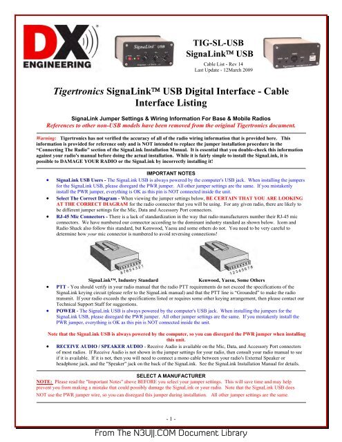
TIG-SL-<strong>USB</strong><br />
SignaLink <strong>USB</strong><br />
<strong>Cable</strong> List - Rev 14<br />
Last Update - 12March 2009<br />
<strong>Tigertronics</strong> SignaLink <strong>USB</strong> <strong>Digital</strong> <strong>Interface</strong> - <strong>Cable</strong><br />
<strong>Interface</strong> Listing<br />
SignaLink Jumper Settings & Wiring Information For Base & Mobile Radios<br />
References to other non-<strong>USB</strong> models have been removed from the original <strong>Tigertronics</strong> document.<br />
Warning: <strong>Tigertronics</strong> has not verified the accuracy of all of the radio wiring information that is provided here. This<br />
information is provided for reference only and is NOT intended to replace the jumper installation procedure in the<br />
“Connecting The Radio” section of the SignaLink Installation Manual. It is essential that you double-check this information<br />
against your radio's manual before doing the actual installation. While it is fairly simple to install the SignaLink, it is<br />
possible to DAMAGE YOUR RADIO or the SignaLink by incorrectly installing it!<br />
IMPORTANT NOTES<br />
• SignaLink <strong>USB</strong> Users - The SignaLink <strong>USB</strong> is always powered by the computer's <strong>USB</strong> jack. When installing the jumpers<br />
for the SignaLink <strong>USB</strong>, please disregard the PWR jumper. All other jumper settings are the same. If you mistakenly<br />
install the PWR jumper, everything is OK as this pin is NOT connected inside the unit.<br />
• Select The Correct Diagram - When viewing the jumper settings below, BE CERTAIN THAT YOU ARE LOOKING<br />
AT THE CORRECT DIAGRAM for the radio connector that you will be using. For any given radio, there are likely to<br />
be different jumper settings for the Mic, Data and Accessory Port connectors.<br />
• RJ-45 Mic Connectors - There is a lack of standardization in the way that radio manufacturers number their RJ-45 mic<br />
connectors. We have numbered our connector according to the dominant industry standard as shown below. Icom and<br />
Radio Shack also follow this standard, but Kenwood, Yaesu and some others do not. You need to be very careful to<br />
determine how your mic connector is numbered to avoid reversing connections!<br />
SignaLink, Industry Standard<br />
Kenwood, Yaesu, Some Others<br />
• PTT - You should verify in your radio manual that the radio PTT requirements do not exceed the specifications of the<br />
SignaLink keying circuit (please refer to the SignaLink manual) and that the PTT line is “Grounded” to make the radio<br />
transmit. If your radio exceeds the specifications listed or requires some other keying arrangement, then please contact our<br />
Technical Support Staff for suggestions.<br />
• POWER - The SignaLink <strong>USB</strong> is always powered by the computer's <strong>USB</strong> jack. When installing the jumpers for the<br />
SignaLink <strong>USB</strong>, please disregard the PWR jumper. All other jumper settings are the same. If you mistakenly install the<br />
PWR jumper, everything is OK as this pin is NOT connected inside the unit.<br />
Note that the SignaLink <strong>USB</strong> is always powered by the computer, so you can disregard the PWR jumper when installing<br />
this unit.<br />
• RECEIVE AUDIO / SPEAKER AUDIO - Receive Audio is available on the Mic, Data, and Accessory Port connectors<br />
of most radios. If Receive Audio is not shown in the jumper settings for your radio, then consult your radio manual to see<br />
if it is available. If it is not, then you will need to connect a mono cable between your radio's External Speaker or<br />
headphone jack, and the "Speaker" jack on the back of the SignaLink. See the SignaLink Installation Manual for details.<br />
SELECT A MANUFACTURER<br />
NOTE: Please read the "Important Notes" above BEFORE you select your jumper settings. This will save time and may help<br />
prevent you from making a mistake that could possibly damage the SignaLink or your radio. Note that the SignaLink <strong>USB</strong> does<br />
NOT use the PWR jumper wire, so you can disregard this jumper during installation. All other jumper settings are the same.<br />
- 1 -<br />
From The <strong>N3UJJ</strong>.COM Document Library
ADI<br />
8-Pin Round Mic Connector use TIG-SL-CAB8R<br />
JP-1<br />
Pin-out<br />
Pin 1 - Mic Input<br />
Pin 2 - PTT<br />
Pin 3 - N/C<br />
Pin 4 - N/C<br />
Pin 5 - N/C<br />
Pin 6 - Speaker**<br />
Pin 7 - N/C<br />
Pin 8 - GND<br />
Radio Models<br />
AR-146/147/446<br />
Notes<br />
**Speaker audio is available on some<br />
models. Check your radio manual for<br />
availability of these signals and add the<br />
appropriate jumpers.<br />
ALINCO<br />
8-Pin Round Mic Connector use TIG-SL-CAB8R<br />
JP-1<br />
Pin-out<br />
Pin 1 – Mic Input<br />
Pin 2 – PTT<br />
Pin 3 – N/C<br />
Pin 4 – N/C<br />
Pin 5 – N/C<br />
Pin 6 – N/C**<br />
Pin 7 – GND<br />
Pin 8 – GND<br />
Radio Models<br />
ALD-24T<br />
ALR-22T/22HT/72T<br />
DR-110T/112T<br />
DR-130T/135E/135T<br />
DR-150/235T<br />
DR-430T/435E/435T<br />
DR-510T/570T<br />
DR-590T/592T/599T<br />
DR-600T/610E/610T<br />
DR-620E/620T<br />
DX-70T/70TH/70EH<br />
DX-77<br />
Notes<br />
**Speaker audio is available on some<br />
models. Check your radio manual for<br />
availability of these signals and add the<br />
appropriate jumpers.<br />
RJ-45 Mic Connector TIG-SL-CABRJ4<br />
JP-1<br />
Pin-out<br />
Pin 1 – N/C<br />
Pin 2 – N/C<br />
Pin 3 – N/C<br />
Pin 4 – PTT<br />
Pin 5 – Mic GND<br />
Pin 6 – Mic Input<br />
Pin 7 – GND<br />
Pin 8 – N/C<br />
Radio Models<br />
DR-605E/605T<br />
Notes<br />
Speaker audio is available on some<br />
models. Check your radio manual for<br />
availability of these signals and add the<br />
appropriate jumpers.<br />
AZDEN<br />
8-Pin Round Mic Connector TIG-SL-CAB8R<br />
JP-1<br />
Pin-out<br />
Pin 1 – Mic Input<br />
Pin 2 – GND<br />
Pin 3 – N/C<br />
Pin 4 – N/C<br />
Pin 5 – N/C<br />
Pin 6 – N/C<br />
Pin 7 – PTT<br />
Pin 8 – N/C<br />
Radio Models<br />
PCS 5000/6000<br />
PCS 7000<br />
Notes<br />
Speaker audio is available on some<br />
models. Check your radio manual for<br />
availability of these signals and add the<br />
appropriate jumpers.<br />
- 2 -<br />
From The <strong>N3UJJ</strong>.COM Document Library
DRAKE<br />
4-Pin Round Mic Connector TIG-SL-CAB4R<br />
JP-1<br />
Pin-out<br />
Pin 1 – Mic Input<br />
Pin 2 – PTT<br />
Pin 3 – N/C<br />
Pin 4 – GND<br />
Radio Models<br />
TR-7/22/33<br />
UV-3<br />
Notes<br />
Elecraft<br />
8-Pin Round Mic Connector TIG-SL-CAB8R<br />
JP-1<br />
Pin-out<br />
Pin 1 - Mic<br />
Pin 2 - PTT<br />
Pin 3 - NC<br />
Pin 4 - NC<br />
Pin 5 - NC<br />
Pin 6 - +5VDC<br />
Pin 7 - GND<br />
Pin 8 - GND<br />
Radio Models<br />
K2<br />
K3<br />
Notes<br />
The Mic jack on the K2 can be wired a<br />
number of different ways, so before<br />
installing the jumper wires, you MUST<br />
verify that the pin-out of your K2 matches<br />
that shown here.<br />
ICOM<br />
4-Pin Round Mic Connector TIG-SL-CAB4R<br />
JP-1<br />
Pin-out<br />
Pin 1 – Mic Input<br />
Pin 2 – PTT<br />
Pin 3 – N/C<br />
Pin 4 – GND<br />
Radio Models<br />
IC-22/202/215<br />
IC-245/280/402/502<br />
IC-551<br />
IC-701<br />
Notes<br />
- 3 -<br />
From The <strong>N3UJJ</strong>.COM Document Library
8-Pin Round MIC Connector TIG-SL-CAB8R<br />
IMPORTANT: This diagram is for the MIC JACK only. If the SignaLink is attached to your radio's 8-pin Accessory Port,<br />
then please see the diagram below under "8-pin DIN Accessory Port Connector".<br />
JP-1<br />
Pin-out<br />
Pin 1 – Mic Input<br />
Pin 2 – N/C**<br />
Pin 3 – N/C<br />
Pin 4 – N/C<br />
Pin 5 – PTT<br />
Pin 6 – GND<br />
Pin 7 – GND<br />
Pin 8 – Speaker**<br />
Radio Models<br />
IC-1201/1271/1275<br />
IC-22U/25/27/28<br />
IC-228/229/251AE<br />
IC-255/260/271/290<br />
IC-2400/2500<br />
IC-37A/38A/375<br />
IC-3200/3210/3220<br />
IC-45/47/48<br />
IC-471/475/490<br />
IC-505/551/560/575<br />
IC-707/718/720/725/726<br />
IC-728/729/730/735<br />
IC-736/737/738/740/745<br />
IC-746/746PRO<br />
IC-756/756PRO<br />
IC-756PROII/PROIII<br />
IC-7400/7700/7800<br />
IC-751/761/765/775/781<br />
IC-820H/901/910<br />
Notes<br />
**Speaker audio (usually Pin #8)<br />
is available on some models.<br />
Check your radio manual for<br />
availability of these signals and<br />
add the appropriate jumpers.<br />
** Check Other Listings for these radios - you may be able to use the DIN, PACKET , ACCESSORY, or DATA jack **<br />
RJ-45 Mic Connector TIG-SL-CABRJ4<br />
JP-1<br />
Pin-out<br />
Pin 1 – +8V**<br />
Pin 2 – N/C<br />
Pin 3 – Speaker**<br />
Pin 4 – PTT<br />
Pin 5 – GND (mic)<br />
Pin 6 – Mic Input<br />
Pin 7 – GND<br />
Pin 8 – N/C<br />
Radio Models<br />
IC-207H**/208H**<br />
IC-281A/281E/281H<br />
IC-703/706/706MKII<br />
IC-2000<br />
IC-2100H**/2200H**<br />
IC-2700**/2720H**<br />
IC-2800**<br />
IC-7000**<br />
IC-V8000**<br />
ID-800H**<br />
Notes<br />
**Speaker audio is available on some<br />
models. Check your radio manual for<br />
availability of these signals and add the<br />
appropriate jumpers.<br />
**Speaker Audio is NOT available on the<br />
Mic jack of this radio.<br />
** Check Other Listings for these radios - you may be able to use the DIN, PACKET , ACCESSORY, or DATA jack **<br />
6-pin Mini DIN Data Port Connector TIG-SL-CAB6PM<br />
JP-1<br />
Pin-out<br />
Pin 1 – Data In<br />
Pin 2 – Ground<br />
Pin 3 – PTT<br />
Pin 4 – 9600 Out<br />
Pin 5 – 1200 Out<br />
Pin 6 – Squelch<br />
Radio Models<br />
IC-207H/208H<br />
IC-2720H<br />
IC-2800**<br />
IC-2820<br />
IC-703/706MKIIG<br />
IC-746PRO<br />
IC-7000 / 7400<br />
IC-910H<br />
Notes<br />
For special signals requiring un-filtered<br />
"discriminator" audio, you will need to<br />
move the "SPKR" jumper to pin #4 (9600<br />
baud output). Note that some newer radios<br />
do NOT provide this output, so this may not<br />
apply to your radio.<br />
**Mic audio is NOT muted on this radio.<br />
- 4 -<br />
From The <strong>N3UJJ</strong>.COM Document Library
8-pin DIN Accessory Port Connector TIG-SL-CAB8PD<br />
IMPORTANT: This diagram is for the ACCY PORT only. If the SignaLink is attached to your radio's 8-pin Round Mic<br />
Jack, then please see the diagram above under "8-Pin Round MIC Connector".<br />
JP-1<br />
Pin-out<br />
Pin 1 - RTTY or N/C<br />
Pin 2 - Ground<br />
Pin 3 - Send<br />
Pin 4 - Mod In<br />
Pin 5 - AF Out<br />
Pin 6 - Squelch<br />
Pin 7 - +13.8V<br />
Pin 8 - ALC<br />
Radio Models<br />
IC-275A<br />
IC-707<br />
IC-725/728/729<br />
IC-735/736/737<br />
IC-7400<br />
IC-746**<br />
IC-746PRO**<br />
IC-756 / 756PRO<br />
IC-756PROII / III<br />
IC-761/765<br />
IC-775/775DSP<br />
IC-781<br />
IC-7700/7800<br />
IC-820H/821H<br />
IC-910H<br />
IC-M700PRO<br />
IC-M710<br />
IC-M802<br />
Notes<br />
IC-756PRO users should use digital mode<br />
"D-<strong>USB</strong>" or "D-LSB".<br />
**Some customers have reported that the<br />
IC-746 (early model only) does NOT mute<br />
the Mic when keyed from the Accy Port. If<br />
this is the case with your radio, then you<br />
will need to turn the radio's Mic Gain down<br />
and/or unplug the microphone.<br />
**Due to the design of the IC-746PRO, this<br />
jack does NOT support VHF operation. If<br />
you want to operate both HF and VHF, then<br />
you'll need to use the 6-pin mini-DIN Data<br />
Port instead.<br />
**IC-746PRO users should use "<strong>USB</strong>/LSB<br />
Data" mode (not regular <strong>USB</strong>/LSB).<br />
IC-820H users need to set the Modulation<br />
Input Sensitivity switch to "Low", and the<br />
Baud Rate Selection switch to "AMOD".<br />
13-pin DIN Accessory Port Connector TIG-SL-CAB13I<br />
JP-1<br />
Pin-out<br />
<strong>Tigertronics</strong> manufactures a<br />
special cable for ICOM 13-<br />
pin Accessory Ports. If you<br />
would like to build your<br />
own 13-pin cable (not<br />
recommended!), please<br />
contact our Technical<br />
Support Staff for pin-out<br />
and wiring information.<br />
Radio Models<br />
IC-703<br />
IC-706/706MKII<br />
IC-706MKIIG<br />
IC-718<br />
IC-7000**<br />
Notes<br />
For VHF operation on the IC-706 and IC-<br />
706MKII you will need to move the PTT<br />
jumper to Pin #4.<br />
For VHF/UHF operation on the IC-<br />
706MKIIG and IC-7000, you should turn<br />
the following menu item to OFF:<br />
Item #30 for IC-706MKIIG<br />
Item #20 for IC-7000<br />
This will force the radio to use the same<br />
PTT pin for all bands so will not need to<br />
change the SignaLink's jumper settings.<br />
**This radio does NOT mute the Mic jack<br />
when using the Accy Port, so you will need<br />
to turn the Mic Gain down, or use the 6-pin<br />
Mini Din Data Port instead.<br />
- 5 -<br />
From The <strong>N3UJJ</strong>.COM Document Library
24-pin DIN Accessory Port Connector - <strong>Tigertronics</strong> does not manufacture a cable for the ICOM 24-pin Accessory Port connector,<br />
but you can easily build one using our un-terminated radio cable (p/n SLCABNC). To build your cable, simply wire it straightthrough<br />
for pin numbers 1-8 (Pin #1 to Pin #1, Pin #2 to Pin #2, etc.). Note that your cable MUST wired straight-through or the<br />
jumper settings shown below will NOT work, and you might DAMAGE YOUR RADIO OR THE SIGNALINK!<br />
JP-1<br />
Pin-out<br />
Pin 1 - NC<br />
Pin 2 - +13.8V<br />
Pin 3 - PTT<br />
Pin 4 - AF Out<br />
Pin 5 - Mic Input<br />
Pin 6 - NC<br />
Pin 7 - NC<br />
Pin 8 - GND<br />
Pins 9-24 NC<br />
Radio Models<br />
IC-251AE<br />
IC-730/751<br />
Notes<br />
Pins marked as "NC" are not used by the<br />
SignaLink, but might be connected<br />
internally inside the radio.<br />
Japan Radio Company<br />
8-Pin Round Mic Connector TIG-SL-CAB8R<br />
JP-1<br />
Pin-out<br />
Pin 1 - N/C<br />
Pin 2 - N/C<br />
Pin 3 - N/C<br />
Pin 4 - +9V<br />
Pin 5 - GND<br />
Pin 6 - PTT<br />
Pin 7 - Mic GND<br />
Pin 8 - Mic Input<br />
Radio Models<br />
JST-145/245<br />
Notes<br />
KENWOOD<br />
4-Pin Round Mic Connector TIG-SL-CAB4R<br />
JP-1<br />
Pin-out<br />
Pin 1 – Mic Input<br />
Pin 2 – PTT<br />
Pin 3 – GND<br />
Pin 4 – Mic GND<br />
Radio Models<br />
TR-7200A<br />
TR-7400A<br />
TR-7500<br />
TS-120S/130S/180S<br />
TS-511S/520/530<br />
TS-600/700/820/830<br />
Notes.<br />
** Check Other Listings for these radios - you may be able to use the DIN, PACKET , ACCESSORY, or DATA jack **<br />
- 6 -<br />
From The <strong>N3UJJ</strong>.COM Document Library
8-Pin Round Mic Connector TIG-SL-CAB8R<br />
JP-1<br />
Pin-out<br />
Pin 1 – Mic Input<br />
Pin 2 – PTT<br />
Pin 3 – N/C<br />
Pin 4 – N/C<br />
Pin 5 – 8 VDC**<br />
Pin 6 – Speaker**<br />
Pin 7 – Mic GND<br />
Pin 8 – GND<br />
Radio Models<br />
TM-201/211/221/231<br />
TM-241/2530/2550<br />
TM-2570<br />
TM-321/331/3530/401<br />
TM-421/431/441/521<br />
TM-531/541/621/631<br />
TM-701/721/731<br />
TR-50/751/851<br />
TS-50/60/140/430/440<br />
TS-450/570/660/670<br />
TS-680/690/701/711<br />
TS-780/790/811/850<br />
TS-870/930/940/950<br />
TS-2000<br />
TW-4000/4100<br />
Notes<br />
**Speaker audio is available on some<br />
models. Check your radio manual for<br />
availability of these signals and add the<br />
appropriate jumpers.<br />
** Check Other Listings for these radios - you may be able to use the DIN, PACKET , ACCESSORY, or DATA jack **<br />
RJ-45 Mic Connector TIG-SL-CABRJ4<br />
JP-1<br />
Pin-out<br />
Pin 1 – NC<br />
Pin 2 – Speaker**<br />
Pin 3 – Mic<br />
Pin 4 – GND<br />
Pin 5 – PTT<br />
Pin 6 – GND<br />
Pin 7 – +8V**<br />
Pin 8 – NC<br />
Radio Models<br />
TM-251/255/261/271<br />
TM-451/455/461<br />
TM-641/642<br />
TM-732/733/741/742<br />
TM-941/942<br />
TM-D700A<br />
TM-G707<br />
TM-V7A/V71A<br />
TS-480HX/SAT<br />
Notes<br />
**Speaker audio is available on some<br />
models. Check your radio manual for<br />
availability of these features and add the<br />
appropriate jumpers.<br />
** Check Other Listings for these radios - you may be able to use the DIN, PACKET , ACCESSORY, or DATA jack **<br />
6-pin Mini DIN Data Port Connector TIG-SL-CAB6PM<br />
JP-1<br />
Pin-out<br />
Pin 1 – Data In<br />
Pin 2 – Ground<br />
Pin 3 – PTT<br />
Pin 4 – 9600 Out<br />
Pin 5 – 1200 Out<br />
Pin 6 – Squelch<br />
Radio Models<br />
TM-251<br />
TM-271**/271A**<br />
TM-451<br />
TM-D700/D700A<br />
TM-D710/710A/E<br />
TM-G707<br />
TM-V7/V7A/V71A<br />
TS-480HX/SAT<br />
Notes<br />
For special signals requiring un-filtered<br />
"discriminator" audio, you will need to move<br />
the "SPKR" jumper to pin #4 (9600 baud<br />
output). Note that some newer radios do<br />
NOT provide this output, so this may not<br />
apply to your radio.<br />
**Only European models of the TM-271 and<br />
TM-271A have the 6-pin mini-DIN Data<br />
Port. All other models will need to use the<br />
RJ-45 Mic cable.<br />
** Check Other Listings for these radios - you may be able to use the DIN, PACKET , ACCESSORY, or DATA jack **<br />
- 7 -<br />
From The <strong>N3UJJ</strong>.COM Document Library
13-pin DIN Accessory Port Connector TIG-SL-CAB13K<br />
Our 13-pin cable works with ALL Kenwood radio's that have a 13-pin Accessory Port, however there are two possible jumper<br />
settings. If your radio is not listed in Figure 1 or Figure 2, then you will need to try both jumper settings to determine which PTT<br />
configuration your radio requires. We suggest that you try the settings in Figure 1 first. Your radio will NOT be damaged if you<br />
install the PTT jumper using the wrong configuration - you just won’t be able to transmit! After you have installed the<br />
jumpers, be sure to set the sound card audio levels as outlined in the SignaLink manual. If you do not set the levels correctly, then the<br />
SignaLink may not transmit, and you might mistake the problem for incorrect jumper settings.<br />
Figure 1 Figure 2 Notes<br />
TS-2000 users should set Menu 50F to 1200<br />
Baud. Menu 50B can be used to increase the<br />
radio's power output if it is too low. We suggest<br />
that you change these menu items even if they<br />
already appear to be set correctly. Set 50B to<br />
zero, and then to five. Set 50F to 9600, and then<br />
to 1200. To increase the Receive Audio Level on<br />
the TS-2000, you can adjust menu 50C.<br />
This configuration is the most common<br />
and works with early Kenwood radios<br />
such as the TS-140, TS-450S, TS-870 and<br />
TS-950. Some newer radios such as the<br />
TS-570D and TS-2000/X also use these<br />
settings.<br />
This configuration is less common and is<br />
used by some newer radios (TS-690 for<br />
example) and some older radios such as the<br />
TS-440. These settings are identical to those<br />
in Figure 1, except for the PTT jumper,<br />
which has been replaced by a diode module<br />
(supplied with cable).<br />
TS-570 users should set Menu #33 to 1 or 2 (a<br />
setting of zero will result in no transmit power).<br />
Menu #34 should be set at 4-5 and can be<br />
increased to provide more Receive Audio if<br />
needed.<br />
MIDLAND<br />
4-Pin Round Mic Connector TIG-SL-CAB4R<br />
JP-1<br />
Pin-out<br />
Pin 1 – Mic Input<br />
Pin 2 – GND<br />
Pin 3 – N/C<br />
Pin 4 – PTT<br />
Radio Models<br />
13-510<br />
Notes<br />
RADIO SHACK<br />
RJ-45 Mic Connector TIG-SL-CABRJ4<br />
JP-1<br />
Pin-out<br />
Pin 1 – N/C<br />
Pin 2 – GND<br />
Pin 3 – N/C<br />
Pin 4 – N/C<br />
Pin 5 – Mic Input<br />
Pin 6 – PTT<br />
Pin 7 – N/C<br />
Pin 8 – N/C<br />
Radio Models<br />
HTX-212<br />
HTX-242<br />
Notes<br />
Speaker audio is available on some models.<br />
Check your radio manual for availability of<br />
these signals and add the appropriate jumpers.<br />
- 8 -<br />
From The <strong>N3UJJ</strong>.COM Document Library
SGC<br />
8-Pin Round Mic Connector TIG-SL-CAB8R<br />
JP-1<br />
Pin-out<br />
Pin 1 – Mic<br />
Pin 2 – PTT<br />
Pin 3 – NC<br />
Pin 4 – NC<br />
Pin 5 – NC<br />
Pin 6 – RX Audio<br />
Pin 7 – Mic GND<br />
Pin 8 – GNC<br />
Radio Models<br />
SGC-2020<br />
Notes<br />
TEN-TEC<br />
4-Pin Round Mic Connector TIG-SL-CAB4R<br />
JP-1<br />
Pin-out<br />
Pin 1 – Mic Input<br />
Pin 2 – GND<br />
Pin 3 – PTT<br />
Pin 4 – N/C<br />
Radio Models<br />
Pegasus<br />
Notes<br />
These jumper settings work with most Ten-<br />
Tec Mic jacks (not just the Pegasus).<br />
However you should verify that your radio has<br />
the same pin-out before installing them.<br />
** Check Other Listings for these radios - you may be able to use the DIN, PACKET , ACCESSORY, or DATA jack **<br />
5-Pin DIN Accessory Connector - TIG-SL-CAB5PD<br />
JP-1<br />
Pin-out<br />
Pin 1 - Mic Input<br />
Pin 2 - GND<br />
Pin 3 - PTT<br />
Pin 4 - AF Output<br />
Pin 5 - NC<br />
Radio Models<br />
Argonaut V<br />
Jupiter<br />
Omni VII<br />
Pegasus<br />
Notes<br />
The Ten-Tec Jupiter must be in "Line" to use<br />
the ACCY jack (set in radio menu).<br />
8-Pin DIN Accessory Connector - Orion & Orion II Only TIG-SL-CAB8PD<br />
JP-1<br />
Pin-out<br />
Pin 1 - Aux In<br />
Pin 2 - GND<br />
Pin 3 - PTT<br />
Pin 4 - Line Out**<br />
Pin 5 - NC<br />
Pin 6 - Line Out**<br />
Pin 7 - FSK<br />
Pin 8 - NC<br />
Radio Models<br />
Orion<br />
Orion II<br />
TEN-TEC Delta II<br />
Users: Our 8-pin DIN<br />
cable is NOT compatible<br />
with the TEN-TEC Delta<br />
II. You must connect the<br />
SignaLink to this radio's<br />
4-pin Mic jack.<br />
Notes<br />
**On the original Orion, the "Audio" menu<br />
determines what audio is available on pins 4<br />
and 6, so the SPKR jumper will need to be set<br />
accordingly.<br />
**On the Orion II, Pin #4 is ALWAYS the<br />
audio output.<br />
.<br />
- 9 -<br />
From The <strong>N3UJJ</strong>.COM Document Library
YAESU<br />
4-Pin Round Mic Connector TIG-SL-CAB4R<br />
JP-1<br />
Pin-out<br />
Pin 1 – GND<br />
Pin 2 – Mic Input<br />
Pin 3 – PTT<br />
Pin 4 – N/C<br />
Radio Models<br />
Notes<br />
8-Pin Round Mic Connector TIG-SL-CAB8R<br />
JP-1<br />
Pin-out<br />
Pin 1 – N/C<br />
Pin 2 – N/C<br />
Pin 3 – N/C<br />
Pin 4 – N/C<br />
Pin 5 – N/C<br />
Pin 6 – PTT<br />
Pin 7 – GND<br />
Pin 8 – Mic Input<br />
Radio Models<br />
FT-747/757<br />
FT-757GX/767GX<br />
FT-840<br />
FT-847**<br />
FT-890**<br />
FT-920**<br />
FT-950**<br />
FT-990**<br />
FT-1000**<br />
FT-1000D**<br />
FT-1000MP**<br />
FT-2200<br />
FT-5100<br />
Notes<br />
**On the FT-890, FT-990, and the FT-<br />
1000 and 1000D, you should also jumper<br />
Pin #2 and Pin #5 to Ground.<br />
**On the FT-847, FT-920, FT-950 and FT-<br />
1000MP, you should also jumper Pin #5 to<br />
Ground.<br />
Speaker audio is available on some<br />
models. Check your radio manual for<br />
availability of these signals and add the<br />
appropriate jumpers.<br />
** Check Other Listings for these radios - you may be able to use the DIN, PACKET , ACCESSORY, or DATA jack **<br />
RJ-11 Mic Connector TIG-SL-CABRJ1<br />
JP-1<br />
Pin-out<br />
Pin 1 – N/C<br />
Pin 2 – N/C<br />
Pin 3 – +9V<br />
Pin 4 – GND<br />
Pin 5 – Mic Input<br />
Pin 6 – SW1<br />
Pin 7 – N/C<br />
Pin 8 – N/C<br />
Radio Models<br />
FT-100**<br />
FT-1500M<br />
FT-1802<br />
FT-2800M<br />
FT-7800R<br />
Notes<br />
**With the FT-100, the PTT jumper MUST<br />
be replaced with a standard 1/4 watt 27k<br />
resistor.<br />
Other Yaesu models with an RJ-11 Mic jack<br />
might also use these same settings (check<br />
your radio manual).<br />
** Check Other Listings for these radios - you may be able to use the DIN, PACKET , ACCESSORY, or DATA jack **<br />
- 10 -<br />
From The <strong>N3UJJ</strong>.COM Document Library
RJ-45 Mic Connector TIG-SL-CABRJ4<br />
JP-1<br />
Pin-out<br />
Pin 1 – N/C<br />
Pin 2 – Speaker<br />
Pin 3 – PTT<br />
Pin 4 – Mic Input<br />
Pin 5 – GND<br />
Pin 6 – N/C<br />
Pin 7 – N/C<br />
Pin 8 – N/C<br />
Radio Models<br />
FT-2400<br />
FT-2500<br />
Notes<br />
Speaker audio is available on some models.<br />
Check your radio manual for availability of<br />
these signals and add the appropriate<br />
jumpers.<br />
Pin-out<br />
Pin 1 – N/C<br />
Pin 2 – N/C<br />
Pin 3 – N/C<br />
Pin 4 – Mic GND<br />
Pin 5 – Mic<br />
Pin 6 – PTT<br />
Pin 7 – GND<br />
Pin 8 – N/C<br />
Radio Models<br />
FT-450<br />
FT-817<br />
FT-897<br />
FT-900<br />
Notes<br />
Receive Audio is not available on this<br />
connector.<br />
** Check Other Listings for these radios - you may be able to use the DIN, PACKET , ACCESSORY, or DATA jack **<br />
5-Pin Din Packet Connector TIG-SL-CAB5PD<br />
JP-1<br />
Pin-out<br />
Pin 1 – Data In<br />
Pin 2 – GND<br />
Pin 3 – PTT<br />
Pin 4 – Data Out<br />
Pin 5 – NC<br />
Radio Models<br />
FT-920**<br />
FT-1000D/MP**<br />
FT-1000MPMKV**<br />
FT-1000MPMKV-<br />
Field**<br />
FT-2000<br />
FTDX-9000/D/MP<br />
Notes<br />
**On the FT-920, the AFSK/FSK switch MUST be set to<br />
AFSK, and you must be in "Data" mode (push the front<br />
panel "Data" button). The Mic Gain control appears to<br />
affect the operation of the Packet jack, so we suggest<br />
setting this to 50% and then adjusting as needed..<br />
**The FT-1000MPMKV and FT-1000MKV Field MUST<br />
be in "Packet" mode (NOT usb!) for digital operation. For<br />
PSK31 or other "<strong>USB</strong>" digital modes, you'll need to set<br />
your radio's "User Mode" (selection 8-6) to "PS31U". This<br />
will configure the radio to look at the Packet jack and use<br />
the correct side band for PSK31. For more detailed<br />
information on this (including settings for other modes),<br />
see "<strong>Digital</strong> Modem Operation" in your radio manual.<br />
**This jack supports only FM and LSB, which is not<br />
compatible with the majority of digital modes.<br />
6-pin Mini DIN Data Port Connector TIG-SL-CAB6PM<br />
JP-1<br />
Pin-out<br />
Pin 1 – Data In<br />
Pin 2 – Ground<br />
Pin 3 – PTT<br />
Pin 4 – 9600 Out<br />
Pin 5 – 1200 Out<br />
Pin 6 – Squelch<br />
Radio Models<br />
FT-100/100D<br />
FT-817/817ND<br />
FT-450<br />
FT-847**<br />
FT-857/897***<br />
FT-950<br />
FT-1500M<br />
FT-7100/7800R<br />
FT-8100/8800R<br />
FT-8900R<br />
Notes<br />
For special signals requiring un-filtered<br />
"discriminator" audio, you will need to move<br />
the "SPKR" jumper to pin #4 (9600 baud<br />
output). Note that some newer radios do<br />
NOT provide this output, so this may not<br />
apply to your radio.<br />
**On the FT-847 the Data Port supports VHF<br />
& UHF Packet only.<br />
*** On the FT-897 Data level may be too<br />
low to work with MACs and require internal<br />
mod to SL unit by factory.<br />
- 11 -<br />
From The <strong>N3UJJ</strong>.COM Document Library
FT-847 ONLY - 3.5mm Stereo "Data I/O" jack TIG-SL-CABNC<br />
For the FT-847, we recommend that you attach the SignaLink to the "Data I/O" jack. This jack works for all modes and will let you<br />
keep your microphone plugged into the radio. We do not stock a cable for this jack however, so you will need to build your own<br />
using one of our un-terminated radio cables. The picture below shows how to wire this cable and install the jumper wires.<br />
© DX Engineering 2009<br />
P.O. Box 1491 · Akron, OH 44309-1491<br />
Phone: (800) 777-0703 · Tech Support and International: (330) 572-3200<br />
Fax: (330) 572-3279 · E-mail: DXEngineering@DXEngineering.com<br />
© 1996-2009 <strong>Tigertronics</strong>. All Rights Reserved , BayPac, SignaLink, and TigerTrak are trademarks of <strong>Tigertronics</strong><br />
All other trademarks are the property of their respective owners<br />
Specifications subject to change without notice<br />
- 12 -<br />
From The <strong>N3UJJ</strong>.COM Document Library