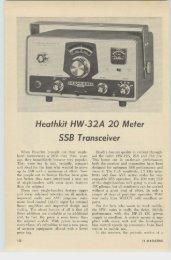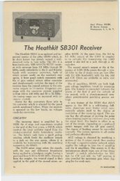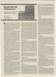
The Heathkit SB-401 Transmitter - Nostalgic Kits Central
The Heathkit SB-401 Transmitter - Nostalgic Kits Central
The Heathkit SB-401 Transmitter - Nostalgic Kits Central

Create successful ePaper yourself
Turn your PDF publications into a flip-book with our unique Google optimized e-Paper software.
sideband carrier generator, at 3393.6 kHz.<br />
~ Another triode section is for the upper sideband<br />
carrier at 3396.4 kHz, and in the<br />
CW mode, uses another crystal at 3395.4<br />
kHz. Only that triode selected by the mode<br />
switch receives plate voltage. <strong>The</strong> third triode<br />
is a cathode follower in all modes.<br />
Audio from the speech-amplifier cathode<br />
follower and carrier from the sideband genera<br />
tor are fed to a diode ring balanced<br />
modulator whose output is the sum and<br />
difference of the audio and carrier frequencies.<br />
\Vhen operating on C\ V, a small<br />
de voltage upsets the balance of the modulator,<br />
producing output on the C\V carrier<br />
frequency.<br />
<strong>The</strong> signal is then coupled through a transfanner<br />
to the grid of a 6AV6. which isolates<br />
the balanced modulator from the crystal<br />
filter and provides for the proper impcdance<br />
matching. This stage is also partially<br />
controlled by ALC (automatic level<br />
control) voltage which will be mentioned<br />
later. From the isolation amplifier, the signal<br />
next goes to a 2.1 kHz crystal lattice filter,<br />
emerging to be coupled to the grid of the<br />
6E\V6 mixer.<br />
<strong>The</strong> <strong>SB</strong><strong>401</strong>'s VFO operates over a range<br />
of 5 to 5.5 mHz, its output passing to the<br />
cathode of the 6E\V6 mixer, which produces<br />
the sum and difference of the VFO<br />
and previously generated frequencies. <strong>The</strong><br />
sum frequency is then coupled through a<br />
bandpass coupler (8.395 to 8.895 MHz) to<br />
the grid of the heterodyne mixer. another<br />
6EW6.<br />
<strong>The</strong> triode portion of a 6A\V8 is a<br />
heterodyne oscillator whose plate voltage<br />
is regulated, and whose frequency is deten<br />
nined by one of the eight switch-selected<br />
crystals. Its output is also coupled to the<br />
grid of the 6EW6 heterodyne mixer. In<br />
passing, note that the sale function of the<br />
pentode section of the same 6A\V8 is to<br />
amplify the heterodyne oscillator input from<br />
the companion receiver, the 513301, when<br />
operating transceive. Only when the mode<br />
switch is in the "transceive" position is<br />
plate voltage applied to this part of the<br />
tube. In the "independent transmit" posiion,<br />
voltage is applied instead to the plate<br />
of the 6A\V8 heterodyne oscillator.<br />
<strong>The</strong> signals from th e bandpass coupler<br />
and heterodyne oscillator are mixed in the<br />
6EW6 heterodyne mixer. Only the difference<br />
frequencies reach the grid of the<br />
6CL6 driver tube. A trap in the driver grid<br />
suppresses a spurious signal at 8.6 MHz<br />
which might otherwise appear in the output<br />
on the 7 MHz band.<br />
Driver output is applied to the grids of<br />
a pair of 6146's in parallel, operating in<br />
Class ABI. An internal pot sets bias at -50<br />
volts to hold the no-signal plate current<br />
at 50 rnA.<br />
Peak driving voltage for the finals is<br />
variable with the C\ V level control, which<br />
is in tandem with the microphone gain on<br />
the front panel. In S<strong>SB</strong> operation, the limittug<br />
action of the ALe circuitry also affects<br />
the driving voltage.<br />
A conventional pi network couples final<br />
output to the antenna. Impedances of approximately<br />
40 to 150 ohms can be matched.<br />
A built-in relay automatically transfers the<br />
antenna from the transmitter to the receiver.<br />
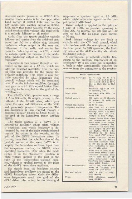
Frequency CoveraKe:<br />
Emission :<br />
Input power:<br />
Out put power :<br />
Output impedance:<br />
F req uency sta bility:<br />
Sideband generation:<br />
Dial accuracy:<br />
Features :<br />
P ower requirements :<br />
Size and weight :<br />
P rice :<br />
8B-0I01 Specifications<br />
3.5 to 01.0; 7.0 to 7.5:<br />
14.0 to 101.5; 21.0 to 21.5;<br />
28.0 to 28.5; 28.5 to 29.0 :<br />
29.0 to 29.5 ; 29.5 to 30.0<br />
MHz.<br />
Selectable upper or lower<br />
sideband, CW o<br />
180 watta P EP 8<strong>SB</strong>, 170<br />
watta C W o<br />
100 watts on 80 throua-h<br />
15 meters ; 80 wa tts on<br />
on 10 meters.<br />
50 t o 75 ohms.<br />
Less than 100 H z d rift<br />
p er hour after 20 m inute<br />
wa rmup period. Less t han<br />
100 H z drift for 10%<br />
changes in line voltage.<br />
Crystal lattice filter . Car <br />
r ier suppression 55 dB<br />
down from rated output.<br />
Unwanted sideband suppression<br />
55 d B down f rom<br />
rated output at 1000 H :r.<br />
and h igher. Third or der<br />
distor tion 30 d B down<br />
f rom rated PEP ou tput.<br />
Visual accuracy w it h in<br />
200 H z on all bands :<br />
Electrical accur acy wit h <br />
in 01 00 H z on a ll bands<br />
a fter calibration to nearest<br />
100 kHz point.<br />
Noise level at Ieeet (0 dB<br />
below rated carrier ; audIo<br />
frequency response f rom<br />
350 to 2(50 H z ; 10 dB<br />
audio eompreeefon ; h igh<br />
impedance microphone a n d<br />
p hone-patch inputs.<br />
105-125 vee. 60/60 Hz. 80<br />
watts in stan dby; 260<br />
watts CW (key down).<br />
14 % " x 6%" x 13% " .<br />
26'h pounds.<br />
$285. (Op tion a l crystal<br />
pack $29.95).<br />
JULY 1967<br />
99